EP0217140A1 - Testing device, in particular for bottle-like containers, and method for testing the same - Google Patents
Testing device, in particular for bottle-like containers, and method for testing the same Download PDFInfo
- Publication number
- EP0217140A1 EP0217140A1 EP86111886A EP86111886A EP0217140A1 EP 0217140 A1 EP0217140 A1 EP 0217140A1 EP 86111886 A EP86111886 A EP 86111886A EP 86111886 A EP86111886 A EP 86111886A EP 0217140 A1 EP0217140 A1 EP 0217140A1
- Authority
- EP
- European Patent Office
- Prior art keywords
- bottle
- test
- piston
- container
- containers
- Prior art date
- Legal status (The legal status is an assumption and is not a legal conclusion. Google has not performed a legal analysis and makes no representation as to the accuracy of the status listed.)
- Granted
Links
Images

Classifications
-
- G—PHYSICS
- G01—MEASURING; TESTING
- G01M—TESTING STATIC OR DYNAMIC BALANCE OF MACHINES OR STRUCTURES; TESTING OF STRUCTURES OR APPARATUS, NOT OTHERWISE PROVIDED FOR
- G01M3/00—Investigating fluid-tightness of structures
- G01M3/02—Investigating fluid-tightness of structures by using fluid or vacuum
- G01M3/26—Investigating fluid-tightness of structures by using fluid or vacuum by measuring rate of loss or gain of fluid, e.g. by pressure-responsive devices, by flow detectors
- G01M3/32—Investigating fluid-tightness of structures by using fluid or vacuum by measuring rate of loss or gain of fluid, e.g. by pressure-responsive devices, by flow detectors for containers, e.g. radiators
- G01M3/3218—Investigating fluid-tightness of structures by using fluid or vacuum by measuring rate of loss or gain of fluid, e.g. by pressure-responsive devices, by flow detectors for containers, e.g. radiators for flexible or elastic containers
-
- B—PERFORMING OPERATIONS; TRANSPORTING
- B07—SEPARATING SOLIDS FROM SOLIDS; SORTING
- B07C—POSTAL SORTING; SORTING INDIVIDUAL ARTICLES, OR BULK MATERIAL FIT TO BE SORTED PIECE-MEAL, e.g. BY PICKING
- B07C5/00—Sorting according to a characteristic or feature of the articles or material being sorted, e.g. by control effected by devices which detect or measure such characteristic or feature; Sorting by manually actuated devices, e.g. switches
- B07C5/34—Sorting according to other particular properties
- B07C5/3404—Sorting according to other particular properties according to properties of containers or receptacles, e.g. rigidity, leaks, fill-level
- B07C5/3408—Sorting according to other particular properties according to properties of containers or receptacles, e.g. rigidity, leaks, fill-level for bottles, jars or other glassware
-
- G—PHYSICS
- G01—MEASURING; TESTING
- G01M—TESTING STATIC OR DYNAMIC BALANCE OF MACHINES OR STRUCTURES; TESTING OF STRUCTURES OR APPARATUS, NOT OTHERWISE PROVIDED FOR
- G01M3/00—Investigating fluid-tightness of structures
- G01M3/02—Investigating fluid-tightness of structures by using fluid or vacuum
- G01M3/36—Investigating fluid-tightness of structures by using fluid or vacuum by detecting change in dimensions of the structure being tested
- G01M3/366—Investigating fluid-tightness of structures by using fluid or vacuum by detecting change in dimensions of the structure being tested by isolating only a part of the structure being tested
Definitions
- the present invention relates to a test device, in particular for bottle-shaped containers, which is designed as a piston / cylinder unit, and a method for testing bottle-shaped containers, which consist essentially of plastic.
- the present invention aims to simplify the existing conditions in the sense that, in particular, containers to be filled with liquid material, which preferably consist mainly of plastic, can be checked before they are filled with the Be well filled to the committee, for example in terms of dimensioning, crush resistance, tightness and. To locate quickly and clearly before the filling process.
- liquid material which preferably consist mainly of plastic
- the present invention aims to improve such tests in every respect, i.e. in terms of space, time, machine requirements to make it easier.
- the present test device which takes this into account, is characterized by the fact that it has several pistons in order to test several properties of the container while the container and cylinder are in the same position.
- a corresponding method is characterized in that the container and the test device are brought into the test position and then with the both tested several properties of the container in the test position.
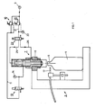
- a test system for testing plastic bottle-shaped containers is shown.
- a test object in the form of a bottle 4 can be seen in a test yoke 3, which can be arranged on a rotating or linearly moving feed line. It is a simple bottle with a bottle neck 5.
- a test device 7 is fastened in the upper yoke arm 6 of the test yoke 3. This device is designed as a piston / cylinder unit. This test device 7 is actuated by means of compressed air, a compressed air connection 9 with a pressure regulator 10 for regulating the air pressure required for determining the compressive strength of the bottle 4 being provided in the diagram.
- the system also includes a limit switch 17, which comes into operation when the bottle 4, on the neck 5 of which an axial pressure is exerted, does not have the required crush resistance and therefore the corresponding part of the test device 7 drops and thus actuates this limit switch 17.
- the limit switch 17 addressed in this way ensures that the corresponding bottle 4 is routed away as waste in the further course of the movement.
- a supply line 21 leads to a manometer 22 and to a 4/2-way valve 23.
- the one connection of this valve 23 is used to attach a supply line 25 for closing the bottle for its leak test using compressed air, while the second supply line 26 for return delivers the compressed air to the test device in its starting position.
- the test device 7 shown on an enlarged scale in FIG. 2 comprises an upper cylinder jacket and a lower 31.
- the upper cylinder jacket 30 is closed off by means of a cylinder cover 32.
- the two cylinder jackets 30 and 31 are screwed together via a connecting nipple 34.
- the lower cylinder jacket 31 is closed off by means of a cylinder end nipple 35.
- the end of this nipple 35 is threaded so that the device 7 can be fastened in the upper yoke arm 6 with the aid of a fastening ring 37 and a locking ring 38.
- the cylinder cover 32 is provided with a central compressed air connection bore 40. It leads into the interior of the cylinder jacket 30, in which an upper piston 41 is slidably arranged.
- the piston 41 is provided with an inner piston rod 42 with a free end surface 43.
- the piston 41 is sealed with respect to the cylinder jacket 30 by means of a lip sealing ring 44 and an O-ring 45.
- the piston rod 42 runs in an upper guide bush 47 which is inserted into the connecting nipple 34 and is provided with an O-ring seal 48.
- a compressed air bore 50 arranged laterally in the connecting nipple 34 is provided with a connecting nipple 51, through which compressed air can be supplied from the supply line 11.
- the connecting nipple 34 also has a vent hole 52 which opens into the cylinder chamber of the upper cylinder jacket 30.
- a lower piston 53 with a piston rod 54 is provided below the connecting nipple 34, which piston 53 is equipped with two lip sealing rings 55 and 56.
- the cylinder end nipple 35 has a lateral compressed air bore 58 with a nipple 59, which is sealed by means of an O-ring 60.
- the piston rod 54 is guided in a lower guide bush 62 with an O-ring seal 63 in the cylinder end nipple 35.
- the lower end of the piston rod 54 is designed as a threaded pin, which is used to hold a connection head 65, in the threaded bore 66 of which the threaded pin is screwed. Laterally in the head 65 two bores, a compressed air bore 67 and a connection bore for a pressure gauge 68 are radial. The two holes are connected to each other by a longitudinal hole. This longitudinal bore in turn opens into a lower threaded bore of the connection head 65.
- An inner sealing surface 75 is provided, for example when carrying out the leak test, for resting on the end edge of the bottle neck.
- the valve 23 is set such that the compressed air reaches the free end face of the upper piston 41 through the supply line 25 and the compressed air connection bore 40 and moves it downward.
- the free end of the piston rod 72 abuts with the surface 43 on the free surface of the lower piston 53, so that it pushes it down together with its piston rod 54 and the parts attached to it.
- the caliber measuring head 71 gets into the bottle neck 5 and checks its passage.
- the end cap 70 with its sealing surface 75 then reaches the upper edge of the bottle neck 5. During this movement, the upper piston 41 has reached its lower stop position.
- the supply line 26 is pressurized with compressed air (circuit according to FIG. 1), which pushes the piston 53 back and forth, the piston rod 42 with the piston 41 into the upper stop positions according to FIG. 2.
- the corresponding cylinder chamber is vented through the bore 50 by switching the valve 13 to "exhaust", as can be seen in FIG. 1. Accordingly, air is passed through line 25 through valve 23, as can be seen in FIG Atmosphere expelled. In order to prevent the formation of negative pressure in the upper cylinder chamber, air flows from the atmosphere through the ventilation hole 52 into the cylinder interior.
- Density testing and compression testing can be carried out in any way one after the other or together.
- the stroke of the upper piston 41 is therefore smaller, for example by 20 mm, than that of the lower piston 53.
- the degree of the compressive force which is to be used as a limit force, is subject to internal overpressure in the bottle, ie if the leak test is carried out at the same time, it must be higher than the normal pressure in the bottle. This fact can be taken into account by adjusting the pressures to actuate the pistons.
- the upsetting piston must be relieved after the upsetting process has been carried out, which is done by the valve 13 switching shown in FIG. 1.
- the piston 53 is relieved after the upsetting pressure test time has elapsed, with only the contact pressure acting on the upper piston 41 for closing the bottle 4 and carrying out the leak test possibly acting on them.
- This combined system with the test device in the sense of the structure of the test device 7 is particularly suitable for high-performance machines, for example for test carousels, since here the tests can be switched in series and / or with one another per test station with no time movement of the cylinder of the test device and of the container to be checked.
Abstract
Description
Die vorliegende Erfindung betrifft eine Prüfvorrichtung, insbesondere für flaschenförmige Behältnisse, welche als Kolben/Zylinderaggregat ausgebildet ist, sowie ein Verfahren zum Prüfen von insbesondere flaschenförmigen, im wesentlichen aus Kunststoff bestehenden Behältnissen.The present invention relates to a test device, in particular for bottle-shaped containers, which is designed as a piston / cylinder unit, and a method for testing bottle-shaped containers, which consist essentially of plastic.
Im Zuge der fortwährenden Leistungssteigerung ist man bestrebt, gewisse Vorgänge in immer kürzeren Zeiten ablaufen zu lassen, um damit zeitlich und mithin wirtschaftlich oder monetär einen Vorgang, beispielsweise in der Verpackungsindustrie, immer billiger zu gestalten.In the course of the continuous increase in performance, efforts are being made to have certain processes run in ever shorter times in order to make a process cheaper and cheaper, in terms of time and therefore economically or monetarily, for example in the packaging industry.
Es hat sich in diesem Sinne gezeigt, dass in der Verpackungsindustrie das Durchführen einzelner Arbeitsgänge nicht nur räumliche, sondern auch zeitliche Ueberbelastungen mit sich bringt, indem die Durchlaufzeit, beispielsweise in der Konservenindustrie, von der Kontrolle des leeren Behältnisses bis zur Kontrolle nach dem Etikettieren, eine zu lange Behandlungsstrecke und eine zu lange Behandlungszeit bedingt.In this sense, it has been shown that in the packaging industry, the carrying out of individual work steps involves not only spatial but also time overloads, in that the throughput time, for example in the canning industry, from checking the empty container to checking after labeling, too long a treatment route and too long a treatment time.
Die vorliegende Erfindung bezweckt in diesem Sinne die bestehenden Verhältnisse in dem Sinne zu vereinfachen, dass insbesondere mit flüssigem Gut abzufüllende Behältnisse, die vorzugsweise mehrheitlich aus Kunststoff bestehen, überprüft werden können, bevor diese mit dem Gut angefüllt werden, um den Ausschuss, beispielsweise bezüglich Dimensionierung, Stauchfestigkeit, Dichtigkeit u. dgl. vor dem Abfüllvorgang schnell und eindeutig zu lokalisieren.In this sense, the present invention aims to simplify the existing conditions in the sense that, in particular, containers to be filled with liquid material, which preferably consist mainly of plastic, can be checked before they are filled with the Be well filled to the committee, for example in terms of dimensioning, crush resistance, tightness and. To locate quickly and clearly before the filling process.
Bekanntlich werden bei derartigen Behältnissen, insbesondere Kunststoffflaschen, deren eine Festigkeit mit Hilfe einer Stauchvorrichtung bestimmt. Derartige Prüfmaschinen, welche mit Spindeltrieben oder einfachen Kolben arbeiten, sind bekannt. Danach wird anschliessend in einer weiteren Maschine beispielsweise die Dichtheit des Behältnisses geprüft.It is known that with such containers, in particular plastic bottles, the strength of which is determined with the aid of an upsetting device. Such testing machines, which work with spindle drives or simple pistons, are known. Then, for example, the tightness of the container is checked in another machine.
Auf diese Weise werden nicht nur zwei unterschiedliche Vorrichtungen bzw. Maschinen, sondern auch eine entsprechende Zeit zum Verschieben der Prüflinge und zum Durchführen der entsprechenden Prüfung benötigt.In this way, not only two different devices or machines are required, but also a corresponding time for moving the test specimens and for carrying out the corresponding test.
Die vorliegende Erfindung bezweckt diesbezüglich eine Verbesserung, um derartige Prüfungen in jeder Beziehung, d.h. bezüglich Platzbedarf, Zeitbedarf, Maschinenbedarf einfacher zu gestalten.In this regard, the present invention aims to improve such tests in every respect, i.e. in terms of space, time, machine requirements to make it easier.
Die vorliegende Prüfvorrichtung, welche diesem Umstand Rechnung trägt, zeichnet sich dadurch aus, dass sie mehrere Kolben aufweist, um mehrere Eigenschaften des Behältnisses bei gleichbleibender Lage von Behältnis und Zylinder zu prüfen.The present test device, which takes this into account, is characterized by the fact that it has several pistons in order to test several properties of the container while the container and cylinder are in the same position.
Ein entsprechendes Verfahren zeichnet sich dadurch aus, dass man das Behältnis und die Prüfvorrichtung in die Prüflage bringt und anschliessend unter Belassung der beiden in Prüflage mehrere Eigenschaften des Behältnisses prüft.A corresponding method is characterized in that the container and the test device are brought into the test position and then with the both tested several properties of the container in the test position.
Die Erfindung wird anschliessend beispielsweise anhand einer Zeichnung erläutert.The invention is subsequently explained, for example, using a drawing.
Es zeigen:
- Fig. 1 den schematischen Aufbau einer Prüfanlage zum Prüfen der Stauchfestigkeit und zum Prüfen der Dichtigkeit von aus Kunststoff hergestellten Flaschen,
- Fig. 2 einen Achsialschnitt durch eine Prüfvorrichtung, wie sie in einer Anlage gemäss Fig. 1 verwendet wird.
- 1 shows the schematic structure of a test system for testing the crush resistance and for testing the tightness of bottles made of plastic,
- Fig. 2 shows an axial section through a test device as used in a system according to FIG. 1.
In Fig. 1 ist eine Prüfanlage für das Prüfen von aus Kunststoff bestehenden flaschenförmigen Behältnissen dargestellt. In einem Prüfjoch 3, welches an einer drehenden oder linear bewegten Zuführstrasse angeordnet sein kann, ist ein Prüfling, in Form einer Flasche 4, ersichtlich. Es handelt sich um eine einfache Flasche mit einem Flaschenhals 5. Im oberen Jocharm 6 des Prüfjochs 3 ist eine Prüfvorrichtung 7 befestigt. Diese Vorrichtung ist als Kolben/Zylinder-Aggregat ausgebildet. Die Betätigung dieser Prüfvorrichtung 7 erfolgt mittels Druckluft, wobei im Schema ein Druckluftanschluss 9 mit einem Druckregler 10 zum Regeln des für die Bestimmung der Stauchfestigkeit der Flasche 4 benötigten Luftdruckes vorgesehen ist. Die auf diese Weise geregelte Druckluft gelangt über eine Versorgerleitung 11 zu einem 3/2-Wegeventil 13, welches so schaltbar ist, dass die anschliessende, ein Manometer 14 enthaltende Leitung entweder mit Druckluft gespiesen oder aber von der Prüfvorrichtung 7 her Auspuff-Luft in die Atmosphäre abbläst. Diese Abblasstellung ist in Fig. 1 ersichtlich.In Fig. 1, a test system for testing plastic bottle-shaped containers is shown. A test object in the form of a bottle 4 can be seen in a test yoke 3, which can be arranged on a rotating or linearly moving feed line. It is a simple bottle with a
Zur Anlage gehört ferner ein Grenztaster 17, welcher dann in Funktion tritt, wenn die Flasche 4, auf deren Hals 5 ein achsialer Druck ausgeübt wird, die verlangte Stauchfestigkeit nicht aufweist und daher der entsprechende Teil der Prüfvorrichtung 7 absinkt und somit diesen Grenztaster 17 betätigt. Der auf diese Weise angesprochene Grenztaster 17 sorgt dafür, dass im weiteren Bewegungsablauf die entsprechende Flasche 4 als Ausschuss weggeleitet wird.The system also includes a
In einer, zur Versorgerleitung 11 parallelen Leitung befindet sich ein Druckregler 20 zum Regeln des einstellbaren Dichteprüfdruckes, mit welchem die Flasche 4 in anschliessend erläuterter Weise beaufschlagt wird. Eine Versorgerleitung 21 führt zu einem Manometer 22 und zu einem 4/2-Wegeventil 23. Der eine Anschluss dieses Ventils 23 dient dem Anbringen einer Versorgerleitung 25 zur Vornahme des Verschliessens der Flasche für deren Dichtheitsprüfung mittels Druckluft, während die zweite Versorgerleitung 26 für die Rückführung der Prüfvorrichtung in ihre Ausgangslage die Druckluft liefert.In a line parallel to the
Die in Fig. 2 in vergrössertem Massstab dargestellte Prüfvorrichtung 7 umfasst einen oberen Zylindermantel und einen unteren 31. Der obere Zylindermantel 30 ist mittels eines Zylinderdeckels 32 abgeschlossen. Die beiden Zylindermäntel 30 und 31 sind über einen Verbindungsnippel 34 miteinander verschraubt. Der untere Zylindermantel 31 ist mittels eines Zylinderabschlussnippels 35 abgeschlossen. Das Ende dieses Nippels 35 ist mit einem Gewinde versehen, so dass die Vorrichtung 7 mit Hilfe eines Befestigungsringes 37 und eines Sicherungsringes 38 im oberen Jocharm 6 befestigt werden kann.The
Der Zylinderdeckel 32 ist mit einer mittigen Druckluftanschlussbohrung 40 versehen. Sie führt ins Innere des Zylindermantels 30, in welchem ein oberer Kolben 41 verschiebbar angeordnet ist. Der Kolben 41 ist mit einer inneren Kolbenstange 42 mit einer freien Endfläche 43 versehen. Der Kolben 41 ist mittels eines Lippendichtungsringes 44 und eines O-Ringes 45 bezüglich des Zylindermantels 30 abgedichtet. Die Kolbenstange 42 läuft in einer oberen Führungsbuchse 47, die im Verbindungsnippel 34 eingeführt und mit einer O-Ringdichtung 48 versehen ist. Eine seitlich im Verbindungsnippel 34 angeordnete Druckluftbohrung 50 ist mit einem Anschlussnippel 51 versehen, durch welchen Druckluft aus der Versorgerleitung 11 zugeführt werden kann. Der Verbindungsnippel 34 weist ferner eine Entlüftungsbohrung 52 auf, die in den Zylinderraum des oberen Zylindermantels 30 mündet.The
Unterhalb des Verbindungsnippels 34 ist ein unterer Kolben 53 mit einer Kolbenstange 54 vorgesehen, welcher Kolben 53 mit zwei Lippendichtungsringen 55 und 56 ausgerüstet ist.A
Der Zylinderabschlussnippel 35 weist eine seitliche Druckluftbohrung 58 mit einem Nippel 59 auf, der mittels eines O-Ringes 60 abgedichtet ist. Die Kolbenstange 54 ist in einer unteren Führungsbuchse 62 mit einer O-Ringdichtung 63 im Zylinderabschlussnippel 35 geführt.The
Das untere Ende der Kolbenstange 54 ist als Gewindezapfen ausgebildet, welcher dem Festhalten eines Anschlusskopfes 65 dient, in dessen Gewindebohrung 66 der Gewindezapfen eingeschraubt ist. Seitlich sind im Kopf 65 zwei Bohrungen, eine Druckluftbohrung 67 und eine Anschlussbohrung für ein Manometer 68 radial verlaufend. Die beiden Bohrungen sind durch eine Längsbohrung miteinander verbunden. Diese Längsbohrung mündet ihrerseits in eine untere Gewindebohrung des Anschlusskopfes 65. Sie dient der Aufnahme einer Abschlusskappe 70, welche ihrerseits eine Hülse 72 mit einer Längsbohrung 73 mit Hilfe eines Gewindezapfens 76 festhält, so dass die Druckluftbohrung 67 über die Längsbohrung 73 der Hülse 72 Luft in eine mittige Oeffnung eines Kaliber-Messkopfes 71 führen kann. Eine innere Dichtungsfläche 75 ist, z.B. bei Vornahme der Dichtigkeitsprüfung, zum Aufliegen auf dem Abschlussrand des Flaschenhalses vorgesehen.The lower end of the
Soll die Flasche 4 einer Dichtigkeitsprüfung unterzogen werden, so wird das Ventil 23 so gestellt, dass die Druckluft durch die Versorgerleitung 25 und die Druckluftanschlussbohrung 40 auf die freie Stirnfläche des oberen Kolbens 41 gelangt und diesen nach unten bewegt. Dabei stösst das freie Ende der Kolbenstange 72 mit der Fläche 43 auf die freie Fläche des unteren Kolbens 53, so dass sie diesen mitsamt seiner Kolbenstange 54 und den an dieser befestigten Teilen nach unten stösst. Dabei gelangt der Kaliber-Messkopf 71 in den Flaschenhals 5 und prüft dessen Durchgang. Anschliessend gelangt die Abschlusskappe 70 mit ihrer Dichtungsfläche 75 auf den oberen Rand des Flaschenhalses 5. Während dieser Bewegung ist der obere Kolben 41 in seine untere Anschlaglage gelangt. In dieser Lage liegt die Dichtungsfläche 75 mit einem vorbestimmten einstellbaren Druck auf der freien Kante des Flaschenhalses 5 auf, so dass der Innenraum der Flasche nach aussen abgedichtet ist. Durch entsprechende Steuerung gelangt nun Druckluft durch die Bohrungen 67 und 73 ins Innere der Flasche und diese wird mit Luft gefüllt, wobei der Enddruck eine vorbestimmte Zeit gehalten werden muss, damit die Flasche als dicht bewertet werden kann. Eine entsprechende Steuerung sorgt für das Ausscheiden undichter Flaschen. Diese an und für sich bekannten Steuerungen bilden nicht Gegenstand der vorliegenden Erfindung und werden daher im einzelnen nicht erläutert.If the bottle 4 is to be subjected to a leak test, the
Zum Prüfen des Stauchwiderstandes der Flasche 5 gelangt entsprechend komprimierte Luft über die Versorgerleitung 11 und den Nippel 15 sowie die Bohrung 50 ins Innere des Verbindungsnippels 34, wo sie auf die der Fläche 43 gegenüberliegende freie Kolbenfläche des unteren Kolbens 53 wirkt und diesen nach unten drückt. Bei dieser Bewegung gelangt, wie bei der Dichtigkeitsprüfung, wiederum die Dichtungsfläche 75 der Abschlusskappe 70 zum Aufliegen auf den Rand des Flaschenhalses 5. Dabei ist die auf den Flaschenrand ausgeübte, in Richtung der Längsachse der Flasche 4 wirkende Kraft bedeutend höher als die zum Dichten benötigte. Auf diese Weise wird die Flasche einer Stauchprüfung unterzogen. Ist die Ausführung der Flasche einwandfrei, so hält sie diesem Stauchdruck stand. Ist die Flasche fehlerhaft, beispielsweise wegen zu schwacher Wandstärke oder unregelmässig verteilter Wanddicke u. dgl., so hält sie der Kraft, welche auf sie ausgeübt wird, nicht stand und knickt ein. Bedingt durch den entsprechend grossen Hub des unteren Kolbens 53 gelangt beim Einknicken der Flasche 5 die Abschlusskappe 70 mit dem Grenztaster 17 in Berührung und betätigt, wie erläutert, die Ausschussregelung.To check the compression resistance of the
Zum Rückführen der beiden Kolben 41 und 53 wird die Versorgerleitung 26 mit Druckluft beaufschlagt (Schaltung gemäss Fig. 1), welche den Kolben 53 und vor sich herschiebend, die Kolbenstange 42 mit dem Kolben 41 in die oberen Anschlaglagen gemäss Fig. 2 zurückführt. Dabei wird der entsprechende Zylinderraum durch die Bohrung 50 entlüftet, indem durch Umschaltung das Ventil 13, wie in Fig. 1 ersichtlich, auf "Auspuff" umgestellt ist. Entsprechend wird Luft durch die Leitung 25 durch das Ventil 23, wie ersichtlich, in die Atmosphäre ausgestossen. Um Unterdruckbildung im oberen Zylinderraum zu verhüten, strömt durch die Entlüftungsbohrung 52 Luft aus der Atmosphäre ins Zylinderinnere.To return the two
Dichteprüfung und Stauchprüfung können in beliebiger Weise frei wählbar nacheinander oder miteinander durchgeführt werden. Um die Unabhängigkeit der beiden Prüfungen sicherzustellen, ist daher der Hub des oberen Kolbens 41 kleiner, beispielsweise um 20 mm, als derjenige des unteren Kolbens 53. Dabei ist grundsätzlich festzuhalten, dass das Mass der Stauchkraft, welche als Grenzkraft einzusetzen ist, bei innerem Ueberdruck in der Flasche, d.h. bei gleichzeitiger Ausführung der Dichtigkeitsprüfung, höher sein muss als bei herrschendem Normaldruck in der Flasche. Diesem Umstand kann aber durch entsprechendes Einstellen der Drucke zur Betätigung der Kolben Rechnung getragen werden.Density testing and compression testing can be carried out in any way one after the other or together. In order to ensure the independence of the two tests, the stroke of the
Sollen die beiden Prüfungen nacheinander durchgeführt werden, beispielsweise zuerst der Stauchvorgang und dann der Dichtigkeitsprüfvorgang, so muss nach Durchführung des Stauchvorganges der Stauchkolben entlastet werden, was durch die in Fig. 1 ersichtliche Schaltung des Ventils 13 erfolgt.If the two tests are to be carried out one after the other, for example first the upsetting process and then the leak test process, the upsetting piston must be relieved after the upsetting process has been carried out, which is done by the valve 13 switching shown in FIG. 1.
Wenn bei der Stauchprüfung die Flasche 4 der Stauchkraft widerstehen kann, so wird nach Ablauf der Stauchdruckprüfzeit der Kolben 53 entlastet, wobei gegebenenfalls nur noch die Anpresskraft gemäss Belastung des oberen Kolbens 41 für das Schliessen der Flasche 4 und die Durchführung der Dichtigkeitsprüfung auf jene wirkt.If, during the upsetting test, the bottle 4 can withstand the upsetting force, the
Es können demnach weitere Funktionsprüfungen, insbesondere auch andere Prüfungen, wie das Halten der Flasche für deren Bedrucken, eine Höhenkontrolle der Flasche u. dgl. durchgeführt werden. Die Reihenfolge der vorzunehmenden Prüfungen bzw. Funktionen kann frei gewählt werden, wobei es grundsätzlich möglich ist, durch Anordnung weiterer Kolben andere zusätzliche Funktionen an der Flasche 4 vorzunehmen.Accordingly, further functional tests, in particular also other tests, such as holding the bottle for its printing, a height control of the bottle and the like, can be carried out. Like. Be carried out. The sequence of the tests or functions to be carried out can be chosen freely, it being possible in principle to perform other additional functions on the bottle 4 by arranging additional pistons.
Diese kombinierte Anlage mit der Prüfvorrichtung im Sinne des Aufbaus der Prüfvorrichtung 7 ist insbesondere für Hochleistungsmaschinen sehr geeignet, beispielsweise für Prüfkarusselle, da hier pro Prüfstation mit einer Zeitkaskade die Prüfungen hintereinander und/oder miteinander schaltbar sind, ohne einer zusätzlichen Bewegung des Zylinders der Prüfvorrichtung und des zu prüfenden Behältnisses.This combined system with the test device in the sense of the structure of the
Bei einer Karussell-Prüfmaschine, auch als Prüfrad bezeichnet, mit vier und mehr Prüfstationen, wird der Maschinenbau mit dieser Vorrichtung wesentlich vereinfacht. Es ist natürlich auch möglich, nur einzelne der vorgesehenen Prüfmöglichkeiten durchzuführen, eine Auswahl, die am entsprechenden Schalt- und Wählpult zu treffen ist.In the case of a carousel testing machine, also referred to as a test wheel, with four or more test stations, mechanical engineering is considerably simplified with this device. Of course, it is also possible to carry out only some of the test options provided, a selection that must be made on the corresponding control and selection desk.
Claims (6)
Priority Applications (1)
| Application Number | Priority Date | Filing Date | Title |
|---|---|---|---|
| AT86111886T ATE50638T1 (en) | 1985-09-04 | 1986-08-27 | TESTING DEVICE, ESPECIALLY FOR BOTTLE-SHAPED CONTAINERS, AND METHOD FOR TESTING SAME. |
Applications Claiming Priority (2)
| Application Number | Priority Date | Filing Date | Title |
|---|---|---|---|
| CH3805/85 | 1985-04-09 | ||
| CH380585 | 1985-09-04 |
Publications (2)
| Publication Number | Publication Date |
|---|---|
| EP0217140A1 true EP0217140A1 (en) | 1987-04-08 |
| EP0217140B1 EP0217140B1 (en) | 1990-02-28 |
Family
ID=4263825
Family Applications (1)
| Application Number | Title | Priority Date | Filing Date |
|---|---|---|---|
| EP86111886A Expired - Lifetime EP0217140B1 (en) | 1985-09-04 | 1986-08-27 | Testing device, in particular for bottle-like containers, and method for testing the same |
Country Status (8)
| Country | Link |
|---|---|
| US (1) | US4768372A (en) |
| EP (1) | EP0217140B1 (en) |
| JP (1) | JP2575370B2 (en) |
| AT (1) | ATE50638T1 (en) |
| AU (1) | AU6221786A (en) |
| CA (1) | CA1287503C (en) |
| DE (1) | DE3669204D1 (en) |
| WO (1) | WO1987001449A1 (en) |
Cited By (3)
| Publication number | Priority date | Publication date | Assignee | Title |
|---|---|---|---|---|
| EP0522254A1 (en) * | 1991-07-08 | 1993-01-13 | Elpatronic Ag | Method and apparatus for testing of containers |
| DE102004061230B4 (en) * | 2004-12-16 | 2011-09-29 | Krones Ag | Blowing machine and blowing process |
| CN106624750A (en) * | 2016-12-26 | 2017-05-10 | 东莞市蓉工自动化科技有限公司 | Vacuum bottle assembling machine capable of detecting air tightness |
Families Citing this family (10)
| Publication number | Priority date | Publication date | Assignee | Title |
|---|---|---|---|---|
| US4987768A (en) * | 1989-10-24 | 1991-01-29 | Agr International, Inc. | Method and apparatus for inspection of containers |
| US6082184A (en) * | 1997-05-27 | 2000-07-04 | Martin Lehmann | Method for leak testing and leak testing apparatus |
| US5939620A (en) * | 1998-04-24 | 1999-08-17 | Crown Cork & Seal Technologies Coporation | Leak detecting device for detecting a leak in a container |
| US6584828B2 (en) | 1999-12-17 | 2003-07-01 | Atc, Inc. | Method and apparatus of nondestructive testing a sealed product for leaks |
| US6308556B1 (en) | 1999-12-17 | 2001-10-30 | Atc, Inc. | Method and apparatus of nondestructive testing a sealed product for leaks |
| CN102169042B (en) * | 2010-02-26 | 2012-08-29 | 陈增荣 | Screw type filter leakage-detecting machine |
| SE535482C2 (en) * | 2010-12-06 | 2012-08-21 | Detach Ab | Automatic bottle disk line |
| CN105004520A (en) * | 2015-08-18 | 2015-10-28 | 哈尔滨电机厂有限责任公司 | Ball valve test pressure stress measuring process method |
| IT201600079175A1 (en) * | 2016-07-28 | 2018-01-28 | Fillshape Srl | Envelope verification device and procedure for filling lines. |
| DE102019205025A1 (en) * | 2019-04-08 | 2020-10-08 | Vetter Pharma-Fertigung GmbH & Co. KG | Adapter part for connecting a medical hollow body to a tension / pressure measuring device, test arrangement, method for testing the tightness of a medical hollow body, and use of a tension / pressure measuring device |
Citations (3)
| Publication number | Priority date | Publication date | Assignee | Title |
|---|---|---|---|---|
| US3716910A (en) * | 1970-11-27 | 1973-02-20 | Owens Illinois Inc | Molded plastic container secondary operations machine |
| FR2279086A1 (en) * | 1974-07-16 | 1976-02-13 | Carnaud Total Interplastic | LEAK AND CRUSH RESISTANCE CONTROL HEAD OF A PLASTIC BOTTLE |
| GB2057689A (en) * | 1979-09-10 | 1981-04-01 | Owens Illinois Inc | Combined plug and air gauge |
Family Cites Families (5)
| Publication number | Priority date | Publication date | Assignee | Title |
|---|---|---|---|---|
| US3777556A (en) * | 1971-03-22 | 1973-12-11 | A Zappia | Air squeeze ware tester |
| JPS5232267B2 (en) * | 1971-10-19 | 1977-08-20 | ||
| US3805594A (en) * | 1971-10-19 | 1974-04-23 | Mitsubishi Heavy Ind Ltd | Pressure testing apparatus for bottles |
| US3771649A (en) * | 1972-07-17 | 1973-11-13 | L Strauss | Hydraulic pressure bottle testing method and machine |
| JPS5654333A (en) * | 1979-10-11 | 1981-05-14 | Mitsubishi Heavy Ind Ltd | Bottle inspecting device |
-
1986
- 1986-08-26 US US07/054,271 patent/US4768372A/en not_active Expired - Lifetime
- 1986-08-26 WO PCT/CH1986/000121 patent/WO1987001449A1/en unknown
- 1986-08-26 AU AU62217/86A patent/AU6221786A/en not_active Abandoned
- 1986-08-26 JP JP61504447A patent/JP2575370B2/en not_active Expired - Fee Related
- 1986-08-27 DE DE8686111886T patent/DE3669204D1/en not_active Expired - Lifetime
- 1986-08-27 AT AT86111886T patent/ATE50638T1/en not_active IP Right Cessation
- 1986-08-27 EP EP86111886A patent/EP0217140B1/en not_active Expired - Lifetime
- 1986-09-03 CA CA000517344A patent/CA1287503C/en not_active Expired - Lifetime
Patent Citations (3)
| Publication number | Priority date | Publication date | Assignee | Title |
|---|---|---|---|---|
| US3716910A (en) * | 1970-11-27 | 1973-02-20 | Owens Illinois Inc | Molded plastic container secondary operations machine |
| FR2279086A1 (en) * | 1974-07-16 | 1976-02-13 | Carnaud Total Interplastic | LEAK AND CRUSH RESISTANCE CONTROL HEAD OF A PLASTIC BOTTLE |
| GB2057689A (en) * | 1979-09-10 | 1981-04-01 | Owens Illinois Inc | Combined plug and air gauge |
Cited By (6)
| Publication number | Priority date | Publication date | Assignee | Title |
|---|---|---|---|---|
| EP0522254A1 (en) * | 1991-07-08 | 1993-01-13 | Elpatronic Ag | Method and apparatus for testing of containers |
| US5317902A (en) * | 1991-07-08 | 1994-06-07 | Elpatronic Ag | Method and apparatus for testing containers |
| US5319957A (en) * | 1991-07-08 | 1994-06-14 | Elpatronic Ag | Method and apparatus for testing containers |
| DE102004061230B4 (en) * | 2004-12-16 | 2011-09-29 | Krones Ag | Blowing machine and blowing process |
| CN106624750A (en) * | 2016-12-26 | 2017-05-10 | 东莞市蓉工自动化科技有限公司 | Vacuum bottle assembling machine capable of detecting air tightness |
| CN106624750B (en) * | 2016-12-26 | 2018-09-11 | 东莞市蓉工自动化科技有限公司 | A kind of vacuum flask kludge of detectable air-tightness |
Also Published As
| Publication number | Publication date |
|---|---|
| CA1287503C (en) | 1991-08-13 |
| EP0217140B1 (en) | 1990-02-28 |
| AU6221786A (en) | 1987-03-24 |
| JP2575370B2 (en) | 1997-01-22 |
| WO1987001449A1 (en) | 1987-03-12 |
| JPS63500738A (en) | 1988-03-17 |
| ATE50638T1 (en) | 1990-03-15 |
| US4768372A (en) | 1988-09-06 |
| DE3669204D1 (en) | 1990-04-05 |
Similar Documents
| Publication | Publication Date | Title |
|---|---|---|
| DE2363492C3 (en) | Device for automatic testing of the internal pressure resistance of bottles | |
| EP0217140A1 (en) | Testing device, in particular for bottle-like containers, and method for testing the same | |
| DE2734861C3 (en) | Device for pressure testing of fragile containers | |
| DE2248405A1 (en) | DEVICE FOR PRESSURE TESTING OF BOTTLES | |
| DE3825093C2 (en) | Method and device for filling bottles or the like in counterpressure filling machines | |
| EP2598429B1 (en) | Filling machine | |
| DE3927489A1 (en) | DEVICE FOR FILLING CONTAINERS | |
| DE102005003222A1 (en) | Device for filling containers has filler pipe with standpipe with valve body on outside and gas pipe on inside which are vertically movable independent of one another to form ring chamber opening downwards | |
| DE3033531A1 (en) | DEVICE FOR TESTING GLASS CONTAINERS | |
| DE2345731C3 (en) | Device for testing hollow bodies, in particular glass bottles | |
| EP0761591B1 (en) | Container filling machine | |
| DE4239238A1 (en) | Plastics bottle filling station - uses gas under pressure to test bottle for leakage before it is filled with a liq. | |
| EP0649019B1 (en) | Axially compressible device for chromatography | |
| EP3021997A1 (en) | Sealing surface correcting device for sealing screws, system, and method | |
| DE3108249A1 (en) | Expansion clamping tool | |
| EP2813462B1 (en) | Device and method for filling a container with a filling product | |
| DE2224020C3 (en) | Device for sorting out bottles | |
| DE3923752A1 (en) | METHOD FOR ASSEMBLING END PIECES OF BENDING HOSES AND ROTOR FLOW STREET FOR CARRYING OUT THIS METHOD | |
| DE102004038801B4 (en) | Method and device for detecting gas inclusions in a viscous medium | |
| DE4327438C2 (en) | Pneumatic cylinder | |
| DE4035998A1 (en) | DEVICE FOR GRIPING BOTTLES AND SUPPORTS FOR A READING SYSTEM FOR CENTERING THE BOTTLES IN A LABELING MACHINE | |
| DE2711649B2 (en) | Method and device for the production of conical tubes | |
| DE202019102697U1 (en) | Tool for forming a hollow body and machine tool with such a tool | |
| DE102022119201A1 (en) | Filling system for filling containers and method of operation | |
| DE3538465A1 (en) | Squeeze-action valve, in particular a multiple metering valve |
Legal Events
| Date | Code | Title | Description |
|---|---|---|---|
| PUAI | Public reference made under article 153(3) epc to a published international application that has entered the european phase |
Free format text: ORIGINAL CODE: 0009012 |
|
| AK | Designated contracting states |
Kind code of ref document: A1 Designated state(s): AT BE CH DE FR GB IT LI LU NL SE |
|
| 17P | Request for examination filed |
Effective date: 19871001 |
|
| 17Q | First examination report despatched |
Effective date: 19890505 |
|
| ITF | It: translation for a ep patent filed |
Owner name: STUDIO INGG. FISCHETTI & WEBER |
|
| GRAA | (expected) grant |
Free format text: ORIGINAL CODE: 0009210 |
|
| AK | Designated contracting states |
Kind code of ref document: B1 Designated state(s): AT BE CH DE FR GB IT LI LU NL SE |
|
| REF | Corresponds to: |
Ref document number: 50638 Country of ref document: AT Date of ref document: 19900315 Kind code of ref document: T |
|
| REF | Corresponds to: |
Ref document number: 3669204 Country of ref document: DE Date of ref document: 19900405 |
|
| ET | Fr: translation filed | ||
| GBT | Gb: translation of ep patent filed (gb section 77(6)(a)/1977) | ||
| PLBE | No opposition filed within time limit |
Free format text: ORIGINAL CODE: 0009261 |
|
| STAA | Information on the status of an ep patent application or granted ep patent |
Free format text: STATUS: NO OPPOSITION FILED WITHIN TIME LIMIT |
|
| 26N | No opposition filed | ||
| ITTA | It: last paid annual fee | ||
| EPTA | Lu: last paid annual fee | ||
| EAL | Se: european patent in force in sweden |
Ref document number: 86111886.7 |
|
| PGFP | Annual fee paid to national office [announced via postgrant information from national office to epo] |
Ref country code: LU Payment date: 19960701 Year of fee payment: 11 |
|
| PGFP | Annual fee paid to national office [announced via postgrant information from national office to epo] |
Ref country code: SE Payment date: 19960711 Year of fee payment: 11 |
|
| PGFP | Annual fee paid to national office [announced via postgrant information from national office to epo] |
Ref country code: BE Payment date: 19960828 Year of fee payment: 11 |
|
| PGFP | Annual fee paid to national office [announced via postgrant information from national office to epo] |
Ref country code: AT Payment date: 19960829 Year of fee payment: 11 |
|
| PG25 | Lapsed in a contracting state [announced via postgrant information from national office to epo] |
Ref country code: LU Free format text: LAPSE BECAUSE OF NON-PAYMENT OF DUE FEES Effective date: 19970827 Ref country code: AT Free format text: LAPSE BECAUSE OF NON-PAYMENT OF DUE FEES Effective date: 19970827 |
|
| PG25 | Lapsed in a contracting state [announced via postgrant information from national office to epo] |
Ref country code: SE Free format text: LAPSE BECAUSE OF NON-PAYMENT OF DUE FEES Effective date: 19970828 |
|
| PG25 | Lapsed in a contracting state [announced via postgrant information from national office to epo] |
Ref country code: BE Free format text: LAPSE BECAUSE OF NON-PAYMENT OF DUE FEES Effective date: 19970831 |
|
| BERE | Be: lapsed |
Owner name: LEHMANN MARTIN Effective date: 19970831 |
|
| EUG | Se: european patent has lapsed |
Ref document number: 86111886.7 |
|
| PGFP | Annual fee paid to national office [announced via postgrant information from national office to epo] |
Ref country code: DE Payment date: 20010816 Year of fee payment: 16 |
|
| PGFP | Annual fee paid to national office [announced via postgrant information from national office to epo] |
Ref country code: GB Payment date: 20010822 Year of fee payment: 16 |
|
| PGFP | Annual fee paid to national office [announced via postgrant information from national office to epo] |
Ref country code: FR Payment date: 20010827 Year of fee payment: 16 |
|
| PGFP | Annual fee paid to national office [announced via postgrant information from national office to epo] |
Ref country code: NL Payment date: 20010831 Year of fee payment: 16 |
|
| REG | Reference to a national code |
Ref country code: GB Ref legal event code: IF02 |
|
| PG25 | Lapsed in a contracting state [announced via postgrant information from national office to epo] |
Ref country code: GB Free format text: LAPSE BECAUSE OF NON-PAYMENT OF DUE FEES Effective date: 20020827 |
|
| PGFP | Annual fee paid to national office [announced via postgrant information from national office to epo] |
Ref country code: CH Payment date: 20021024 Year of fee payment: 17 |
|
| PG25 | Lapsed in a contracting state [announced via postgrant information from national office to epo] |
Ref country code: NL Free format text: LAPSE BECAUSE OF NON-PAYMENT OF DUE FEES Effective date: 20030301 Ref country code: DE Free format text: LAPSE BECAUSE OF NON-PAYMENT OF DUE FEES Effective date: 20030301 |
|
| GBPC | Gb: european patent ceased through non-payment of renewal fee |
Effective date: 20020827 |
|
| PG25 | Lapsed in a contracting state [announced via postgrant information from national office to epo] |
Ref country code: FR Free format text: LAPSE BECAUSE OF NON-PAYMENT OF DUE FEES Effective date: 20030430 |
|
| NLV4 | Nl: lapsed or anulled due to non-payment of the annual fee |
Effective date: 20030301 |
|
| REG | Reference to a national code |
Ref country code: FR Ref legal event code: ST |
|
| PG25 | Lapsed in a contracting state [announced via postgrant information from national office to epo] |
Ref country code: LI Free format text: LAPSE BECAUSE OF NON-PAYMENT OF DUE FEES Effective date: 20030831 Ref country code: CH Free format text: LAPSE BECAUSE OF NON-PAYMENT OF DUE FEES Effective date: 20030831 |
|
| REG | Reference to a national code |
Ref country code: CH Ref legal event code: PL |
|
| PG25 | Lapsed in a contracting state [announced via postgrant information from national office to epo] |
Ref country code: IT Free format text: LAPSE BECAUSE OF NON-PAYMENT OF DUE FEES;WARNING: LAPSES OF ITALIAN PATENTS WITH EFFECTIVE DATE BEFORE 2007 MAY HAVE OCCURRED AT ANY TIME BEFORE 2007. THE CORRECT EFFECTIVE DATE MAY BE DIFFERENT FROM THE ONE RECORDED. Effective date: 20050827 |