EP0216807B1 - Method of and means for manufacture of a dispenser for viscous or semi-viscous materials - Google Patents
Method of and means for manufacture of a dispenser for viscous or semi-viscous materials Download PDFInfo
- Publication number
- EP0216807B1 EP0216807B1 EP86901301A EP86901301A EP0216807B1 EP 0216807 B1 EP0216807 B1 EP 0216807B1 EP 86901301 A EP86901301 A EP 86901301A EP 86901301 A EP86901301 A EP 86901301A EP 0216807 B1 EP0216807 B1 EP 0216807B1
- Authority
- EP
- European Patent Office
- Prior art keywords
- core
- cavity
- die
- end wall
- cap
- Prior art date
- Legal status (The legal status is an assumption and is not a legal conclusion. Google has not performed a legal analysis and makes no representation as to the accuracy of the status listed.)
- Expired
Links
- 238000000034 method Methods 0.000 title claims abstract description 15
- 238000004519 manufacturing process Methods 0.000 title claims abstract description 10
- 239000011345 viscous material Substances 0.000 title claims description 6
- 238000000465 moulding Methods 0.000 claims abstract description 18
- 230000013011 mating Effects 0.000 claims abstract description 14
- 239000000463 material Substances 0.000 claims description 17
- 238000002347 injection Methods 0.000 claims description 8
- 239000007924 injection Substances 0.000 claims description 8
- 230000015572 biosynthetic process Effects 0.000 claims description 5
- 238000007789 sealing Methods 0.000 claims description 4
- 230000009969 flowable effect Effects 0.000 claims description 2
- 238000001746 injection moulding Methods 0.000 abstract description 8
- 229940034610 toothpaste Drugs 0.000 abstract description 4
- 239000000606 toothpaste Substances 0.000 abstract description 4
- 239000012528 membrane Substances 0.000 abstract 1
- 238000010276 construction Methods 0.000 description 5
- 238000011109 contamination Methods 0.000 description 2
- 239000012530 fluid Substances 0.000 description 2
- 230000001154 acute effect Effects 0.000 description 1
- 238000005452 bending Methods 0.000 description 1
- 238000006073 displacement reaction Methods 0.000 description 1
- 238000001125 extrusion Methods 0.000 description 1
- 238000012423 maintenance Methods 0.000 description 1
- 239000002184 metal Substances 0.000 description 1
- 230000001105 regulatory effect Effects 0.000 description 1
Images


Classifications
-
- B—PERFORMING OPERATIONS; TRANSPORTING
- B65—CONVEYING; PACKING; STORING; HANDLING THIN OR FILAMENTARY MATERIAL
- B65D—CONTAINERS FOR STORAGE OR TRANSPORT OF ARTICLES OR MATERIALS, e.g. BAGS, BARRELS, BOTTLES, BOXES, CANS, CARTONS, CRATES, DRUMS, JARS, TANKS, HOPPERS, FORWARDING CONTAINERS; ACCESSORIES, CLOSURES, OR FITTINGS THEREFOR; PACKAGING ELEMENTS; PACKAGES
- B65D47/00—Closures with filling and discharging, or with discharging, devices
- B65D47/04—Closures with discharging devices other than pumps
- B65D47/06—Closures with discharging devices other than pumps with pouring spouts or tubes; with discharge nozzles or passages
- B65D47/08—Closures with discharging devices other than pumps with pouring spouts or tubes; with discharge nozzles or passages having articulated or hinged closures
- B65D47/0804—Closures with discharging devices other than pumps with pouring spouts or tubes; with discharge nozzles or passages having articulated or hinged closures integrally formed with the base element provided with the spout or discharge passage
- B65D47/0833—Hinges without elastic bias
- B65D47/0838—Hinges without elastic bias located at an edge of the base element
- B65D47/0842—Hinges without elastic bias located at an edge of the base element consisting of a strap of flexible material
-
- B—PERFORMING OPERATIONS; TRANSPORTING
- B29—WORKING OF PLASTICS; WORKING OF SUBSTANCES IN A PLASTIC STATE IN GENERAL
- B29C—SHAPING OR JOINING OF PLASTICS; SHAPING OF MATERIAL IN A PLASTIC STATE, NOT OTHERWISE PROVIDED FOR; AFTER-TREATMENT OF THE SHAPED PRODUCTS, e.g. REPAIRING
- B29C45/00—Injection moulding, i.e. forcing the required volume of moulding material through a nozzle into a closed mould; Apparatus therefor
- B29C45/17—Component parts, details or accessories; Auxiliary operations
- B29C45/26—Moulds
- B29C45/36—Moulds having means for locating or centering cores
-
- B—PERFORMING OPERATIONS; TRANSPORTING
- B65—CONVEYING; PACKING; STORING; HANDLING THIN OR FILAMENTARY MATERIAL
- B65D—CONTAINERS FOR STORAGE OR TRANSPORT OF ARTICLES OR MATERIALS, e.g. BAGS, BARRELS, BOTTLES, BOXES, CANS, CARTONS, CRATES, DRUMS, JARS, TANKS, HOPPERS, FORWARDING CONTAINERS; ACCESSORIES, CLOSURES, OR FITTINGS THEREFOR; PACKAGING ELEMENTS; PACKAGES
- B65D35/00—Pliable tubular containers adapted to be permanently or temporarily deformed to expel contents, e.g. collapsible tubes for toothpaste or other plastic or semi-liquid material; Holders therefor
- B65D35/44—Closures
-
- B—PERFORMING OPERATIONS; TRANSPORTING
- B29—WORKING OF PLASTICS; WORKING OF SUBSTANCES IN A PLASTIC STATE IN GENERAL
- B29C—SHAPING OR JOINING OF PLASTICS; SHAPING OF MATERIAL IN A PLASTIC STATE, NOT OTHERWISE PROVIDED FOR; AFTER-TREATMENT OF THE SHAPED PRODUCTS, e.g. REPAIRING
- B29C45/00—Injection moulding, i.e. forcing the required volume of moulding material through a nozzle into a closed mould; Apparatus therefor
- B29C45/17—Component parts, details or accessories; Auxiliary operations
- B29C45/26—Moulds
- B29C45/36—Moulds having means for locating or centering cores
- B29C2045/363—Moulds having means for locating or centering cores using a movable core or core part
-
- B—PERFORMING OPERATIONS; TRANSPORTING
- B29—WORKING OF PLASTICS; WORKING OF SUBSTANCES IN A PLASTIC STATE IN GENERAL
- B29C—SHAPING OR JOINING OF PLASTICS; SHAPING OF MATERIAL IN A PLASTIC STATE, NOT OTHERWISE PROVIDED FOR; AFTER-TREATMENT OF THE SHAPED PRODUCTS, e.g. REPAIRING
- B29C45/00—Injection moulding, i.e. forcing the required volume of moulding material through a nozzle into a closed mould; Apparatus therefor
- B29C45/0053—Injection moulding, i.e. forcing the required volume of moulding material through a nozzle into a closed mould; Apparatus therefor combined with a final operation, e.g. shaping
- B29C45/006—Joining parts moulded in separate cavities
-
- B—PERFORMING OPERATIONS; TRANSPORTING
- B29—WORKING OF PLASTICS; WORKING OF SUBSTANCES IN A PLASTIC STATE IN GENERAL
- B29C—SHAPING OR JOINING OF PLASTICS; SHAPING OF MATERIAL IN A PLASTIC STATE, NOT OTHERWISE PROVIDED FOR; AFTER-TREATMENT OF THE SHAPED PRODUCTS, e.g. REPAIRING
- B29C45/00—Injection moulding, i.e. forcing the required volume of moulding material through a nozzle into a closed mould; Apparatus therefor
- B29C45/0081—Injection moulding, i.e. forcing the required volume of moulding material through a nozzle into a closed mould; Apparatus therefor of objects with parts connected by a thin section, e.g. hinge, tear line
-
- B—PERFORMING OPERATIONS; TRANSPORTING
- B29—WORKING OF PLASTICS; WORKING OF SUBSTANCES IN A PLASTIC STATE IN GENERAL
- B29L—INDEXING SCHEME ASSOCIATED WITH SUBCLASS B29C, RELATING TO PARTICULAR ARTICLES
- B29L2023/00—Tubular articles
- B29L2023/20—Flexible squeeze tubes, e.g. for cosmetics
-
- B—PERFORMING OPERATIONS; TRANSPORTING
- B29—WORKING OF PLASTICS; WORKING OF SUBSTANCES IN A PLASTIC STATE IN GENERAL
- B29L—INDEXING SCHEME ASSOCIATED WITH SUBCLASS B29C, RELATING TO PARTICULAR ARTICLES
- B29L2031/00—Other particular articles
- B29L2031/56—Stoppers or lids for bottles, jars, or the like, e.g. closures
- B29L2031/565—Stoppers or lids for bottles, jars, or the like, e.g. closures for containers
-
- B—PERFORMING OPERATIONS; TRANSPORTING
- B65—CONVEYING; PACKING; STORING; HANDLING THIN OR FILAMENTARY MATERIAL
- B65D—CONTAINERS FOR STORAGE OR TRANSPORT OF ARTICLES OR MATERIALS, e.g. BAGS, BARRELS, BOTTLES, BOXES, CANS, CARTONS, CRATES, DRUMS, JARS, TANKS, HOPPERS, FORWARDING CONTAINERS; ACCESSORIES, CLOSURES, OR FITTINGS THEREFOR; PACKAGING ELEMENTS; PACKAGES
- B65D2251/00—Details relating to container closures
- B65D2251/10—Details of hinged closures
- B65D2251/1016—Means for locking the closure in closed position
- B65D2251/105—The closure having a part fitting over the rim of the container or spout and retained by snapping over integral beads or projections
Definitions
- This invention relates to a method of and means for manufacture of a dispenser for viscous or semi-viscous material and in particular it relates to a dispenser of the type generally referred to in my earlier specification published under International Publication No. WO81/01544, of the 11th June, 1981 and based on Australian priority date of the 30th November, 1979.
- Swiss Patent Specification No. 451494 discloses the use of an elongated core with an axially moveable core locating member acting on the outer end thereof which member is engageable in a recess in the die and which is retractable during the final stages of the moulding operation.
- core shift is the maintenance of the core position as core shift or core bend, hereinafter included in the term "core shift", is known to occur and can result in uneven moulding and similar problems but it is one of the objects of the present invention to overcome this problem and to provide a method of and means for allowing moulding to be more effectively controlled to avoid core shift and similar problems.
- the method of manufacturing a dispenser for viscous or semi-viscous materials in which the dispenser is in the form of a tube having an end wall and, extending from the perimeter thereof a generally tubular wall adapted after filing to be closed at its other end, in which method an elongated core is projected in the hollow of a die and has its outer end stabilised by engaging an aligning face on the core with a mating aligning face on the die, plastic material is injected into the cavity defined between the core and the die to fill the cavity and the core is withdrawn from its engagement with the die while continuing the flow of the plastic material to complete the end wall between the core and the die whereby the part of the end wall surrounding the aligning faces and the wall of the tube is formed while the core is stabilised by the aligning faces and the formation of the end wall is completed when the aligning face on the core is withdrawn from the aligning face of the die, characterised by the steps of:
- a die and core assembly for the manufacture of a dispenser for viscous or semi-viscous materials in which a hollow in a die has projecting into it a core to form between them a tubular wall cavity and an end wall cavity, the tubular wall cavity extending from the perimeter of the end wall cavity to form the wall and end wall of an elongated hollow body of the dispenser, the core being adapted to be positioned in the die throughout the moulding operation to define the cavities, the assembly including an aligning face on the core sloping in relation to the axis of the core, a mating aligning face on the die adapted to engage the sloping aligning face on the core axially to align the core in the die during the initial moulding process to form the tube wall and the part of the end wall surrounding the aligning faces but being adapted to disengage during the final moulding process to complete the formation of the end wall, characterised by channels in the end of the core between a injection duct within the area defined by the mating aligning
- the invention is particularly adapted to form toothpaste tubes into which the material can be fed through the open end and the end then sealed, whereby the content is held against contamination or loss until removed through a nozzle at the closed end of the tube, but is not to be limited to this as it is advantageous wherever accurately formed an elongated tube having one end closed is to be formed, the invention ensuring that the core will not shift in the die during the heavy injection moulding stresses which would result in unsatisfactory non-uniform wall thickness of the body of the tube and also undesirable distribution of the material.
- the means for the manufacture of such a dispenser comprise an aligning face at the inner end portion of the core sloping in relation to the axis of the core, and a mating aligning face on the die arranged to engage the face on the core to axially align the core in the die when the core is positioned in the die, the die and core being arranged to have relative axial movement whereby to disengage the faces during a two part moulding process at which first stage the core is axially aligned with the cavity in the die by interengagement of the aligning faces but at the second stage of which the aligning faces are separated by the relative axial movement to extend the cavity across the end of the tube.
- the material from which the tube is to be formed is preferably injected into the space defined by the aligning faces and through channels into the cavity between the core and the die surrounding the faces.
- the invention is particularly adapted to form toothpaste tubes into which the material can be fed through the open end and the end then sealed, whereby the content is held against contamination or loss until removed through a nozzle at the closed other end of the tube, but is not to be limited to this use as it is advantageous wherever accurately formed an elongated tube having one end closed is to be formed, the invention ensuring that the core will not shift in the die during the heavy injection moulding stresses which would result in unsatisfactory nonuniform wall thicknesses of the body of the tube and also undesirable distribution of the material.
- the core has an axially movable section which carries the aligning face, this face could be formed on the core itself and the complete core moved axially in relation to the die. It is however generally convenient to have a smaller separately movable aligning member.
- the die 1 can be of any usual or approved construction, preferably built up of a number of metal layers in which the cavities are formed and provided with the necessary temperature regulating and flow means which are not specifically referred to herein as being within the ambit of persons versed in the art of injection moulding.
- the core 2 has in it an axially movable stem having at its inner end an aligning member 4 which has at its end an aligning face 5 adapted to engage a mating aligning face 6 in the die 1.
- the die 1 has in it a central duct 7 through which the moulding material is injected, and this duct opens into the space 8, see Fig. 3, defined by the aligning face 6 which face 6 is at the perimeter of a recess 9 in the die 1.
- the aligning member 4 has its end of truncated pyramidal form as shown particularly in Fig. 5 but can be in truncated conical form, the face 5 being formed on the end of the aligning member 4, the aligning member 4 being movable to cause the end to project to engage in the recess 9.
- the face of the aligning member 4 has in it a series of channels 11 which open to the injection duct 7 and serve to distribute the injection moulding material to the part of the end wall cavity 12 surrounding the aligning faces 5, 6 and formed between the hollow of the die 1 and the face of the core 2 and hence to the wall cavity 13.
- the flow control so achieved allows precise supply of the injection moulding material to all parts of the cavity, including the relatively small-dimensioned wall cavity 13 of the tube and through a hinge strap cavity to the cap cavity 15.
- the stem 3 is hollow and carries temperature control fluid or fluids to the aligning member 4.
- the die as will be seen defines with the end of the core 2 the end wall cavity 12 which opens to the wall cavity 13, and this end wall cavity 12 opens to a nozzle cavity 16.
- the cap cavity 15 opens to a seal cavity 17.
- a groove 18 is used to facilitate flow down the thin wall cavity 13.
- the means for moving the aligning member 4 through the stem 3 can take any usual or approved form and its operation can be computer timed to ensure a correct sequence, using pressure and/or temperature sensing if required.
- the hinge strap cavity 14 has ends 19 from which the cavity is directed generally in the plane of the wall cavity 13 and the rim of the cap cavity 15 so that the curved generally semi-circular shape shown results whereby stress at the two ends of the strap is minimised.
- the arrangement allows the channels 11 which lead from the main injection duct 7 on the axis of the core 2 to be varied in size to encourage correct flow velocity in different directions and for instance this can ensure the extra flow to the cap cavity 15 through the hinge strap cavity 14.
- the end wall 20 formed in the end wall cavity 12 has the recess 9 formed in it which has inwardly sloping face 5 formed at its periphery, the wall 22 of the tube formed in the wall cavity 13 extending generally axially from the end wall 20. It is the length of this which causes core shift at the inner end of the moulding cavity, which shift is prevented by the arrangement described.
- the cap 23 is attached to the end wall 20 by the hinge strap 24 which is formed by flow through the hinge strap cavity 14, which hinge strap 24 is of relatively substantial dimension to ensure correct flow and is preferably of a length such and is curved when the cap is open so that the hinge part allows the cap to be moved readily away from its sealing position on the end of the tube during normal use.
- the cap feed can be enhanced by a channel bridging the strap 24.
- the hinge strap 24 folds into a recess 25 in the cap 23 when the cap 23 is swung over from its open and its moulding position into its closed position and because of the relative length of the curved hinge strap 24, while the hinge strap 24 is not visible as a projection when the tube is sealed allows a neat and highly effective construction to be achieved and allows the tube to be formed so that the cap 23 can lock into position by having an engaging rim 26 on it which engage a recess 27 in the periphery of the end wall 20 to form a lock sufficient to hold the cap 23 firmly in place but allowing the cap 23 to be opened when the content of the tube is to be ejected.
- the discharge nozzle 28 is positioned remotely of the hinge strap 24 and the cap 23 carries a sealing socket 29 which fits over the nozzle 28 and the socket 29 and nozzle 28 has circumferential undulations 30 so that when the pocket 29 is engaged on the nozzle 28 as the cap 23 is positioned in its closing location the cap 23 is guided into its final position and forms an effective seal not only of the outlet of the nozzle but of the whole of the area surrounding the nozzle to maintain hygenic conditions.
- the end wall has an outwardly extending guide member 31 adjacent to the hinge strap 24 which is adapted to engage a correspondingly shaped slit 32 on the cap 23 adjacent to the hinge strap 24 so that as the cap 23 is swung over and the hinge strap 24 is accommodated in the engaging slit 32 in the cap, the cap has that end firmly located by the upstanding guide member 31 to ensure that it readily engages the nozzle 28 and the periphery of the end wall 20 and this ensures that the cap 23 does not require holding means around its periphery adjacent to the hinge strap 24 but the holding means can be remote from this as the upstanding guide members 31 firmly locates the hinge end of the cap 23 against sideways displacement while at the other end the nozzle 28 forms the guide and also the holding means but acting in association with the shaped engaging rim 26 fitting into the recess 27 remotely of the hinge strap 24.
- the discharge nozzle 28 has a break-away end 34 which on being rotated fractures at 35 to open the nozzle 28.
- the groove 18 leaves longitudinal ridges 36 on the inner face of the wall 22.
- the described method and apparatus can be generally applied where a problem exists in maintaining a core in correct position in relation to a die and need not necessarily be limited to the formation of a tube as defined herein, the particular mating aligning members forming a highly advantageous form of flow control because when the two aligning faces are fully engaged the flow from the main injection channel is through channels radiating through the interengaging arrangement so that initially the injection in the various directions is closely controlled but before injection is completed relatively axial movement between the dies is effected so that the end of, for instance, a toothpaste tube, can be closed by the completion of an end wall of the tube as defined herein, which end closure 20 may have a sealed or open discharge nozzle.
- the hinge strap 24, as referred to earlier herein, is specially formed to be in the recess 25.
- the terminal portions 37 ensure that the bending stress is distributed over the cured part and not taken by acute angles and the ends.
- the portions 37 ensure that the hinge strap is stressed into the recess 25 where the cap 23 is closed onto the end closure 20.
Landscapes
- Engineering & Computer Science (AREA)
- Mechanical Engineering (AREA)
- Manufacturing & Machinery (AREA)
- Moulds For Moulding Plastics Or The Like (AREA)
- Diaphragms For Electromechanical Transducers (AREA)
- Fuel-Injection Apparatus (AREA)
- Telephone Function (AREA)
Abstract
Description
- This invention relates to a method of and means for manufacture of a dispenser for viscous or semi-viscous material and in particular it relates to a dispenser of the type generally referred to in my earlier specification published under International Publication No. WO81/01544, of the 11th June, 1981 and based on Australian priority date of the 30th November, 1979.
- In that earlier specification a method of moulding a one piece tube with an integral cap was described and the present invention relates to certain improvements to that form of production and structure but is not necessarily limited only to that tube construction, but applies generally where production of a tube is by use of an outer die and an inner movable core between which a cavity is formed to provide an injection moulded tube of the required characteristics.
- Swiss Patent Specification No. 451494 (UK 1,193,442) discloses the use of an elongated core with an axially moveable core locating member acting on the outer end thereof which member is engageable in a recess in the die and which is retractable during the final stages of the moulding operation.
- One of the problems with this type of construction is the maintenance of the core position as core shift or core bend, hereinafter included in the term "core shift", is known to occur and can result in uneven moulding and similar problems but it is one of the objects of the present invention to overcome this problem and to provide a method of and means for allowing moulding to be more effectively controlled to avoid core shift and similar problems.
- According to one aspect of the invention, there is provided the method of manufacturing a dispenser for viscous or semi-viscous materials in which the dispenser is in the form of a tube having an end wall and, extending from the perimeter thereof a generally tubular wall adapted after filing to be closed at its other end, in which method an elongated core is projected in the hollow of a die and has its outer end stabilised by engaging an aligning face on the core with a mating aligning face on the die, plastic material is injected into the cavity defined between the core and the die to fill the cavity and the core is withdrawn from its engagement with the die while continuing the flow of the plastic material to complete the end wall between the core and the die whereby the part of the end wall surrounding the aligning faces and the wall of the tube is formed while the core is stabilised by the aligning faces and the formation of the end wall is completed when the aligning face on the core is withdrawn from the aligning face of the die, characterised by the steps of:
- a) injecting flowable plastic material through a duct formed in the die to the end face of the core within the area defined by the mating aligning faces; and
- b) selectively distributing the flow by means of channels in the end face of the core into the part of the end wall cavity surrounding the aligning faces and the wall cavity between the core and die.
- According to another aspect of the invention, there is provided a die and core assembly for the manufacture of a dispenser for viscous or semi-viscous materials in which a hollow in a die has projecting into it a core to form between them a tubular wall cavity and an end wall cavity, the tubular wall cavity extending from the perimeter of the end wall cavity to form the wall and end wall of an elongated hollow body of the dispenser, the core being adapted to be positioned in the die throughout the moulding operation to define the cavities, the assembly including an aligning face on the core sloping in relation to the axis of the core, a mating aligning face on the die adapted to engage the sloping aligning face on the core axially to align the core in the die during the initial moulding process to form the tube wall and the part of the end wall surrounding the aligning faces but being adapted to disengage during the final moulding process to complete the formation of the end wall, characterised by channels in the end of the core between a injection duct within the area defined by the mating aligning faces and the part of the end wall cavity surrounding the aligning faces arranged selectively to direct the flow of moulding material into the cavities.
- The invention is particularly adapted to form toothpaste tubes into which the material can be fed through the open end and the end then sealed, whereby the content is held against contamination or loss until removed through a nozzle at the closed end of the tube, but is not to be limited to this as it is advantageous wherever accurately formed an elongated tube having one end closed is to be formed, the invention ensuring that the core will not shift in the die during the heavy injection moulding stresses which would result in unsatisfactory non-uniform wall thickness of the body of the tube and also undesirable distribution of the material.
- The means for the manufacture of such a dispenser comprise an aligning face at the inner end portion of the core sloping in relation to the axis of the core, and a mating aligning face on the die arranged to engage the face on the core to axially align the core in the die when the core is positioned in the die, the die and core being arranged to have relative axial movement whereby to disengage the faces during a two part moulding process at which first stage the core is axially aligned with the cavity in the die by interengagement of the aligning faces but at the second stage of which the aligning faces are separated by the relative axial movement to extend the cavity across the end of the tube.
- The material from which the tube is to be formed is preferably injected into the space defined by the aligning faces and through channels into the cavity between the core and the die surrounding the faces.
- The invention is particularly adapted to form toothpaste tubes into which the material can be fed through the open end and the end then sealed, whereby the content is held against contamination or loss until removed through a nozzle at the closed other end of the tube, but is not to be limited to this use as it is advantageous wherever accurately formed an elongated tube having one end closed is to be formed, the invention ensuring that the core will not shift in the die during the heavy injection moulding stresses which would result in unsatisfactory nonuniform wall thicknesses of the body of the tube and also undesirable distribution of the material.
- The general description herein will be made with reference to such a tube and will refer to refinements of such a tube itself which are possible because of the satisfactory flow control achievable by this invention.
- It is important to note that while in the description herein the core has an axially movable section which carries the aligning face, this face could be formed on the core itself and the complete core moved axially in relation to the die. It is however generally convenient to have a smaller separately movable aligning member.
- In order however that the nature of the invention can be fully appreciated it will now be described with reference to the accompanying drawings in which:
- FIG. 1 is a tranverse section of portion of a die for forming a tube having an attached cap.
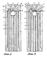
- FIG. 2 is a schematic transverse section of part of the die and core showing particularly the aligning faces in their engaged position during the initial part of an injection moulding, disengagement of the aligning faces being by relative axial movement between the core and die.
- FIG. 3 is a view similar to fig. 2 but showing the core retracted to allow the moulding material to flow between the aligning faces on the core and the mating aligning face on the die.
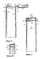
- FIG. 4 is of use similar to fig. 2 but showing particularly the core and die for forming a closed end tube having a captive cap.
- FIG. 5 is a sectional plan on line 5-5 of fig. 4.
- FIG. 6 is a transverse section of a tube formed according to this invention with the captive cap in the position in which it is withdrawn from the die.
- FIG. 7 is a view similar to fig. 6 but showing the captive cap in position to close the end of the tube.
- FIG. 8 is a transverse section of the tube on line 8-8 of fig. 7.
- FIG. 9 is an enlarged view of the end of the tube to show preferred details of construction.
- FIG. 10 is a plan of the tube as shown in fig. 9, and
- FIG. 11 is a fragmentary view of the end of the tube showing the junction of the cap with the body of the tube.
- Referring first particularly to the die and core, the
die 1 can be of any usual or approved construction, preferably built up of a number of metal layers in which the cavities are formed and provided with the necessary temperature regulating and flow means which are not specifically referred to herein as being within the ambit of persons versed in the art of injection moulding. - The
core 2 has in it an axially movable stem having at its inner end an aligningmember 4 which has at its end an aligningface 5 adapted to engage amating aligning face 6 in the die 1. - The die 1 has in it a
central duct 7 through which the moulding material is injected, and this duct opens into the space 8, see Fig. 3, defined by the aligningface 6 whichface 6 is at the perimeter of arecess 9 in the die 1. - The aligning
member 4 has its end of truncated pyramidal form as shown particularly in Fig. 5 but can be in truncated conical form, theface 5 being formed on the end of the aligningmember 4, the aligningmember 4 being movable to cause the end to project to engage in therecess 9. - The face of the aligning
member 4 has in it a series ofchannels 11 which open to theinjection duct 7 and serve to distribute the injection moulding material to the part of theend wall cavity 12 surrounding the aligningfaces die 1 and the face of thecore 2 and hence to thewall cavity 13. - The flow control so achieved allows precise supply of the injection moulding material to all parts of the cavity, including the relatively small-
dimensioned wall cavity 13 of the tube and through a hinge strap cavity to thecap cavity 15. - The
stem 3 is hollow and carries temperature control fluid or fluids to the aligningmember 4. - The die as will be seen defines with the end of the
core 2 theend wall cavity 12 which opens to thewall cavity 13, and thisend wall cavity 12 opens to anozzle cavity 16. Thecap cavity 15 opens to aseal cavity 17. - A
groove 18 is used to facilitate flow down thethin wall cavity 13. - The means for moving the aligning
member 4 through thestem 3 can take any usual or approved form and its operation can be computer timed to ensure a correct sequence, using pressure and/or temperature sensing if required. - The
hinge strap cavity 14 has ends 19 from which the cavity is directed generally in the plane of thewall cavity 13 and the rim of thecap cavity 15 so that the curved generally semi-circular shape shown results whereby stress at the two ends of the strap is minimised. - As described herein, the arrangement allows the
channels 11 which lead from themain injection duct 7 on the axis of thecore 2 to be varied in size to encourage correct flow velocity in different directions and for instance this can ensure the extra flow to thecap cavity 15 through thehinge strap cavity 14. - Describing now the dispenser itself which is formed between the
die 1 andcore 2, theend wall 20 formed in theend wall cavity 12 has therecess 9 formed in it which has inwardly slopingface 5 formed at its periphery, thewall 22 of the tube formed in thewall cavity 13 extending generally axially from theend wall 20. It is the length of this which causes core shift at the inner end of the moulding cavity, which shift is prevented by the arrangement described. - The
cap 23 is attached to theend wall 20 by thehinge strap 24 which is formed by flow through thehinge strap cavity 14, which hingestrap 24 is of relatively substantial dimension to ensure correct flow and is preferably of a length such and is curved when the cap is open so that the hinge part allows the cap to be moved readily away from its sealing position on the end of the tube during normal use. The cap feed can be enhanced by a channel bridging thestrap 24. Thehinge strap 24 folds into arecess 25 in thecap 23 when thecap 23 is swung over from its open and its moulding position into its closed position and because of the relative length of thecurved hinge strap 24, while thehinge strap 24 is not visible as a projection when the tube is sealed allows a neat and highly effective construction to be achieved and allows the tube to be formed so that thecap 23 can lock into position by having anengaging rim 26 on it which engage arecess 27 in the periphery of theend wall 20 to form a lock sufficient to hold thecap 23 firmly in place but allowing thecap 23 to be opened when the content of the tube is to be ejected. - The
discharge nozzle 28 is positioned remotely of thehinge strap 24 and thecap 23 carries asealing socket 29 which fits over thenozzle 28 and thesocket 29 andnozzle 28 hascircumferential undulations 30 so that when thepocket 29 is engaged on thenozzle 28 as thecap 23 is positioned in its closing location thecap 23 is guided into its final position and forms an effective seal not only of the outlet of the nozzle but of the whole of the area surrounding the nozzle to maintain hygenic conditions. - To facilitate ease of positioning of the cap the end wall has an outwardly extending
guide member 31 adjacent to thehinge strap 24 which is adapted to engage a correspondinglyshaped slit 32 on thecap 23 adjacent to thehinge strap 24 so that as thecap 23 is swung over and thehinge strap 24 is accommodated in theengaging slit 32 in the cap, the cap has that end firmly located by theupstanding guide member 31 to ensure that it readily engages thenozzle 28 and the periphery of theend wall 20 and this ensures that thecap 23 does not require holding means around its periphery adjacent to thehinge strap 24 but the holding means can be remote from this as theupstanding guide members 31 firmly locates the hinge end of thecap 23 against sideways displacement while at the other end thenozzle 28 forms the guide and also the holding means but acting in association with the shaped engagingrim 26 fitting into therecess 27 remotely of thehinge strap 24. - In the drawings the part of the
end wall 20 which is formed after thecore 2 and die 1 are relatively moved during extrusion is designated 33. - The
discharge nozzle 28 has a break-away end 34 which on being rotated fractures at 35 to open thenozzle 28. - The
groove 18 leaveslongitudinal ridges 36 on the inner face of thewall 22. - As stated earlier the described method and apparatus can be generally applied where a problem exists in maintaining a core in correct position in relation to a die and need not necessarily be limited to the formation of a tube as defined herein, the particular mating aligning members forming a highly advantageous form of flow control because when the two aligning faces are fully engaged the flow from the main injection channel is through channels radiating through the interengaging arrangement so that initially the injection in the various directions is closely controlled but before injection is completed relatively axial movement between the dies is effected so that the end of, for instance, a toothpaste tube, can be closed by the completion of an end wall of the tube as defined herein, which
end closure 20 may have a sealed or open discharge nozzle. - The
hinge strap 24, as referred to earlier herein, is specially formed to be in therecess 25. Theterminal portions 37 ensure that the bending stress is distributed over the cured part and not taken by acute angles and the ends. Theportions 37 ensure that the hinge strap is stressed into therecess 25 where thecap 23 is closed onto theend closure 20.
Claims (10)
- The method of manufacturing a dispenser for viscous or semi-viscous materials in which the dispenser is in the form of a tube (22) having an end wall (20) and, extending from the perimeter thereof a generally tubular wall adapted after filing to be closed at its other end, in which method an elongated core (2) is projected in the hollow of a die (1) and has its outer end stabilised by engaging an aligning face (5) on the core (2) with a mating aligning face (6) on the die (1), plastic material is injected into the cavity defined between the core (2) and the die (1) to fill the cavity and the core (2) is withdrawn from its engagement with the die (1) while continuing the flow of the plastic material to complete the end wall between the core (2) and the die (1) whereby the part of the end wall (20) surrounding the aligning faces (5, 6) and the wall (22) of the tube are formed while the core (2) is stabilised by the aligning faces (5 and 6) and the formation of the end wall is completed when the aligning face (5) on the core (2) is withdrawn from the aligning face (6) of the die (1), characterised by the steps of:a) injecting flowable plastic material through a duct (7) formed in the die (1) to the end face of the core (2) within the area (8) defined by the mating aligning faces (5 and 6), andb) selectively distributing the flow by means of channels (11) in the end face of the core (2) into the part of the end wall cavity (12) surrounding the aligning faces (5, 6) and the wall cavity (13) between the core (2) and die (1).
- The method of claim 1, wherein the core (2) is stabilised by positioning an axially moveable aligning core member (4) in the core (2) to bring the aligning face (5) which is on the core member (4), into engagement with the aligning face (6).
- The method of claim 2, wherein the end wall includes a cap (23) attached by a hinge (14) to the end wall to cover the end wall, and a cap cavity (15) communicating through a hinge strap cavity (14) with the end wall cavity (12) is formed in step (b), the flow also being selectively distributed through the hinge strap cavity (14) to the cap cavity (15) and the hinge strap (24) and the cap (23) also being formed while the core (2) is stabilised by the aligning core member (4).
- A die and core assembly for the manufacture of a dispenser for viscous or semi-viscous materials in which a hollow in a die (1) has projecting into it a core (2) to form between them a tubular wall cavity (13) and an end wall cavity (12), the tubular wall cavity (13) extending from the perimeter of the end wall cavity (12) to form the wall and the end wall of an elongated hollow body of the dispenser, the core being adapted to be positioned in the die (1) throughout the moulding operation to define the cavities (12, 13), the assembly including an aligning face (5) on the core (2) sloping in relation to the axis of the core (2), a mating aligning face (6) on the die (1) adapted to engage the sloping aligning face (5) on the core (2) axially to align the core (2) in the die (1) during the initial moulding process to form the tube wall (22) and the part of the end wall (20) surrounding the aligning faces (5, 6) but being adapted to disengage during the final moulding process to complete the formation of the end wall (20), characterised by channels (11) in the end of the core (2) between a injection duct (7) within the area (8) defined by the mating aligning faces (5 and 6) and the part of the end wall cavity (12) arranged selectively to direct the flow of moulding material into the cavities (12, 13).
- A means according to claim 4, wherein the core (2) includes an axially moveable aligning core member (4) having the aligning face (5).
- A means according to claim 4 or 5, wherein the cap cavity (15) is also formed between the hollow in the die (1) and the core (2), the cap cavity (15) communicating with the end wall cavity (12) by a hinge cavity (14) whereby a cap (23) is attached to the body by a hinge strap (24).
- Means according to claim 6, wherein the hinge cavity (14) is of elongated form to form a hinge strap (24) and the ends of the strap cavity (14) are in the general plane of the wall cavity (13) and the perimeter wall of the cap cavity (15), the strap cavity (14) being of a generally semi-circular form.
- Means according to claim 6 or 7, wherein the cap (23) is dimensioned to extend over the end wall (20) and wherein the core (2) and die (1) form a discharge nozzle (28) on the end wall (20) remote from the hinge strap (24), and a nozzle sealing socket (29) on the cap (23) positioned to engage over the discharge nozzle (28) when the cap (23) is positioned over the end wall (20), and undulating means (30) on the discharge nozzle (28) and the socket (29) releasably to lock the cap (23) to the end wall (20).
- Means according to claim 6, 7 or 8, characterised by a guide member (31) upstanding on the end wall (20) adjacent to the hinge strap (24), and a split (32) formed on the cap (23) adjacent to the hinge strap (24) positioned to engage over the guide member (31) whereby to facilitate engagement of the discharge nozzle sealing socket (29) over the discharge nozzle (28).
- Means according to any one of the claims 6 to 9, wherein in the die (1) forms an engaging rim (26) on the cap (23) remote from the hinge strap (24) and a mating recess (27) at the perimeter of the end member (2) releasably to lock the cap (23) on the end wall (20) when the cap is engaged on the end wall (20).
Applications Claiming Priority (2)
| Application Number | Priority Date | Filing Date | Title |
|---|---|---|---|
| AUPG935785 | 1985-02-19 | ||
| AU9357/85 | 1985-02-19 |
Publications (3)
| Publication Number | Publication Date |
|---|---|
| EP0216807A1 EP0216807A1 (en) | 1987-04-08 |
| EP0216807A4 EP0216807A4 (en) | 1989-03-06 |
| EP0216807B1 true EP0216807B1 (en) | 1992-12-23 |
Family
ID=3770947
Family Applications (1)
| Application Number | Title | Priority Date | Filing Date |
|---|---|---|---|
| EP86901301A Expired EP0216807B1 (en) | 1985-02-19 | 1986-02-13 | Method of and means for manufacture of a dispenser for viscous or semi-viscous materials |
Country Status (7)
| Country | Link |
|---|---|
| US (1) | US4733801A (en) |
| EP (1) | EP0216807B1 (en) |
| AU (1) | AU576070B2 (en) |
| CA (1) | CA1262023A (en) |
| DE (1) | DE3687334T2 (en) |
| NZ (1) | NZ215120A (en) |
| WO (1) | WO1986004856A1 (en) |
Families Citing this family (33)
| Publication number | Priority date | Publication date | Assignee | Title |
|---|---|---|---|---|
| US5447674A (en) * | 1987-06-04 | 1995-09-05 | Schellenbach; Frank | Method for producing a gas-tight plastic closure for containers |
| DE418279T1 (en) * | 1988-06-02 | 1996-09-19 | Jens Ole Sorensen | REDUCTION OF THE REQUIRED CLAMPING FORCE AND CONTROL OF THE WALL THICKNESS OF AN INJECTION MOLDING PART. |
| US5049344A (en) * | 1988-06-02 | 1991-09-17 | Primtec | Method for reducing required mold-cavity clamping force and controlling injection-molded-product wall thickness |
| US5174941A (en) * | 1988-06-02 | 1992-12-29 | Primtec | Injection-molding product wall-thickness control methods |
| US4856977A (en) * | 1988-07-01 | 1989-08-15 | Holdt J W Von | Two stage mold centering system |
| US4941580A (en) * | 1989-05-26 | 1990-07-17 | Sunbeam Plastics Corporation | Dispensing closure |
| SE9002310D0 (en) * | 1990-07-02 | 1990-07-02 | Norden Packaging Mach | DISPOSABLE CONTAINER FOR SINGLE DOSAGE APPLICATIONS |
| WO1992005024A1 (en) * | 1990-09-24 | 1992-04-02 | Ian Orde Michael Jacobs | Apparatus for injection moulding thin-walled containers |
| FR2691096A1 (en) * | 1992-05-13 | 1993-11-19 | Cristour Sa | Method of injection molding of several different plastic materials from a decorative cord capsule and capsule obtained by this method. |
| FR2731983B1 (en) * | 1995-03-20 | 1997-05-09 | Momiplast Sa | CLOSURE CAPSULE WITH PERIPHERAL HINGE AND INJECTION MOLDING DEVICE FOR MAKING THIS CLOSURE CAPSULE WITH A SINGLE PIECE |
| FR2736329B1 (en) * | 1995-07-05 | 1997-08-29 | Astra Plastique | CLOSING CAPE PROVIDED WITH A DEGASSING DEVICE, METHOD FOR MANUFACTURING SUCH A CAPE AND DEVICE FOR CARRYING OUT SAID METHOD |
| DE19703316B4 (en) * | 1997-01-30 | 2008-06-05 | Fischbach Kg Kunststoff-Technik | Method and device for producing a nozzle cartridge |
| EP1048582A1 (en) * | 1999-04-29 | 2000-11-02 | Createchnic AG | Plastic tube provided with a hinged closure and method of making the same |
| FR2806345B1 (en) * | 2000-03-17 | 2002-11-29 | Cep Ind | MOLD FOR INJECTION OF A FLEXIBLE TUBE, AND INJECTION METHOD |
| DE60116088T2 (en) * | 2000-05-25 | 2006-07-13 | CROWN Packaging Technology, Inc, Alsip | ISSUE CLOSURE |
| US6495089B1 (en) * | 2000-07-18 | 2002-12-17 | Graham Packaging Company, L.P. | Blow-molded container and closure, and method and apparatus for making same |
| AR034176A1 (en) | 2000-11-08 | 2004-02-04 | Graham Packaging Pet Tech | METHOD OF PRODUCTION OF A PLASTIC CONTAINER IN A COMPRESSIBLE TUBE, INTERMEDIATE ARTICLE FOR USE IN THE FORMATION OF A PLASTIC CONTAINER IN A COMPRIMIBLE TUBE, AND PLASTIC CONTAINER IN A COMPRIMIBLE TUBE |
| US6555033B2 (en) * | 2001-06-27 | 2003-04-29 | Graham Packaging Company, L.P. | Method and apparatus for making a plastic container and closure combination |
| BR0309842A (en) * | 2002-05-08 | 2005-03-15 | Graham Packaging Co | Two-piece vertical tube that can be compressed |
| CA2490582A1 (en) * | 2002-07-02 | 2004-01-15 | Bormioli Rocco & Figlio S.P.A. | A plastic single-piece tube |
| US20040108342A1 (en) * | 2002-12-04 | 2004-06-10 | Graham Packaging Company, L.P. | One piece push-pull cap for plastic containers |
| DE10333160A1 (en) * | 2003-07-22 | 2005-02-10 | Fischbach Kg Kunststoff-Technik | Flexible tube, is formed by injection molding a tube blank, and removing the blank by pulling out the core while holding the head, then pulling back the mold |
| US20050098582A1 (en) * | 2003-11-12 | 2005-05-12 | Graham Packaging Company | Stand-up tube with a dispensing nose |
| US7169342B1 (en) | 2004-03-31 | 2007-01-30 | Sorensen Research And Development Trust | Injection molding of tubular plastic products |
| US7510095B2 (en) | 2005-03-11 | 2009-03-31 | Berry Plastics Corporation | System comprising a radially aligned container and closure |
| US8308465B2 (en) * | 2007-06-13 | 2012-11-13 | Injectnotech Inc. | Wedge-lock system for injection molds |
| EP2002951B1 (en) * | 2007-06-13 | 2010-08-18 | Top Grade Molds Ltd. | Wedge lock system for injection molds |
| US20090095769A1 (en) * | 2007-10-15 | 2009-04-16 | Roei Avraham | Collapsible tube with roll-up fastener structure |
| EP2532602A1 (en) * | 2011-06-07 | 2012-12-12 | Nestec S.A. | A one-piece closure for equipping a container |
| USD958208S1 (en) | 2019-06-04 | 2022-07-19 | Husky Injection Molding Systems Ltd. | Molding machine part |
| US12325108B1 (en) * | 2022-02-22 | 2025-06-10 | Robert Everett Ford | Supplement support system sleeve for a universal joint improvements / angled flex stop |
| FR3153601B1 (en) * | 2023-09-29 | 2025-12-05 | Albea Services | SINGLE-MATERIAL TUBE EQUIPPED WITH AN OVAL-SHAPED TUBE HEAD |
| FR3153602B1 (en) * | 2023-09-29 | 2025-10-24 | Albea Services | Tube head having an oval shape and tube comprising said tube head |
Family Cites Families (11)
| Publication number | Priority date | Publication date | Assignee | Title |
|---|---|---|---|---|
| US2252090A (en) * | 1938-06-15 | 1941-08-12 | Whitehall Patents Corp | Means and method of forming separable fastener stringers |
| US2822578A (en) * | 1956-09-06 | 1958-02-11 | George M Lobell | Injection-moulding apparatus |
| DE1166457B (en) * | 1960-11-10 | 1964-03-26 | Josef Wischerath Kommanditgese | Injection molding tool for the production of molded parts |
| CH451494A (en) * | 1966-07-15 | 1968-05-15 | Segmueller Ag | Process for the production of cup-shaped or sleeve-shaped containers made of thermoplastics by injection molding |
| US3537676A (en) * | 1967-12-20 | 1970-11-03 | Valve Corp Of America | Mold apparatus for closure with integral cap |
| US4071532A (en) * | 1973-12-21 | 1978-01-31 | Heidenreich & Harbeck Zweigniederlassung Der Gildemeister Ag | Method for manufacturing plastics blanks |
| CH595969A5 (en) * | 1975-06-13 | 1978-02-28 | Ennio Glauco Curetti | |
| US4261486A (en) * | 1979-08-06 | 1981-04-14 | Sunbeam Plastics Corporation | One-piece dispensing closure with lid hold-open feature |
| WO1981001544A1 (en) * | 1979-11-30 | 1981-06-11 | Scammell J | Dispenser for viscous or semi-viscous materials |
| US4465651A (en) * | 1981-07-01 | 1984-08-14 | American Can Company | Apparatus and process for molding a thermoplastic tube headpiece |
| US4508676A (en) * | 1982-07-29 | 1985-04-02 | Sorensen Jens Ole | Core stabilization by sequential injections |
-
1986
- 1986-02-11 NZ NZ215120A patent/NZ215120A/en unknown
- 1986-02-13 DE DE8686901301T patent/DE3687334T2/en not_active Expired - Fee Related
- 1986-02-13 AU AU55124/86A patent/AU576070B2/en not_active Ceased
- 1986-02-13 US US06/939,125 patent/US4733801A/en not_active Expired - Fee Related
- 1986-02-13 EP EP86901301A patent/EP0216807B1/en not_active Expired
- 1986-02-13 WO PCT/AU1986/000036 patent/WO1986004856A1/en not_active Ceased
- 1986-02-18 CA CA000502084A patent/CA1262023A/en not_active Expired
Also Published As
| Publication number | Publication date |
|---|---|
| WO1986004856A1 (en) | 1986-08-28 |
| NZ215120A (en) | 1986-12-05 |
| CA1262023A (en) | 1989-10-03 |
| AU576070B2 (en) | 1988-08-11 |
| DE3687334D1 (en) | 1993-02-04 |
| EP0216807A4 (en) | 1989-03-06 |
| AU5512486A (en) | 1986-09-10 |
| DE3687334T2 (en) | 1993-06-09 |
| US4733801A (en) | 1988-03-29 |
| EP0216807A1 (en) | 1987-04-08 |
Similar Documents
| Publication | Publication Date | Title |
|---|---|---|
| EP0216807B1 (en) | Method of and means for manufacture of a dispenser for viscous or semi-viscous materials | |
| EP0442379B1 (en) | A stopper for deformable containers, incorporating an elastic diaphragm dispenser with a self-closing orifice, and method for the manufacture thereof | |
| EP0040615B1 (en) | Dispenser for viscous or semi-viscous materials | |
| CA2028606C (en) | Dispensing bottle with coupling between closure head and screw cap | |
| US4925128A (en) | Spout for squeeze bottle | |
| US6938787B2 (en) | Synthetic-resin screw cap | |
| US5975381A (en) | Dispensing cap equipped with a stopper, and method of manufacturing this cap | |
| CA2357098C (en) | Tamper-indicating closure with resilient locking projections | |
| EP1227892B1 (en) | Hot-runner nozzle for injection moulding | |
| US4540542A (en) | Method for making a container with a unitary but removable closure | |
| CZ204095A3 (en) | Closure of a container, process of its manufacture, closure assembly and a mould for making the same | |
| CN101014508A (en) | Container closure and method of assembly | |
| US4632265A (en) | Press-on cap and seal | |
| US4564113A (en) | Injection molded plastic closure | |
| US4830214A (en) | One-piece molded end closure | |
| US4726925A (en) | Molding of elongate plastic cylinders | |
| US3150220A (en) | Method of making applicator-type containers | |
| USRE33764E (en) | Press-on cap and seal | |
| US5037290A (en) | Apparatus for molding a one-piece molded end closure | |
| US5199605A (en) | Creamy or pasty product dispenser with a rotationally controlled aperture in the cap and with safety means against uncontrolled opening | |
| JPH09155933A (en) | Resin flexible nozzle and injection molding method of hollow material in continuous form | |
| EP1024091A1 (en) | Removable tip dispensing closure and method of manufacture | |
| US6077471A (en) | Mold for forming a container having a continuous neck finish and method for using same | |
| EP0329881A1 (en) | Self-draining container | |
| HK1000592B (en) | Self-draining container |
Legal Events
| Date | Code | Title | Description |
|---|---|---|---|
| PUAI | Public reference made under article 153(3) epc to a published international application that has entered the european phase |
Free format text: ORIGINAL CODE: 0009012 |
|
| 17P | Request for examination filed |
Effective date: 19861029 |
|
| AK | Designated contracting states |
Kind code of ref document: A1 Designated state(s): DE GB |
|
| A4 | Supplementary search report drawn up and despatched |
Effective date: 19890306 |
|
| 17Q | First examination report despatched |
Effective date: 19900511 |
|
| GRAA | (expected) grant |
Free format text: ORIGINAL CODE: 0009210 |
|
| AK | Designated contracting states |
Kind code of ref document: B1 Designated state(s): DE GB |
|
| REF | Corresponds to: |
Ref document number: 3687334 Country of ref document: DE Date of ref document: 19930204 |
|
| PLBE | No opposition filed within time limit |
Free format text: ORIGINAL CODE: 0009261 |
|
| STAA | Information on the status of an ep patent application or granted ep patent |
Free format text: STATUS: NO OPPOSITION FILED WITHIN TIME LIMIT |
|
| 26N | No opposition filed | ||
| PGFP | Annual fee paid to national office [announced via postgrant information from national office to epo] |
Ref country code: GB Payment date: 19940201 Year of fee payment: 9 |
|
| PGFP | Annual fee paid to national office [announced via postgrant information from national office to epo] |
Ref country code: DE Payment date: 19940224 Year of fee payment: 9 |
|
| PG25 | Lapsed in a contracting state [announced via postgrant information from national office to epo] |
Ref country code: GB Effective date: 19950213 |
|
| GBPC | Gb: european patent ceased through non-payment of renewal fee |
Effective date: 19950213 |
|
| PG25 | Lapsed in a contracting state [announced via postgrant information from national office to epo] |
Ref country code: DE Effective date: 19951101 |