EP0216379A2 - Communication method and equipment therefor - Google Patents
Communication method and equipment therefor Download PDFInfo
- Publication number
- EP0216379A2 EP0216379A2 EP86113186A EP86113186A EP0216379A2 EP 0216379 A2 EP0216379 A2 EP 0216379A2 EP 86113186 A EP86113186 A EP 86113186A EP 86113186 A EP86113186 A EP 86113186A EP 0216379 A2 EP0216379 A2 EP 0216379A2
- Authority
- EP
- European Patent Office
- Prior art keywords
- transmission
- frame
- time
- communication equipment
- section
- Prior art date
- Legal status (The legal status is an assumption and is not a legal conclusion. Google has not performed a legal analysis and makes no representation as to the accuracy of the status listed.)
- Granted
Links
Images

Classifications
-
- H—ELECTRICITY
- H04—ELECTRIC COMMUNICATION TECHNIQUE
- H04L—TRANSMISSION OF DIGITAL INFORMATION, e.g. TELEGRAPHIC COMMUNICATION
- H04L12/00—Data switching networks
- H04L12/28—Data switching networks characterised by path configuration, e.g. LAN [Local Area Networks] or WAN [Wide Area Networks]
- H04L12/40—Bus networks
- H04L12/407—Bus networks with decentralised control
- H04L12/413—Bus networks with decentralised control with random access, e.g. carrier-sense multiple-access with collision detection (CSMA-CD)
-
- H—ELECTRICITY
- H04—ELECTRIC COMMUNICATION TECHNIQUE
- H04L—TRANSMISSION OF DIGITAL INFORMATION, e.g. TELEGRAPHIC COMMUNICATION
- H04L12/00—Data switching networks
- H04L12/28—Data switching networks characterised by path configuration, e.g. LAN [Local Area Networks] or WAN [Wide Area Networks]
- H04L12/40—Bus networks
- H04L12/40143—Bus networks involving priority mechanisms
Definitions
- the present invention relates to a communication method using a small scale computer network and a communication equipment used therefor.
- the present invention is concerned with a communication method and an equipment therefor capable of accumulating a plurality of communication data (which will be called "frames" hereinafter) at the same time to optionally change transmission interval between frames when they are transmitted to the network in sequence, thereby eliminating the possibility that only a specified communication station occupies the network.
- frames which will be called "frames" hereinafter
- CSMA/CD Carrier Sense Multiple Access with Collision Detection
- a single coaxial cable is used as a transmission medium and all communication equipments are connected in parallel with the medium.
- a judgement as to whether transmission signals by other communication equipments are present or not on the medium is made. Only when such transmission signals are absent, transmission is enabled and when it is recognized that other communication equipments except for the self-station or self-equipment effect transmission substantially at the same time, transmission is interrupted to make a judgement for a second time as to whether the above-mentioned transmission signals are present or absent.
- the communication equipment operates so as to transmit frames at minimum time intervals. Accordingly, frames will be transmitted one after another on the network medium every minimum inter frame time (which will be called "IFS (Inter Frame Spacing) time” hereinafter).
- IFS Inter Frame Spacing
- this communication equipment when there is a frame to be transmitted in other communication equipment on the network, this communication equipment also initiates transmission of the self-frame when the IFS time has elapsed after the frame disappears on the network. In this instance, two communication equipments will effect transmission of frames substantially at the same time. As a result, these frames collide with each other and the contents thereof are broken. Thus, it is necessary to again restart the transmission procedure from the stage of the carrier sense, giving rise to the problem that efficiency in use of the network is extremely lowered.
- An object of the present invention is to provide a communication equipment having a function to transmit a plurality of frames in succession, the communication equipment being operated to optionally change the time interval from the time when a frame has been transmitted to the time when the next frame is transmitted, thereby to prevent frames transmitted from other communication equipments from being broken thus to prevent efficiency in use of the network from being lowered.
- a communication method is characterized in that each communication equipment initiates occurrence of transmission delay instruction after frame transmission is completed, terminates the occurrence of said transmission delay instruction when either the condition that a predetermined time has elapsed from the time when transmission is completed or the condition that reception of any frame from other communication equipment is completed is satisfied, and initiates transmission of the next frame, provided that the occurrence of said transmission delay instruction has been terminated.
- a communication equipment comprises a timer section for counting a predetermined time given from the external after transmission of a frame is completed, a carrier sense section for sensing the fact that any frame transmitted from other communication equipment is being received, and a transmission delay flag section for instructing a transmission section which transmits frames to delay transmission of the frame, occurrence of the transmission delay instruction being initiated when transmission of a frame is completed, the transmission delay instruction being terminated in response to either of two facts which has occurred earlier, one fact being that the timer section has counted the predetermined time, the other fact being that reception of any frame transmitted from other communication equipment is detected in the detection section, the transmission section initiating transmission of a frame upon completion that the transmission delay instruction is absent prior to the initiation of transmission.
- the communication equipment in this embodiment comprises a transmission section 1 which manages and executes transmission of frames, a timer 2 which counts or measures a predetermined time after transmission of the frame is completed, a carrier sense section 3 which senses the fact that any frame is being transmitted from other communication equipment, a network adapter 4 for transmitting frames from the transmission section 1 to a network medium 14 and for receiving signals from the network medium 14, and a transmission delay flag section 5 responsive to signals from the timer 2 and the carrier sense section 3 to generate a transmission delay signal (which will be simply referred to as "DELAY signal" hereinafter) 8.
- a transmission delay signal which will be simply referred to as "DELAY signal” hereinafter
- the transmission section 1 when a frame is transmitted, the DELAY signal 8 is checked prior to the transmission. As a result, when the DELAY signal 8 represents logical "0", the transmission section 1 judges this state as the transmission enable state. In addition to this judgement result, when the condition that the IFS time has elapsed (which will be described later) is satisfied, the transmission section 1 initiates transmission of the frame. In contrast, when the DELAY signal 8 represents logical "1", the transmission section 1 prolongs or delays the transmission of the frame until the DELAY signal shifts to logical "0".
- the transmission section 1 sets a signal 11 indicating that transmission is being effected (which will be simply referred to as "TXON signal” hereinafter) to logical "1" during transmission and sets the TXON signal 11 to logical "0" at a time period during which transmission is not conducted.
- the transmission section 1 outputs a pulse of logical "1" on a line for a TXDONE signal 15 when the transmission of the frame is completed.
- the carrier sense section 3 inputs the TXON signal 11 and a reception data signal 10 and judges that the frame is present on the network medium 14 when the TXON signal 11 represents logical "0" and data appears on the reception data signal 10 to output a carrier sense signal 13.
- time T1 When the TXON signal 11 is input and the logical level of this signal shifts from "1" to"0", i.e., when transmission of the frame is completed, the timer 2 is activated. After a time (which will be called “time T1" hereinafter) set by setting means (not shown) has elapsed, the timer 2 outputs a pulse of logical "1" on a line for a timer signal 12.
- the transmission delay flag section 5 is configured so that the TXDONE signal 15, the timer signal 12 and the carrier sense signal 13 are input thereto.
- the TXDONE signal 15 is connected to a set input of a RS type flip-flop (which will be called a "RS F/F” hereinafter) and the DELAY signal 8 is set to logical "1" when transmission of the frame is completed.
- RS F/F RS type flip-flop
- the DELAY signal 8 is set to logical "1" when transmission of the frame is completed.
- logical sum of the timer signal 12 and the carrier sense signal 13 is performed at an OR circuit 7.
- the OR circuit 7 has an output connected to a reset input of the RS F/F 6.
- this communication equipment initiates transmission of the first frame A.
- the frame A being transmitted appears on the reception data signal 10, but the TXON signal represents logical "1", with the result that the carrier sense signal 13 remains at logical "0".
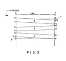
- Fig. 3 shows the relationship between propagation time of a signal in the LAN and distance between communication equipment where abscissa and ordinate represent distance and time elapsed, respectively. It is assumed that communication equipments S and T are most distant from each other in this LAN and symbols t4 to t9 and t4' to t9' representative of times correspond to those t4 to t9 in Fig. 2, respectively.
- frame B (corresponding to the frame B in Fig. 2) transmitted from the communication equipment S is propagated at a finite speed within the network medium and is received at the communication equipment T at time t4'.
- This time (t1' - t4) is referred to as the maximum propagation delay time ⁇ .
- the time t5' when the communication equipment T detects that transmission of the frame B has been completed at the communication equipment S (at time t5) is represented by (T5 + ⁇ ).
- transmission of the frame X is initiated at time t6 when IFS time has passed and this frame X is received at time t6 when time ⁇ has passed at the communication equipment S.
- time T1 is set to values different from each other, it is possible to change order of priority related to use of the network by each communication equipment. Generally, the longer the time T1 is, the more order of priority lowers.
- the communication system according to the present invention is configured above, with the result that the next frame cannot be transmitted within the time T1, for example, after the self-frame has been transmitted at the communication equipment S.
- the frame B cannot be transmitted immediately after the frame A in Fig. 2.
- the frame from the communication equipment T has priority to frames from the communication equipment S, resulting in no possibility that this frame is broken by the frame to be transmitted from the communication equipment S next time.
- the frame X from the communication equipment T will be normally transmitted subsequently to the frame B.
- the frame C is transmitted with a delay of IFS time and the frame X is transmitted also from the communication equipment T substantially at the same time.
- these two frames collide with each other, so that both frames are broken. For this reason, post processing time for collision has been required.
- the present invention can avoid collision and wasteful time is not required. Further, with the present invention, there is no possibility that the network medium is wastefully used due to occurrence of collision, thus making it possible to effect data communication having high efficiency.
- the frame received can be immediately transmitted after the IFS time has passed.
- the present invention can advantageously realize data communication having a still more higher efficiency.
Abstract
Description
- The present invention relates to a communication method using a small scale computer network and a communication equipment used therefor. particularly, the present invention is concerned with a communication method and an equipment therefor capable of accumulating a plurality of communication data (which will be called "frames" hereinafter) at the same time to optionally change transmission interval between frames when they are transmitted to the network in sequence, thereby eliminating the possibility that only a specified communication station occupies the network.
- For one of communication systems to construct LAN (Local Area Network) which is the small scale computer network, there is known CSMA/CD (Carrier Sense Multiple Access with Collision Detection) system. According to this sytem, a single coaxial cable is used as a transmission medium and all communication equipments are connected in parallel with the medium. A judgement as to whether transmission signals by other communication equipments are present or not on the medium is made. Only when such transmission signals are absent, transmission is enabled and when it is recognized that other communication equipments except for the self-station or self-equipment effect transmission substantially at the same time, transmission is interrupted to make a judgement for a second time as to whether the above-mentioned transmission signals are present or absent.
- There is a tendency that communication equipment for realizing such a communication system is constituted with an LSI dedicated thereto. The feature of such an LSI resides in that the LSI has a function to input a plurality of data related to frames to be transmitted in advance as control data thereby to transmit frames in succession.
- However, when the LSI has such a function, the communication equipment operates so as to transmit frames at minimum time intervals. Accordingly, frames will be transmitted one after another on the network medium every minimum inter frame time (which will be called "IFS (Inter Frame Spacing) time" hereinafter).
- On the other hand, when there is a frame to be transmitted in other communication equipment on the network, this communication equipment also initiates transmission of the self-frame when the IFS time has elapsed after the frame disappears on the network. In this instance, two communication equipments will effect transmission of frames substantially at the same time. As a result, these frames collide with each other and the contents thereof are broken. Thus, it is necessary to again restart the transmission procedure from the stage of the carrier sense, giving rise to the problem that efficiency in use of the network is extremely lowered.
- An object of the present invention is to provide a communication equipment having a function to transmit a plurality of frames in succession, the communication equipment being operated to optionally change the time interval from the time when a frame has been transmitted to the time when the next frame is transmitted, thereby to prevent frames transmitted from other communication equipments from being broken thus to prevent efficiency in use of the network from being lowered.
- A communication method according to the present invention is characterized in that each communication equipment initiates occurrence of transmission delay instruction after frame transmission is completed, terminates the occurrence of said transmission delay instruction when either the condition that a predetermined time has elapsed from the time when transmission is completed or the condition that reception of any frame from other communication equipment is completed is satisfied, and initiates transmission of the next frame, provided that the occurrence of said transmission delay instruction has been terminated.
- A communication equipment according to the present invention comprises a timer section for counting a predetermined time given from the external after transmission of a frame is completed, a carrier sense section for sensing the fact that any frame transmitted from other communication equipment is being received, and a transmission delay flag section for instructing a transmission section which transmits frames to delay transmission of the frame, occurrence of the transmission delay instruction being initiated when transmission of a frame is completed, the transmission delay instruction being terminated in response to either of two facts which has occurred earlier, one fact being that the timer section has counted the predetermined time, the other fact being that reception of any frame transmitted from other communication equipment is detected in the detection section, the transmission section initiating transmission of a frame upon completion that the transmission delay instruction is absent prior to the initiation of transmission.
- In the accompanying drawings:
- Fig. 1 is a block diagram illustrating a communication equipment according to the present invention;
- Fig. 2 is a timing chart showing the operation of the communication equipment to which the present invention is applied; and
- Fig. 3 is an explanatory view showing propagation of a frame on the network employed in the communication equipment of the invention.
-
- A preferred embodiment of a communication equipment according to the present invention will be described with reference to Fig. 1.
- The communication equipment in this embodiment comprises a
transmission section 1 which manages and executes transmission of frames, atimer 2 which counts or measures a predetermined time after transmission of the frame is completed, a carrier sense section 3 which senses the fact that any frame is being transmitted from other communication equipment, anetwork adapter 4 for transmitting frames from thetransmission section 1 to anetwork medium 14 and for receiving signals from thenetwork medium 14, and a transmissiondelay flag section 5 responsive to signals from thetimer 2 and the carrier sense section 3 to generate a transmission delay signal (which will be simply referred to as "DELAY signal" hereinafter) 8. - In the
transmission section 1, when a frame is transmitted, theDELAY signal 8 is checked prior to the transmission. As a result, when the DELAYsignal 8 represents logical "0", thetransmission section 1 judges this state as the transmission enable state. In addition to this judgement result, when the condition that the IFS time has elapsed (which will be described later) is satisfied, thetransmission section 1 initiates transmission of the frame. In contrast, when theDELAY signal 8 represents logical "1", thetransmission section 1 prolongs or delays the transmission of the frame until the DELAY signal shifts to logical "0". Thetransmission section 1 sets a signal 11 indicating that transmission is being effected (which will be simply referred to as "TXON signal" hereinafter) to logical "1" during transmission and sets the TXON signal 11 to logical "0" at a time period during which transmission is not conducted. In addition, thetransmission section 1 outputs a pulse of logical "1" on a line for aTXDONE signal 15 when the transmission of the frame is completed. Further, the carrier sense section 3 inputs the TXON signal 11 and areception data signal 10 and judges that the frame is present on thenetwork medium 14 when the TXON signal 11 represents logical "0" and data appears on thereception data signal 10 to output acarrier sense signal 13. When the TXON signal 11 is input and the logical level of this signal shifts from "1" to"0", i.e., when transmission of the frame is completed, thetimer 2 is activated. After a time (which will be called "time T₁" hereinafter) set by setting means (not shown) has elapsed, thetimer 2 outputs a pulse of logical "1" on a line for atimer signal 12. - The transmission
delay flag section 5 is configured so that theTXDONE signal 15, thetimer signal 12 and thecarrier sense signal 13 are input thereto. The TXDONEsignal 15 is connected to a set input of a RS type flip-flop (which will be called a "RS F/F" hereinafter) and theDELAY signal 8 is set to logical "1" when transmission of the frame is completed. In addition, logical sum of thetimer signal 12 and thecarrier sense signal 13 is performed at an OR circuit 7. The OR circuit 7 has an output connected to a reset input of the RS F/F 6. Thus, when either of thetimer signal 12 and thecarrier sense signal 13 represents logical "1", the DELAY signal is cleared to logical "0". - Flow of the entire signals will be described with reference to Fig. 2. It is assumed that the communication equipment successively transmits four frames labeled A, B, C and D.
- At time t₁, since the DELAY
signal 8 represents logical "0", this communication equipment initiates transmission of the first frame A. The frame A being transmitted appears on thereception data signal 10, but the TXON signal represents logical "1", with the result that thecarrier sense signal 13 remains at logical "0". - At time t₂, since transmission of the frame is completed, a pulse of logical "1" is output on the line for the
TXDONE signal 15. Thus, since theDELAY signal 8 shifts to logical "1" and the TXON signal 11 shifts to logical "0", the timer is activated. Since the DELAYsignal 8 has shifted to logical "1", it is unable to transmit the next frame B. - At time t₃, since the time T₁ has elapsed after the transmission of the frame A is completed, a pulse of logical "1" is output on the line for the
timer signal 12 and theDELAY signal 8 shifts to logical "0". - At time t₄, since the DELAY
signal 8 represents logical "0" and the IFS time has passed from the time when the transmission of the frame A is completed, transmission of the next frame B is initiated. The operation at this time is the same as that at time t₁. - At time t₅, since the transmission of the frame B is completed, the
timer 2 is activated. - At time t₆, reception of a frame X transmitted from any other communication equipment is initiated. At this time, since the TXON signal 11 represents logical "0", the
carrier sense signal 13 shifts to logical "1". In response to the rise of thecarrier detection signal 13, theDELAY signal 8 immediately shifts to logical "0". - At time t₇, reception of the frame X is thus completed. At this time, since the DELAY
signal 8 represents logical "0", transmission of the third frame C can be initiated at time t₈ when IFS time has passed after the reception of the frame X. - The operation at times t₉ to t₁₁ is the same as that at times t₂ to t₄.
- At this time, even when the length of the frame X is shorter than the time T₁, since the
DELAY signal 8 is maintained at logical "0" at time t₆ when reception of the frame X is initiated, it is possible to transmit the frame C after the transmission of the frame B is completed before the time T₁ has passed. In this instance, since the TXON signal represents logical "1" before counting of thetimer 2 is completed, thetimer signal 12 to be output between times t₈ and t₉ is not actually output. - Then, the value of the time T₁ to be set will be described.
- Fig. 3 shows the relationship between propagation time of a signal in the LAN and distance between communication equipment where abscissa and ordinate represent distance and time elapsed, respectively. It is assumed that communication equipments S and T are most distant from each other in this LAN and symbols t₄ to t₉ and t₄' to t₉' representative of times correspond to those t₄ to t₉ in Fig. 2, respectively.
- First, at time t₄, frame B (corresponding to the frame B in Fig. 2) transmitted from the communication equipment S is propagated at a finite speed within the network medium and is received at the communication equipment T at time t₄'. This time (t₁' - t₄) is referred to as the maximum propagation delay time τ. Accordingly, the time t5' when the communication equipment T detects that transmission of the frame B has been completed at the communication equipment S (at time t₅) is represented by (T₅ + τ).
- In the communication equipment T, transmission of the frame X is initiated at time t₆ when IFS time has passed and this frame X is received at time t₆ when time τ has passed at the communication equipment S.
- From the above, the following relationships will be derived.
t₅' = t₅ + τ
t₆' = t₅' + IFS = t₅ + τ + IFS, and
t₆ = t₆' + τ = t₅ + 2τ + IFS.
Namely, this means that the communication equipments are unable to receive the frame transmitted from the most distant communication equipment as long as time (2τ + IFS) has not passed after the communication equipment S has transmitted a frame. - Accordingly, for time T₁ required for normally receiving this frame X, it is necessary to satisfy T₁>(2τ + IFS).
- Further, by setting the time T₁ to values different from each other, it is possible to change order of priority related to use of the network by each communication equipment. Generally, the longer the time T₁ is, the more order of priority lowers.
- The communication system according to the present invention is configured above, with the result that the next frame cannot be transmitted within the time T₁, for example, after the self-frame has been transmitted at the communication equipment S. For instance, the frame B cannot be transmitted immediately after the frame A in Fig. 2. Accordingly, when a frame transmitted immediately from any other communication equipment T upon completion of the frame transmission is reached to the communication equipment within the time T₁, the frame from the communication equipment T has priority to frames from the communication equipment S, resulting in no possibility that this frame is broken by the frame to be transmitted from the communication equipment S next time. For instance, in Fig. 2, the frame X from the communication equipment T will be normally transmitted subsequently to the frame B.
- In the conventional example, when the frame B has been transmitted at the communication equipment S, the frame C is transmitted with a delay of IFS time and the frame X is transmitted also from the communication equipment T substantially at the same time. As a result, these two frames collide with each other, so that both frames are broken. For this reason, post processing time for collision has been required. In contrast, the present invention can avoid collision and wasteful time is not required. Further, with the present invention, there is no possibility that the network medium is wastefully used due to occurrence of collision, thus making it possible to effect data communication having high efficiency.
- In addition, after a frame from any other communication equipment has been received, the frame received can be immediately transmitted after the IFS time has passed. Thus, the present invention can advantageously realize data communication having a still more higher efficiency.
Claims (7)
Applications Claiming Priority (2)
| Application Number | Priority Date | Filing Date | Title |
|---|---|---|---|
| JP213812/85 | 1985-09-27 | ||
| JP60213812A JPS6276341A (en) | 1985-09-27 | 1985-09-27 | Method and apparatus for communication |
Publications (3)
| Publication Number | Publication Date |
|---|---|
| EP0216379A2 true EP0216379A2 (en) | 1987-04-01 |
| EP0216379A3 EP0216379A3 (en) | 1988-07-13 |
| EP0216379B1 EP0216379B1 (en) | 1989-11-23 |
Family
ID=16645439
Family Applications (1)
| Application Number | Title | Priority Date | Filing Date |
|---|---|---|---|
| EP86113186A Expired EP0216379B1 (en) | 1985-09-27 | 1986-09-25 | Communication method and equipment therefor |
Country Status (4)
| Country | Link |
|---|---|
| US (1) | US4901311A (en) |
| EP (1) | EP0216379B1 (en) |
| JP (1) | JPS6276341A (en) |
| DE (1) | DE3667122D1 (en) |
Cited By (1)
| Publication number | Priority date | Publication date | Assignee | Title |
|---|---|---|---|---|
| WO2000036789A2 (en) * | 1998-12-16 | 2000-06-22 | Koninklijke Philips Electronics N.V. | Fairness scheme for a serial interface |
Families Citing this family (2)
| Publication number | Priority date | Publication date | Assignee | Title |
|---|---|---|---|---|
| DE3941476A1 (en) * | 1989-12-15 | 1991-06-20 | Melitta Haushaltsprodukte | CONTINUOUS HEATERS, ESPECIALLY FOR MACHINES FOR THE PRODUCTION OF BREW BEVERAGES |
| US5245609A (en) * | 1991-01-30 | 1993-09-14 | International Business Machines Corporation | Communication network and a method of regulating the transmission of data packets in a communication network |
Citations (4)
| Publication number | Priority date | Publication date | Assignee | Title |
|---|---|---|---|---|
| WO1980001025A1 (en) * | 1978-11-06 | 1980-05-15 | Boeing Co | Autonomous terminal data communication system |
| EP0022170A2 (en) * | 1979-06-29 | 1981-01-14 | International Business Machines Corporation | Method of attaining communication of data packets on a local shared bus network and local shared bus network |
| US4412326A (en) * | 1981-10-23 | 1983-10-25 | Bell Telephone Laboratories, Inc. | Collision avoiding system, apparatus and protocol for a multiple access digital communications system including variable length packets |
| WO1984004862A1 (en) * | 1983-05-27 | 1984-12-06 | American Telephone & Telegraph | Scheme for reducing transmission delay following collision of transmissions in communication networks |
Family Cites Families (4)
| Publication number | Priority date | Publication date | Assignee | Title |
|---|---|---|---|---|
| US4332027A (en) * | 1981-10-01 | 1982-05-25 | Burroughs Corporation | Local area contention network data communication system |
| US4560985B1 (en) * | 1982-05-07 | 1994-04-12 | Digital Equipment Corp | Dual-count, round-robin ditributed arbitration technique for serial buses |
| US4539677A (en) * | 1983-07-28 | 1985-09-03 | International Business Machines Corp. | Multiple access data communication system |
| US4689785A (en) * | 1984-09-14 | 1987-08-25 | Sanyo Electric Co., Ltd. | Data transmission system |
-
1985
- 1985-09-27 JP JP60213812A patent/JPS6276341A/en active Granted
-
1986
- 1986-09-25 EP EP86113186A patent/EP0216379B1/en not_active Expired
- 1986-09-25 DE DE8686113186T patent/DE3667122D1/en not_active Expired
-
1988
- 1988-10-26 US US07/265,294 patent/US4901311A/en not_active Expired - Lifetime
Patent Citations (4)
| Publication number | Priority date | Publication date | Assignee | Title |
|---|---|---|---|---|
| WO1980001025A1 (en) * | 1978-11-06 | 1980-05-15 | Boeing Co | Autonomous terminal data communication system |
| EP0022170A2 (en) * | 1979-06-29 | 1981-01-14 | International Business Machines Corporation | Method of attaining communication of data packets on a local shared bus network and local shared bus network |
| US4412326A (en) * | 1981-10-23 | 1983-10-25 | Bell Telephone Laboratories, Inc. | Collision avoiding system, apparatus and protocol for a multiple access digital communications system including variable length packets |
| WO1984004862A1 (en) * | 1983-05-27 | 1984-12-06 | American Telephone & Telegraph | Scheme for reducing transmission delay following collision of transmissions in communication networks |
Cited By (3)
| Publication number | Priority date | Publication date | Assignee | Title |
|---|---|---|---|---|
| WO2000036789A2 (en) * | 1998-12-16 | 2000-06-22 | Koninklijke Philips Electronics N.V. | Fairness scheme for a serial interface |
| WO2000036789A3 (en) * | 1998-12-16 | 2000-08-03 | Koninkl Philips Electronics Nv | Fairness scheme for a serial interface |
| US6400725B1 (en) | 1998-12-16 | 2002-06-04 | Koninklijke Philips Electronics N.V. | Fairness scheme for a serial interface |
Also Published As
| Publication number | Publication date |
|---|---|
| US4901311A (en) | 1990-02-13 |
| EP0216379B1 (en) | 1989-11-23 |
| JPS6276341A (en) | 1987-04-08 |
| JPH044786B2 (en) | 1992-01-29 |
| DE3667122D1 (en) | 1989-12-28 |
| EP0216379A3 (en) | 1988-07-13 |
Similar Documents
| Publication | Publication Date | Title |
|---|---|---|
| EP0103008B1 (en) | Improved multipoint data communication system with local arbitration | |
| US4342995A (en) | Data network employing a single transmission bus for overlapping data transmission and acknowledgment signals | |
| US4380052A (en) | Single transmission bus data network employing a daisy-chained bus data assignment control line which can bypass non-operating stations | |
| US4408300A (en) | Single transmission bus data network employing an expandable daisy-chained bus assignment control line | |
| CA1172719A (en) | Distributed-structure message switching system on random-access channel for message dialogue among processing units | |
| US4561092A (en) | Method and apparatus for data communications over local area and small area networks | |
| GB2117939A (en) | Data communication network and method of communication | |
| EP0216379A2 (en) | Communication method and equipment therefor | |
| EP0188251B1 (en) | Signal transmission method in a bus-type network | |
| EP0268664B1 (en) | A method of coupling a data transmitter unit to a signal line and an apparatus for performing the invention | |
| EP0076401B1 (en) | Self adjusting, distributed control, access method for a multiplexed single signal data bus | |
| EP0355856A1 (en) | Daisy chain interrupt processing system | |
| US4744024A (en) | Method of operating a bus in a data processing system via a repetitive three stage signal sequence | |
| EP0602827A2 (en) | Multiple-master digital communication technique utilizing a dedicated contention bus | |
| CA1212740A (en) | Data communication network and method of communication | |
| WO1982001438A1 (en) | Remote supervisory control unit | |
| JPS59153353A (en) | Data transmission system | |
| EP0075625B1 (en) | Conversation bus for a data processing system | |
| JPS59168737A (en) | Multi-drop transmission system | |
| JPS6248831A (en) | Communication control equipment | |
| JPH0561819B2 (en) | ||
| JPH0766818A (en) | Token re-generating system | |
| JPS58151146A (en) | Remote monitor system | |
| JPH05199237A (en) | Multiple transmitter | |
| JPH0414339A (en) | Terminal equipment |
Legal Events
| Date | Code | Title | Description |
|---|---|---|---|
| PUAI | Public reference made under article 153(3) epc to a published international application that has entered the european phase |
Free format text: ORIGINAL CODE: 0009012 |
|
| 17P | Request for examination filed |
Effective date: 19860925 |
|
| AK | Designated contracting states |
Kind code of ref document: A2 Designated state(s): DE FR GB |
|
| PUAL | Search report despatched |
Free format text: ORIGINAL CODE: 0009013 |
|
| AK | Designated contracting states |
Kind code of ref document: A3 Designated state(s): DE FR GB |
|
| 17Q | First examination report despatched |
Effective date: 19881017 |
|
| GRAA | (expected) grant |
Free format text: ORIGINAL CODE: 0009210 |
|
| AK | Designated contracting states |
Kind code of ref document: B1 Designated state(s): DE FR GB |
|
| REF | Corresponds to: |
Ref document number: 3667122 Country of ref document: DE Date of ref document: 19891228 |
|
| ET | Fr: translation filed | ||
| PLBE | No opposition filed within time limit |
Free format text: ORIGINAL CODE: 0009261 |
|
| STAA | Information on the status of an ep patent application or granted ep patent |
Free format text: STATUS: NO OPPOSITION FILED WITHIN TIME LIMIT |
|
| 26N | No opposition filed | ||
| REG | Reference to a national code |
Ref country code: GB Ref legal event code: 746 Effective date: 19980915 |
|
| REG | Reference to a national code |
Ref country code: FR Ref legal event code: D6 |
|
| REG | Reference to a national code |
Ref country code: GB Ref legal event code: IF02 |
|
| PGFP | Annual fee paid to national office [announced via postgrant information from national office to epo] |
Ref country code: FR Payment date: 20020910 Year of fee payment: 17 |
|
| PGFP | Annual fee paid to national office [announced via postgrant information from national office to epo] |
Ref country code: GB Payment date: 20020925 Year of fee payment: 17 |
|
| PGFP | Annual fee paid to national office [announced via postgrant information from national office to epo] |
Ref country code: DE Payment date: 20021002 Year of fee payment: 17 |
|
| PG25 | Lapsed in a contracting state [announced via postgrant information from national office to epo] |
Ref country code: GB Free format text: LAPSE BECAUSE OF NON-PAYMENT OF DUE FEES Effective date: 20030925 |
|
| PG25 | Lapsed in a contracting state [announced via postgrant information from national office to epo] |
Ref country code: DE Free format text: LAPSE BECAUSE OF NON-PAYMENT OF DUE FEES Effective date: 20040401 |
|
| GBPC | Gb: european patent ceased through non-payment of renewal fee |
Effective date: 20030925 |
|
| PG25 | Lapsed in a contracting state [announced via postgrant information from national office to epo] |
Ref country code: FR Free format text: LAPSE BECAUSE OF NON-PAYMENT OF DUE FEES Effective date: 20040528 |
|
| REG | Reference to a national code |
Ref country code: FR Ref legal event code: ST |