EP0215718A2 - Mechanische Vorrichtung zur Ermittlung der beim Mehrfarbdruck von gepressten Metalldosen auftretenden Bildverzerrungen sowie zur Aufzeichnung der entsprechenden Korrekturkurven - Google Patents
Mechanische Vorrichtung zur Ermittlung der beim Mehrfarbdruck von gepressten Metalldosen auftretenden Bildverzerrungen sowie zur Aufzeichnung der entsprechenden Korrekturkurven Download PDFInfo
- Publication number
- EP0215718A2 EP0215718A2 EP86420185A EP86420185A EP0215718A2 EP 0215718 A2 EP0215718 A2 EP 0215718A2 EP 86420185 A EP86420185 A EP 86420185A EP 86420185 A EP86420185 A EP 86420185A EP 0215718 A2 EP0215718 A2 EP 0215718A2
- Authority
- EP
- European Patent Office
- Prior art keywords
- mechanical device
- bar
- chassis
- corresponding correction
- articulated
- Prior art date
- Legal status (The legal status is an assumption and is not a legal conclusion. Google has not performed a legal analysis and makes no representation as to the accuracy of the status listed.)
- Granted
Links
Images
Classifications
-
- B—PERFORMING OPERATIONS; TRANSPORTING
- B41—PRINTING; LINING MACHINES; TYPEWRITERS; STAMPS
- B41F—PRINTING MACHINES OR PRESSES
- B41F33/00—Indicating, counting, warning, control or safety devices
- B41F33/0036—Devices for scanning or checking the printed matter for quality control
-
- B—PERFORMING OPERATIONS; TRANSPORTING
- B41—PRINTING; LINING MACHINES; TYPEWRITERS; STAMPS
- B41F—PRINTING MACHINES OR PRESSES
- B41F17/00—Printing apparatus or machines of special types or for particular purposes, not otherwise provided for
- B41F17/006—Printing apparatus or machines of special types or for particular purposes, not otherwise provided for for printing on curved surfaces not otherwise provided for
-
- B—PERFORMING OPERATIONS; TRANSPORTING
- B41—PRINTING; LINING MACHINES; TYPEWRITERS; STAMPS
- B41F—PRINTING MACHINES OR PRESSES
- B41F17/00—Printing apparatus or machines of special types or for particular purposes, not otherwise provided for
- B41F17/08—Printing apparatus or machines of special types or for particular purposes, not otherwise provided for for printing on filamentary or elongated articles, or on articles with cylindrical surfaces
- B41F17/14—Printing apparatus or machines of special types or for particular purposes, not otherwise provided for for printing on filamentary or elongated articles, or on articles with cylindrical surfaces on articles of finite length
- B41F17/20—Printing apparatus or machines of special types or for particular purposes, not otherwise provided for for printing on filamentary or elongated articles, or on articles with cylindrical surfaces on articles of finite length on articles of uniform cross-section, e.g. pencils, rulers, resistors
Definitions
- the subject of the present invention is a mechanical device for recording image distortions which occur in color printing on stamped metal cans and for drawing the corresponding correction curves.
- the present invention has completely solved this problem since the distortions which the image undergoes during stamping are noted by the same apparatus which will be used to draw the correction curves and to modify the originals.
- the new invention is characterized by a flexibility of application which makes it possible to continuously adapt to materials of different characteristics, a simplicity of implementation which does not require the intervention of a specialist, a great speed of execution. as well as extreme reliability and precision.
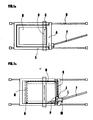
- the apparatus which is the subject of the present invention consists of two coplanar frames, one inside and the other outside, the latter being open on a side perpendicular to the direction of movement, the two frames being guided by slides. parallel.
- the interior frame carries a frosted or opalescent window lit from below by a light source.
- a transparent glass or plastic plate or a film integral with the structure of the device are fixed to the frosted glass.
- This plate or film bears engraved, perpendicular to the direction of movement, a thin reference line.
- the inner frame can be moved by hand in either direction.
- the outer frame located in the same plane as the inner frame, has an open side and therefore, seen in plan, it has a U-shape. This outer frame moves in the same direction as the inner frame from which it borrows movement.
- the movement of the external chassis is regulated by a bar or rod articulated at one of its ends on the frame of the device.
- This bar can therefore take various inclinations with respect to the slides which guide the chassis.
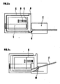
- On this orientable bar is mounted a slide which, by means of an articulated joint, can be made integral with another slide mounted on a rod perpendicular to the direction of movement and integral with the interior frame.
- the inner chassis carries, at its lower part, at its four corners, four idler pulleys mounted idly on ball bearings. On these same pulleys passes a steel belt tensioned by a ten ad hoc. With a clamp, it is possible to link the aforesaid belt to the slide mounted on the orthogonal axis and by means of another clamp, one can also link this belt to the external frame. In this way, a kinematic system has been produced such that by moving the inner chassis in one direction, the outer chassis will follow it in the same direction.
- the displacement of the external chassis will always be equal to that of the internal chassis; there will therefore be no relative displacement of one of the chassis relative to the other, while increasing the angle of inclination of the articulated bar, there will be an increasingly greater relative displacement.
- a support is mounted to which it is possible to fix a pencil or a ball or fiber marker.
- the concentric circles at unit distance drawn on the flat sheet will have undergone all the deformations which, by the survey, can be transformed into a deformation curve.
- the cut box sector is fixed above the polyester film which is integral with the interior frame with the line corresponding to the diameter of the bottom of the box in perfect coincidence with the reference line.
- the articulated bar will have taken a determined inclination and in this displacement, the style will have traced the first coordinate.
- the reference letter (A) designates the interior frame
- the letter (B) the corresponding frosted glass which is lit from below
- the letter (C) indicates the reference line drawn on the transparent plate marked with the letter (D).
- the letter (E) indicates the external frame
- the letter (F) indicates the hinged bar at point (G) of the fixed structure, bar to which one can give, by maneuvering by hand, various inclinations which have the effect of varying the relative displacements of the outer chassis relative to the inner chassis
- the letter (H) indicates the slides which guide the longitudinal displacements.
- Fig. 1b shows the kinematic system which ensures the relative movement of the two chassis relative to each other and the device with two slides which actuates and adjusts this relative movement as a function of the inclination given to the articulated bar.
- the letter (K) designates the orthogonal bar on which the slide (I) moves, linked to the slide (L) which slides on the tilting bar (F).
- the letter (M) designates the style clip which is integral with the slide (L).
- the letter (N) designates the kinematic transmission belt stretched over the four pulleys (O).
- the letter (P) designates the clamp that secures the belt (N) with the outer frame (E).
- the letter (E) designates the outer frame
- the letter (A) the inner frame the letter (C) the reference line
- the letter (S) designates the already stamped box sector which is fixed on the inner frame
- the letter (T) designates the transparent millimeter film which is fixed to the outer frame.
- the letter (V) indicates the plot style and the letter (Z) the small sheet of drawing paper.
- the present invention may obviously also take in its practical embodiment a form different from that which has been illustrated above, but all fall within the same principle of the invention.
- We can, in particular, change the respective positions of the chassis and the rear bar. ticulate, as well as the kinematic transmission system; in addition, all the details of the construction may be replaced by equivalent elements as they may appear obvious to a specialist in this field, without departing from the protective framework of the present invention.
Landscapes
- Engineering & Computer Science (AREA)
- Quality & Reliability (AREA)
- Printing Methods (AREA)
- Electronic Switches (AREA)
- Shaping Metal By Deep-Drawing, Or The Like (AREA)
- Auxiliary Devices For And Details Of Packaging Control (AREA)
Applications Claiming Priority (2)
| Application Number | Priority Date | Filing Date | Title |
|---|---|---|---|
| IT8559285 | 1985-09-09 | ||
| IT85592/85A IT1202121B (it) | 1985-09-09 | 1985-09-09 | Apparecchio meccanico per il rilievo delle deformazioni dell'immagine risultanti nella stampa a colori di scatole metalliche imbutite e per il tracciamento delle relative curve di correzione |
Publications (3)
| Publication Number | Publication Date |
|---|---|
| EP0215718A2 true EP0215718A2 (de) | 1987-03-25 |
| EP0215718A3 EP0215718A3 (en) | 1988-01-20 |
| EP0215718B1 EP0215718B1 (de) | 1991-03-20 |
Family
ID=11328620
Family Applications (1)
| Application Number | Title | Priority Date | Filing Date |
|---|---|---|---|
| EP86420185A Expired - Lifetime EP0215718B1 (de) | 1985-09-09 | 1986-07-08 | Mechanische Vorrichtung zur Ermittlung der beim Mehrfarbdruck von gepressten Metalldosen auftretenden Bildverzerrungen sowie zur Aufzeichnung der entsprechenden Korrekturkurven |
Country Status (10)
| Country | Link |
|---|---|
| EP (1) | EP0215718B1 (de) |
| JP (1) | JPS62122799A (de) |
| DE (1) | DE3678233D1 (de) |
| DK (1) | DK425086D0 (de) |
| ES (1) | ES2001667A6 (de) |
| GR (1) | GR862264B (de) |
| IT (1) | IT1202121B (de) |
| MA (1) | MA20762A1 (de) |
| NO (1) | NO863587L (de) |
| PT (1) | PT83326B (de) |
Cited By (1)
| Publication number | Priority date | Publication date | Assignee | Title |
|---|---|---|---|---|
| US4956906A (en) * | 1988-12-01 | 1990-09-18 | Cebal | Method of preparing pre-distorted images for decorating a shaped blank |
Family Cites Families (2)
| Publication number | Priority date | Publication date | Assignee | Title |
|---|---|---|---|---|
| US2296752A (en) * | 1941-06-11 | 1942-09-22 | William P York | Process of manufacturing embossed articles |
| FR1590126A (de) * | 1968-07-12 | 1970-04-13 |
-
1985
- 1985-09-09 IT IT85592/85A patent/IT1202121B/it active
-
1986
- 1986-07-08 EP EP86420185A patent/EP0215718B1/de not_active Expired - Lifetime
- 1986-07-08 DE DE8686420185T patent/DE3678233D1/de not_active Expired - Lifetime
- 1986-09-02 MA MA20990A patent/MA20762A1/fr unknown
- 1986-09-04 GR GR862264A patent/GR862264B/el unknown
- 1986-09-05 ES ES8601693A patent/ES2001667A6/es not_active Expired
- 1986-09-05 DK DK4250/86A patent/DK425086D0/da not_active Application Discontinuation
- 1986-09-08 NO NO863587A patent/NO863587L/no unknown
- 1986-09-08 PT PT83326A patent/PT83326B/pt not_active IP Right Cessation
- 1986-09-09 JP JP61212545A patent/JPS62122799A/ja active Pending
Cited By (2)
| Publication number | Priority date | Publication date | Assignee | Title |
|---|---|---|---|---|
| US4956906A (en) * | 1988-12-01 | 1990-09-18 | Cebal | Method of preparing pre-distorted images for decorating a shaped blank |
| US5143793A (en) * | 1988-12-01 | 1992-09-01 | Cebal | Decorated hollow element |
Also Published As
| Publication number | Publication date |
|---|---|
| MA20762A1 (fr) | 1987-04-01 |
| JPS62122799A (ja) | 1987-06-04 |
| GR862264B (en) | 1986-11-18 |
| DE3678233D1 (de) | 1991-04-25 |
| IT1202121B (it) | 1989-02-02 |
| PT83326B (pt) | 1993-01-29 |
| NO863587D0 (no) | 1986-09-08 |
| EP0215718A3 (en) | 1988-01-20 |
| PT83326A (pt) | 1986-10-01 |
| DK425086D0 (da) | 1986-09-05 |
| ES2001667A6 (es) | 1988-06-01 |
| NO863587L (no) | 1987-03-10 |
| IT8585592A0 (it) | 1985-09-09 |
| EP0215718B1 (de) | 1991-03-20 |
Similar Documents
| Publication | Publication Date | Title |
|---|---|---|
| EP0156747B1 (de) | Verfahren und Vorrichtung zum Ausschneiden von quadratischen oder rechteckigen Öffnungen in Bilderrahmen | |
| CA2004193C (fr) | Procede de decoration d'une ebauche a conformer, utilisation de ce procede et produits obtenus | |
| EP0532257A3 (de) | Apparat zum Bestimmen der Schweissnahtgüte | |
| FR2733709A1 (fr) | Ameliorations concernant le calibrage du diametre de parties cylindriques excentrees de pieces a usiner | |
| CH621882A5 (de) | ||
| WO2015001255A1 (fr) | Systeme d'inspection d'un objet au moins translucide creux presentant au moins un marquage | |
| EP0215718B1 (de) | Mechanische Vorrichtung zur Ermittlung der beim Mehrfarbdruck von gepressten Metalldosen auftretenden Bildverzerrungen sowie zur Aufzeichnung der entsprechenden Korrekturkurven | |
| US4253763A (en) | Reprographic camera | |
| WO2000000924A1 (fr) | Procede et dispositif de lecture de reliefs portes par un recipient transparent ou translucide | |
| NO123011B (de) | ||
| CA2212941A1 (fr) | Procede de controle d'un recipient en verre | |
| FR2460180A1 (fr) | Dispositif indicateur de cote destine a equiper une machine-outil de formage ou de cisaillage de metaux en feuilles | |
| FR2529487A1 (fr) | Procede et installation pour le traitement de toles brutes issues d'un laminoir a produits plats | |
| EP0203014B1 (de) | Photomechanisches Kontaktgerät zur Korrektion der Bilddeformation beim Extrudierprozess von Metallbüchsen | |
| EP0677720B1 (de) | Vorrichtung zur Profilmessung einer ebenen Oberfläche | |
| FR2483269A1 (fr) | Ouvreur de bobine | |
| FR2464495A1 (fr) | Filtre spatial directionnel a coupure haute pour appareil d'inspection de defauts | |
| US2080172A (en) | Reading machine | |
| FR2554610A1 (fr) | Procede d'anamorphose d'illustration d'emballage cylindrique embouti pour l'impression sur le flan avant emboutissage, et appareil mettant en oeuvre ce procede | |
| EP0094309B1 (de) | Vorrichtung zur gleichzeitigen Steuerung mehrerer Ritzgeräte zum parallel in Längsrichtung Ritzen eines sich bewegenden Glasbandes | |
| EP0220994B1 (de) | Kontaktkopiergerät zur Herstellung von kreisförmigen Kopien aus normalen photographischen Originalen | |
| EP0124553A1 (de) | Verbesserung an optischen einrichtungen zum aufdrucken auf seitenwänden von behältern die durch ausstanzen hergestellt werden. | |
| EP0311534A1 (de) | Kopiermaschine für Schleifmaschine drehender Schleifscheibe und dazugehörige Schleifmaschine | |
| FR2637540A1 (en) | Device making it possible to draw ellipses | |
| CH106581A (fr) | Dispositif de mise au point pour appareil de projection optique. |
Legal Events
| Date | Code | Title | Description |
|---|---|---|---|
| PUAI | Public reference made under article 153(3) epc to a published international application that has entered the european phase |
Free format text: ORIGINAL CODE: 0009012 |
|
| AK | Designated contracting states |
Kind code of ref document: A2 Designated state(s): BE DE FR GB IT LU NL SE |
|
| PUAL | Search report despatched |
Free format text: ORIGINAL CODE: 0009013 |
|
| AK | Designated contracting states |
Kind code of ref document: A3 Designated state(s): BE DE FR GB IT LU NL SE |
|
| 17P | Request for examination filed |
Effective date: 19880604 |
|
| 17Q | First examination report despatched |
Effective date: 19891016 |
|
| GRAA | (expected) grant |
Free format text: ORIGINAL CODE: 0009210 |
|
| AK | Designated contracting states |
Kind code of ref document: B1 Designated state(s): BE DE FR GB IT LU NL SE |
|
| ITF | It: translation for a ep patent filed | ||
| GBT | Gb: translation of ep patent filed (gb section 77(6)(a)/1977) | ||
| REF | Corresponds to: |
Ref document number: 3678233 Country of ref document: DE Date of ref document: 19910425 |
|
| PLBE | No opposition filed within time limit |
Free format text: ORIGINAL CODE: 0009261 |
|
| STAA | Information on the status of an ep patent application or granted ep patent |
Free format text: STATUS: NO OPPOSITION FILED WITHIN TIME LIMIT |
|
| 26N | No opposition filed | ||
| PGFP | Annual fee paid to national office [announced via postgrant information from national office to epo] |
Ref country code: DE Payment date: 19920615 Year of fee payment: 7 |
|
| PGFP | Annual fee paid to national office [announced via postgrant information from national office to epo] |
Ref country code: SE Payment date: 19920618 Year of fee payment: 7 |
|
| PGFP | Annual fee paid to national office [announced via postgrant information from national office to epo] |
Ref country code: GB Payment date: 19920622 Year of fee payment: 7 |
|
| PGFP | Annual fee paid to national office [announced via postgrant information from national office to epo] |
Ref country code: LU Payment date: 19920629 Year of fee payment: 7 |
|
| PGFP | Annual fee paid to national office [announced via postgrant information from national office to epo] |
Ref country code: FR Payment date: 19920715 Year of fee payment: 7 |
|
| PGFP | Annual fee paid to national office [announced via postgrant information from national office to epo] |
Ref country code: BE Payment date: 19920731 Year of fee payment: 7 Ref country code: NL Payment date: 19920731 Year of fee payment: 7 |
|
| EPTA | Lu: last paid annual fee | ||
| PG25 | Lapsed in a contracting state [announced via postgrant information from national office to epo] |
Ref country code: LU Free format text: LAPSE BECAUSE OF NON-PAYMENT OF DUE FEES Effective date: 19930708 Ref country code: GB Effective date: 19930708 |
|
| PG25 | Lapsed in a contracting state [announced via postgrant information from national office to epo] |
Ref country code: SE Effective date: 19930709 |
|
| PG25 | Lapsed in a contracting state [announced via postgrant information from national office to epo] |
Ref country code: BE Effective date: 19930731 |
|
| BERE | Be: lapsed |
Owner name: PACCAGNELLA GIUSEPPE Effective date: 19930731 |
|
| PG25 | Lapsed in a contracting state [announced via postgrant information from national office to epo] |
Ref country code: NL Effective date: 19940201 |
|
| GBPC | Gb: european patent ceased through non-payment of renewal fee |
Effective date: 19930708 |
|
| NLV4 | Nl: lapsed or anulled due to non-payment of the annual fee | ||
| PG25 | Lapsed in a contracting state [announced via postgrant information from national office to epo] |
Ref country code: FR Effective date: 19940331 |
|
| PG25 | Lapsed in a contracting state [announced via postgrant information from national office to epo] |
Ref country code: DE Effective date: 19940401 |
|
| REG | Reference to a national code |
Ref country code: FR Ref legal event code: ST |
|
| EUG | Se: european patent has lapsed |
Ref document number: 86420185.0 Effective date: 19940210 |
|
| PG25 | Lapsed in a contracting state [announced via postgrant information from national office to epo] |
Ref country code: IT Free format text: LAPSE BECAUSE OF NON-PAYMENT OF DUE FEES;WARNING: LAPSES OF ITALIAN PATENTS WITH EFFECTIVE DATE BEFORE 2007 MAY HAVE OCCURRED AT ANY TIME BEFORE 2007. THE CORRECT EFFECTIVE DATE MAY BE DIFFERENT FROM THE ONE RECORDED. Effective date: 20050708 |