EP0215674B1 - Self-aligning optical fiber and fiber-ring optical resonator using same - Google Patents
Self-aligning optical fiber and fiber-ring optical resonator using same Download PDFInfo
- Publication number
- EP0215674B1 EP0215674B1 EP86307146A EP86307146A EP0215674B1 EP 0215674 B1 EP0215674 B1 EP 0215674B1 EP 86307146 A EP86307146 A EP 86307146A EP 86307146 A EP86307146 A EP 86307146A EP 0215674 B1 EP0215674 B1 EP 0215674B1
- Authority
- EP
- European Patent Office
- Prior art keywords
- fiber
- fibers
- portions
- flat surface
- core
- Prior art date
- Legal status (The legal status is an assumption and is not a legal conclusion. Google has not performed a legal analysis and makes no representation as to the accuracy of the status listed.)
- Expired - Lifetime
Links
- 239000013307 optical fiber Substances 0.000 title claims description 65
- 230000003287 optical effect Effects 0.000 title description 16
- 239000000835 fiber Substances 0.000 claims description 164
- 238000005253 cladding Methods 0.000 claims description 31
- 230000010287 polarization Effects 0.000 claims description 19
- 238000010168 coupling process Methods 0.000 claims description 15
- 238000005859 coupling reaction Methods 0.000 claims description 15
- 238000000034 method Methods 0.000 claims description 15
- 230000008878 coupling Effects 0.000 claims description 14
- 239000000758 substrate Substances 0.000 claims description 12
- 239000011521 glass Substances 0.000 claims description 9
- 230000005684 electric field Effects 0.000 claims description 8
- 238000005530 etching Methods 0.000 claims description 6
- 230000005484 gravity Effects 0.000 claims description 6
- 238000010438 heat treatment Methods 0.000 claims description 5
- 230000000644 propagated effect Effects 0.000 claims description 5
- 230000003993 interaction Effects 0.000 claims description 2
- 230000000295 complement effect Effects 0.000 claims 4
- 230000001427 coherent effect Effects 0.000 claims 1
- 238000001816 cooling Methods 0.000 claims 1
- 238000007493 shaping process Methods 0.000 claims 1
- 230000008901 benefit Effects 0.000 description 7
- VYPSYNLAJGMNEJ-UHFFFAOYSA-N silicon dioxide Inorganic materials O=[Si]=O VYPSYNLAJGMNEJ-UHFFFAOYSA-N 0.000 description 7
- 230000006698 induction Effects 0.000 description 5
- 238000004519 manufacturing process Methods 0.000 description 5
- OKTJSMMVPCPJKN-UHFFFAOYSA-N Carbon Chemical compound [C] OKTJSMMVPCPJKN-UHFFFAOYSA-N 0.000 description 4
- 229910002804 graphite Inorganic materials 0.000 description 4
- 239000010439 graphite Substances 0.000 description 4
- 230000008569 process Effects 0.000 description 4
- 238000005388 cross polarization Methods 0.000 description 3
- 230000007246 mechanism Effects 0.000 description 3
- 239000000377 silicon dioxide Substances 0.000 description 3
- XKRFYHLGVUSROY-UHFFFAOYSA-N Argon Chemical compound [Ar] XKRFYHLGVUSROY-UHFFFAOYSA-N 0.000 description 2
- KRHYYFGTRYWZRS-UHFFFAOYSA-N Fluorane Chemical compound F KRHYYFGTRYWZRS-UHFFFAOYSA-N 0.000 description 2
- 230000008859 change Effects 0.000 description 2
- 238000011161 development Methods 0.000 description 2
- 230000010363 phase shift Effects 0.000 description 2
- 230000001902 propagating effect Effects 0.000 description 2
- 238000012546 transfer Methods 0.000 description 2
- VXEGSRKPIUDPQT-UHFFFAOYSA-N 4-[4-(4-methoxyphenyl)piperazin-1-yl]aniline Chemical group C1=CC(OC)=CC=C1N1CCN(C=2C=CC(N)=CC=2)CC1 VXEGSRKPIUDPQT-UHFFFAOYSA-N 0.000 description 1
- 230000001133 acceleration Effects 0.000 description 1
- 229910052786 argon Inorganic materials 0.000 description 1
- 230000005540 biological transmission Effects 0.000 description 1
- 238000007796 conventional method Methods 0.000 description 1
- 239000007822 coupling agent Substances 0.000 description 1
- 238000000151 deposition Methods 0.000 description 1
- 238000009792 diffusion process Methods 0.000 description 1
- 239000012153 distilled water Substances 0.000 description 1
- 238000009826 distribution Methods 0.000 description 1
- 230000000694 effects Effects 0.000 description 1
- 230000005672 electromagnetic field Effects 0.000 description 1
- 230000007613 environmental effect Effects 0.000 description 1
- 238000002839 fiber optic waveguide Methods 0.000 description 1
- 229920002457 flexible plastic Polymers 0.000 description 1
- YBMRDBCBODYGJE-UHFFFAOYSA-N germanium dioxide Chemical group O=[Ge]=O YBMRDBCBODYGJE-UHFFFAOYSA-N 0.000 description 1
- 238000000227 grinding Methods 0.000 description 1
- 239000011261 inert gas Substances 0.000 description 1
- QSHDDOUJBYECFT-UHFFFAOYSA-N mercury Chemical compound [Hg] QSHDDOUJBYECFT-UHFFFAOYSA-N 0.000 description 1
- 229910052753 mercury Inorganic materials 0.000 description 1
- 238000012986 modification Methods 0.000 description 1
- 230000004048 modification Effects 0.000 description 1
- 238000002360 preparation method Methods 0.000 description 1
- 238000004321 preservation Methods 0.000 description 1
- 230000000284 resting effect Effects 0.000 description 1
- 230000000717 retained effect Effects 0.000 description 1
- 235000012239 silicon dioxide Nutrition 0.000 description 1
- 239000005049 silicon tetrachloride Substances 0.000 description 1
- 239000007787 solid Substances 0.000 description 1
- 238000001228 spectrum Methods 0.000 description 1
- IEXRMSFAVATTJX-UHFFFAOYSA-N tetrachlorogermane Chemical compound Cl[Ge](Cl)(Cl)Cl IEXRMSFAVATTJX-UHFFFAOYSA-N 0.000 description 1
- 238000005979 thermal decomposition reaction Methods 0.000 description 1
- 239000013306 transparent fiber Substances 0.000 description 1
- XLYOFNOQVPJJNP-UHFFFAOYSA-N water Chemical compound O XLYOFNOQVPJJNP-UHFFFAOYSA-N 0.000 description 1
Images

Classifications
-
- C—CHEMISTRY; METALLURGY
- C03—GLASS; MINERAL OR SLAG WOOL
- C03B—MANUFACTURE, SHAPING, OR SUPPLEMENTARY PROCESSES
- C03B37/00—Manufacture or treatment of flakes, fibres, or filaments from softened glass, minerals, or slags
- C03B37/01—Manufacture of glass fibres or filaments
- C03B37/02—Manufacture of glass fibres or filaments by drawing or extruding, e.g. direct drawing of molten glass from nozzles; Cooling fins therefor
- C03B37/025—Manufacture of glass fibres or filaments by drawing or extruding, e.g. direct drawing of molten glass from nozzles; Cooling fins therefor from reheated softened tubes, rods, fibres or filaments, e.g. drawing fibres from preforms
- C03B37/027—Fibres composed of different sorts of glass, e.g. glass optical fibres
- C03B37/02709—Polarisation maintaining fibres, e.g. PM, PANDA, bi-refringent optical fibres
-
- C—CHEMISTRY; METALLURGY
- C03—GLASS; MINERAL OR SLAG WOOL
- C03B—MANUFACTURE, SHAPING, OR SUPPLEMENTARY PROCESSES
- C03B37/00—Manufacture or treatment of flakes, fibres, or filaments from softened glass, minerals, or slags
- C03B37/01—Manufacture of glass fibres or filaments
- C03B37/012—Manufacture of preforms for drawing fibres or filaments
- C03B37/01205—Manufacture of preforms for drawing fibres or filaments starting from tubes, rods, fibres or filaments
-
- C—CHEMISTRY; METALLURGY
- C03—GLASS; MINERAL OR SLAG WOOL
- C03B—MANUFACTURE, SHAPING, OR SUPPLEMENTARY PROCESSES
- C03B37/00—Manufacture or treatment of flakes, fibres, or filaments from softened glass, minerals, or slags
- C03B37/01—Manufacture of glass fibres or filaments
- C03B37/02—Manufacture of glass fibres or filaments by drawing or extruding, e.g. direct drawing of molten glass from nozzles; Cooling fins therefor
- C03B37/025—Manufacture of glass fibres or filaments by drawing or extruding, e.g. direct drawing of molten glass from nozzles; Cooling fins therefor from reheated softened tubes, rods, fibres or filaments, e.g. drawing fibres from preforms
- C03B37/029—Furnaces therefor
-
- C—CHEMISTRY; METALLURGY
- C03—GLASS; MINERAL OR SLAG WOOL
- C03B—MANUFACTURE, SHAPING, OR SUPPLEMENTARY PROCESSES
- C03B37/00—Manufacture or treatment of flakes, fibres, or filaments from softened glass, minerals, or slags
- C03B37/10—Non-chemical treatment
- C03B37/14—Re-forming fibres or filaments, i.e. changing their shape
-
- G—PHYSICS
- G02—OPTICS
- G02B—OPTICAL ELEMENTS, SYSTEMS OR APPARATUS
- G02B6/00—Light guides; Structural details of arrangements comprising light guides and other optical elements, e.g. couplings
- G02B6/10—Light guides; Structural details of arrangements comprising light guides and other optical elements, e.g. couplings of the optical waveguide type
- G02B6/105—Light guides; Structural details of arrangements comprising light guides and other optical elements, e.g. couplings of the optical waveguide type having optical polarisation effects
-
- G—PHYSICS
- G02—OPTICS
- G02B—OPTICAL ELEMENTS, SYSTEMS OR APPARATUS
- G02B6/00—Light guides; Structural details of arrangements comprising light guides and other optical elements, e.g. couplings
- G02B6/24—Coupling light guides
- G02B6/26—Optical coupling means
- G02B6/28—Optical coupling means having data bus means, i.e. plural waveguides interconnected and providing an inherently bidirectional system by mixing and splitting signals
- G02B6/2804—Optical coupling means having data bus means, i.e. plural waveguides interconnected and providing an inherently bidirectional system by mixing and splitting signals forming multipart couplers without wavelength selective elements, e.g. "T" couplers, star couplers
- G02B6/2821—Optical coupling means having data bus means, i.e. plural waveguides interconnected and providing an inherently bidirectional system by mixing and splitting signals forming multipart couplers without wavelength selective elements, e.g. "T" couplers, star couplers using lateral coupling between contiguous fibres to split or combine optical signals
- G02B6/2835—Optical coupling means having data bus means, i.e. plural waveguides interconnected and providing an inherently bidirectional system by mixing and splitting signals forming multipart couplers without wavelength selective elements, e.g. "T" couplers, star couplers using lateral coupling between contiguous fibres to split or combine optical signals formed or shaped by thermal treatment, e.g. couplers
-
- G—PHYSICS
- G02—OPTICS
- G02B—OPTICAL ELEMENTS, SYSTEMS OR APPARATUS
- G02B6/00—Light guides; Structural details of arrangements comprising light guides and other optical elements, e.g. couplings
- G02B6/24—Coupling light guides
- G02B6/26—Optical coupling means
- G02B6/28—Optical coupling means having data bus means, i.e. plural waveguides interconnected and providing an inherently bidirectional system by mixing and splitting signals
- G02B6/2804—Optical coupling means having data bus means, i.e. plural waveguides interconnected and providing an inherently bidirectional system by mixing and splitting signals forming multipart couplers without wavelength selective elements, e.g. "T" couplers, star couplers
- G02B6/2821—Optical coupling means having data bus means, i.e. plural waveguides interconnected and providing an inherently bidirectional system by mixing and splitting signals forming multipart couplers without wavelength selective elements, e.g. "T" couplers, star couplers using lateral coupling between contiguous fibres to split or combine optical signals
- G02B6/2843—Optical coupling means having data bus means, i.e. plural waveguides interconnected and providing an inherently bidirectional system by mixing and splitting signals forming multipart couplers without wavelength selective elements, e.g. "T" couplers, star couplers using lateral coupling between contiguous fibres to split or combine optical signals the couplers having polarisation maintaining or holding properties
-
- G—PHYSICS
- G02—OPTICS
- G02B—OPTICAL ELEMENTS, SYSTEMS OR APPARATUS
- G02B6/00—Light guides; Structural details of arrangements comprising light guides and other optical elements, e.g. couplings
- G02B6/24—Coupling light guides
- G02B6/36—Mechanical coupling means
- G02B6/38—Mechanical coupling means having fibre to fibre mating means
- G02B6/3801—Permanent connections, i.e. wherein fibres are kept aligned by mechanical means
- G02B6/3803—Adjustment or alignment devices for alignment prior to splicing
-
- G—PHYSICS
- G02—OPTICS
- G02B—OPTICAL ELEMENTS, SYSTEMS OR APPARATUS
- G02B6/00—Light guides; Structural details of arrangements comprising light guides and other optical elements, e.g. couplings
- G02B6/24—Coupling light guides
- G02B6/42—Coupling light guides with opto-electronic elements
- G02B6/4201—Packages, e.g. shape, construction, internal or external details
- G02B6/4216—Packages, e.g. shape, construction, internal or external details incorporating polarisation-maintaining fibres
-
- C—CHEMISTRY; METALLURGY
- C03—GLASS; MINERAL OR SLAG WOOL
- C03B—MANUFACTURE, SHAPING, OR SUPPLEMENTARY PROCESSES
- C03B2203/00—Fibre product details, e.g. structure, shape
- C03B2203/02—External structure or shape details
-
- C—CHEMISTRY; METALLURGY
- C03—GLASS; MINERAL OR SLAG WOOL
- C03B—MANUFACTURE, SHAPING, OR SUPPLEMENTARY PROCESSES
- C03B2203/00—Fibre product details, e.g. structure, shape
- C03B2203/02—External structure or shape details
- C03B2203/04—Polygonal outer cross-section, e.g. triangular, square
-
- C—CHEMISTRY; METALLURGY
- C03—GLASS; MINERAL OR SLAG WOOL
- C03B—MANUFACTURE, SHAPING, OR SUPPLEMENTARY PROCESSES
- C03B2203/00—Fibre product details, e.g. structure, shape
- C03B2203/10—Internal structure or shape details
-
- C—CHEMISTRY; METALLURGY
- C03—GLASS; MINERAL OR SLAG WOOL
- C03B—MANUFACTURE, SHAPING, OR SUPPLEMENTARY PROCESSES
- C03B2203/00—Fibre product details, e.g. structure, shape
- C03B2203/30—Polarisation maintaining [PM], i.e. birefringent products, e.g. with elliptical core, by use of stress rods, "PANDA" type fibres
-
- C—CHEMISTRY; METALLURGY
- C03—GLASS; MINERAL OR SLAG WOOL
- C03B—MANUFACTURE, SHAPING, OR SUPPLEMENTARY PROCESSES
- C03B2203/00—Fibre product details, e.g. structure, shape
- C03B2203/32—Eccentric core or cladding
-
- C—CHEMISTRY; METALLURGY
- C03—GLASS; MINERAL OR SLAG WOOL
- C03B—MANUFACTURE, SHAPING, OR SUPPLEMENTARY PROCESSES
- C03B2203/00—Fibre product details, e.g. structure, shape
- C03B2203/34—Plural core other than bundles, e.g. double core
-
- C—CHEMISTRY; METALLURGY
- C03—GLASS; MINERAL OR SLAG WOOL
- C03B—MANUFACTURE, SHAPING, OR SUPPLEMENTARY PROCESSES
- C03B2205/00—Fibre drawing or extruding details
- C03B2205/60—Optical fibre draw furnaces
- C03B2205/62—Heating means for drawing
- C03B2205/64—Induction furnaces, i.e. HF/RF coil, e.g. of the graphite or zirconia susceptor type
Definitions
- the present invention relates generally to the field of fiber optics, and particularly single-moded and dual-polarization-preserving fiber-optic waveguides.
- Fiber optics is generally concerned with the transmission of light along a transparent fiber structure which has a higher refractive index than its surroundings.
- single-mode sensors use amplitude variations in the optical signals to sense and transmit the desired information
- single-mode sensors use phase variations rather than amplitude variations.
- the single-mode sensors usually involve mechanisms for altering such properties of the fiber as path length or index of refraction to effect the desired phase variations in the optical signal.
- the single-mode sensor measures acceleration which inherently alters the propagation of light even though the fiber is not affected.
- the uniformity and mechanism of light propagation and hence the characteristics of the fiber are especially critical.
- Single-mode sensors and fiber components such as directional couplers, are sensitive to the state of polarization of the light in the fiber.
- polarization-holding fibers are capable of preserving the polarization of signals along two different, usually orthogonal, axes, such as the major and minor axes of an elliptical core.
- multiple core and cladding layers may be deposited on the inside of a preform which is then collapsed and drawn, so that the preform tube becomes a support jacket around the core and cladding layers.
- Light propagated through a fiber formed in this manner is confined to the guiding region formed by the core and cladding layers and does not significantly interact with the support jacket. Consequently the optical properties of the support jacket can be considerably inferior to the optical qualities of the core and cladding.
- elliptical-core, polarization-preserving optical fibers may be drawn from elliptical-core preforms.
- the preforms may be manufactured by collapsing a cylindrical preform or tube, with a slight vacuum in the center.
- Another method of manufacturing an elliptical-core preform is to fabricate the substrate tube to have a wall of non-uniform thickness and then collapse the tube by heating it to the softening point. The surface tension in the shaped wall, which occurs during the collapsing and subsequent drawing steps, causes the resulting fiber core to be elliptical in cross-section. See, e.g., Pleibel et al. U.S. Patent 4,274,854 issued June 23, 1981.
- fibers with elliptical cores and a large index difference between the core and cladding preserve the polarization of fundamental modes aligned with the long and short axes of the ellipse, i.e., modes having their electric fields parallel to the major and minor axes of the ellipse. If the core-cladding index difference and the difference between the lengths of the major and minor axes of the ellipse are sufficiently large to avoid coupling of the two fundamental modes, the polarization of both modes is preserved.
- a related object of the invention is to provide such an improved optical fiber which permits accurate splicing with extremely low losses across the splices.
- a related object of the invention is to provide such couplers which are capable of coupling signals to and from either or both of the transverse axes of two or more fibers in a single coupler.
- an optical fiber comprising a core and cladding having different refractive indices and forming a single-mode guiding region, the outer longitudinal surface of the fiber having a pair of orthogonal exterior flat longitudinal surface-portions so that the location of the guiding region can be ascertained from the geometry of the exterior surfaces of the fiber, and the guiding region being offset from the center of gravity of the transverse cross-section of the fiber and located sufficiently close to at least one of said flat surfaces to allow coupling to a guided wave through that surface.
- the core also has a non-circular cross-section defining two transverse orthogonal axes, the core having a longer transverse dimension along one of the orthogonal axes than along the other of the axes for guiding two fundamental modes, one of the fundamental modes having an electric field parallel to the axis of the longer transverse dimension and the other of the fundamental modes having an electric field parallel to the axis of the shorter transverse dimension; the difference in the core dimensions along the orthogonal transverse axes and the difference between the refractive indices of the core and cladding are sufficiently large to decouple the fundamental modes so that the polarization of the two modes is preserved within the fiber; the guiding region is offset from the geometric center of the fiber and located sufficiently close to one side of the surface of the fiber to allow coupling to a guided wave through that one side; and the outer surface of the fiber has a non-circular cross-section forming an indexing surface with a predetermined geometric relationship to the guiding region and the orthogonal transverse
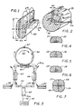
- FIG. 1 there is shown a dielectric core 20 for supporting the propagation of electromagnetic fields E, H in the axial direction.
- This particular core 20 has an elliptical cross-section with a major diameter 2 a and a minor diameter 2 b , i.e. a and b are the radii of the core at the major and minor axes, respectively.
- a and b are the radii of the core at the major and minor axes, respectively.
- such a core 20 has a relatively high dielectric constant/index of refraction which tends to confine and guide electromagnetic energy (i.e., light) along the axis of the core.
- the index of refraction of the core 20 is properly chosen in relation to the index of refraction of the surrounding medium, the core dimensions a , b , and the wavelength of the light, the distribution of the fields E, H will tend to occur in a single, well-defined pattern, or mode. Shown in FIG. 1 is the field pattern for the o HE11 mode (part of elliptical core 20 being cut away to facilitate pictorial representation of the field pattern along the length of the core).
- Single-mode propagation has the advantage of providing well-defined field patterns for coupling the fiber to optical devices. Another advantage is that the attributes of the light propagation, such as phase velocity and group velocity, are relatively constant as the light propagates down the fiber.
- the group velocity specifies how fast modulation or information travels down the fiber. Thus, for transmitting information over long distances it is important that the group velocity be relatively constant and in particular independent of frequency so that the information will be localized at a specific region rather than becoming "smeared out” as the information travels down the fiber.
- a single constant phase velocity is important in fiber-optic sensor applications where the phase of a signal in a sensor fiber is compared to the phase of a reference signal in a reference fiber.
- Polarization is defined as the direction of the electric field vector E.
- the light is polarized in a vertical direction.
- the phase of the optical signal at the end of a sensor fiber is made a function of an environmental parameter sought to be measured.
- this phase-shift is introduced by physically lengthening the fiber, or by changing the index of refraction of the core 20.
- the waveguide is not polarization-preserving, the polarization of the light tends to change randomly as the light propagates down the axis of the core 20.
- Such a random change in polarization results in a fluctuation of the detected signal since a 180° rotation of the direction of polarization is equivalent, at the end of the fiber, to a 180° phase shift.
- the polarization of the light should be maintained at a fixed angular relationship with respect to the fiber as the light propagates down the core.
- the optical properties of the fiber must be anisotropic, or in other words a function of the angle of polarization with respect to the fiber.
- One method of making the optical fiber anisotropic is to make the core 20 have a cross-section which is elliptical or some other non-circular shape which defines two transverse orthogonal axes permitting the de-coupling of waves polarized along those axes. Signals which are launched into such fibers in alignment with one of the transverse axes tend to remain aligned with that axis as the signals are propagated through the fiber, thereby preserving the polarization of the signal.
- an optical fiber 25 has an elliptical core 26 with a relatively high index of refraction surrounded by a cladding 27 with a lower index of refraction to produce a high difference in index (e.g., a ⁇ n of 0.06).
- the dimensions and the refractive indices of the core 26 and the cladding 27 are selected to provide a single-mode guiding region. Because of its elliptical shape and high index difference, this guiding region will also hold the polarization of optical signals propagated therethrough in alignment with either axis of the ellipse.
- the major and minor axes of the elliptical cross-section represent two transverse orthogonal axes which, in combination with the refractive indices of the core and cladding, de-couple light waves polarized along those axes.
- a support layer 28 Surrounding the guiding region formed by the core 26 and cladding 27 is a support layer 28 which provides the fiber with increased mechanical strength and ease of manipulation. Since this support layer 28 is not a part of the guiding region, its optical properties are not nearly as critical as those of the core 26 and the cladding 27. To prevent light from being trapped in the cladding 27, the support layer 28 has an index of refraction higher than that of the cladding 27.
- an optical fiber with a guiding region having orthogonal polarization-holding axes i.e., axes of birefringence
- an outer surface having a pair of orthogonal flat surface-portions each of which is parallel to one of the polarization-holding axes so that the location of the guiding region and the orientation of the axes of birefringence therein can be ascertained from the geometry of the outer surface of the fiber.
- the outer surface of the support layer 28 forms a first flat surface-portion 29 parallel to the major axis of the elliptical guiding region, and a second flat surface-portion 30 parallel to the minor axis of the elliptical guiding region.
- the flat surface-portion is located sufficiently close to the guiding region that etching away a layer ⁇ a from the outer surface of the fiber exposes the major axis of the elliptical guiding region in the surface-portion 29.
- the other flat surface-portion 30 is spaced farther away from the guiding region, by a distance ⁇ b, so that the minor axis of the elliptical guiding region is not exposed by merely etching away the thickness ⁇ a.
- One of the significant advantages of the fiber of this invention is that it permits precise, low-loss splices to be made. That is, the guiding regions at two similar fiber ends can be aligned with each other by simply placing the two fiber ends on a common substrate 31 having a groove with orthogonal walls 32 and 33, with the orthogonal flat surface-portions on the two fiber ends resting against the orthogonal walls of the substrate.
- the two fiber ends are butted firmly together and joined to each other and to the substrate 31 by a suitable bonding or encapsulating means, preferably with the addition of a coupling agent in the interface between the two abutting surfaces of the fiber ends.
- This improved splice is particularly useful is in the fabrication of a high-performance fiber-ring resonator using a closed fiber ring formed by splicing the ends of a length of this fiber.
- the two ends of the fiber can be spliced with precise alignment of the guiding regions at the two ends of the fiber.
- the splice has negligible loss.
- the closed ring formed by this splice can then be loosely coupled to a fiber carrying the input signal to the ring and the output signal to a detector.
- Such a fiber-ring resonator is illustrated schematically in Fig. 3 where a laser 40 supplies an optical signal S o at a frequency f o through an optical fiber 41 which forms a loop 41a.
- the two ends of this loop 41a are coupled through a 3-dB coupler 42 which splits the signal into two components S1 and S2.
- These two components are propagated in opposite directions through the fiber loop 41a and respective 3-dB couplers 43 and 44, and then on through a 10-dB coupler 45 which provides loose coupling to a sensing ring 46. It is this ring 46 that is formed by the fiber of the present invention, with a low-loss splice 47.
- the portions of the two signals S1 and S2 that are coupled into the ring 46 propagate around the ring in opposite directions, and any rotation of the ring causes a shift ⁇ f in the frequency of both signals, in opposite directions. That is, if the ring is rotated in the direction indicated by the arrow 48, the signal S1 is shifted to a frequency (f o - ⁇ f) , and the signal S2 is shifted to a frequency (f o + ⁇ f) . Fractions of these shifted signals are then coupled back into the fiber loop 41a through the 10-dB coupler 45, and propagate in opposite directions through the loop to the 3-dB couplers 43 and 44.
- the coupler 43 receives the shifted signal S2 propagating in the opposite direction with a frequency (f o + ⁇ f ), and the coupler 44 receives the shifted signal S1 propagating in the opposite direction with a frequency (f o - ⁇ f) .
- These signals are coupled into respective detectors 49 and 50 which convert the optical signals into analogous electrical signals which can be used to measure the magnitude of ⁇ f.
- the electrical signals can be fed to a superheterodyne having a local oscillator frequency of f o .
- one of the two couplers 43 and 44 and its corresponding detector 49 or 50 could be omitted, although the use of both couplers and detectors offers the advantage of doubling the sensed frequency shift.
- FIG. 4 illustrates a pair of fibers 51 and 52 arranged to couple signals polarized along the minor axes of the elliptical cores
- FIG. 5 illustrates another pair of fibers 53 and 54 arranged to couple signals polarized along the major axes of the elliptical cores.
- the coupler of either FIG. 4 or FIG. 5 can be formed from the same pair of fibers.
- FIG. 6 illustrates yet another coupler that can be formed from a similar pair of fibers 55 and 56, this time coupling signals polarized along the major axis of the elliptical core of one fiber 55 and the minor axis of the elliptical core of the fiber 56.
- FIG. 7 illustrates a four-way coupler formed from four fibers 57-60, providing two co-polarization couplings (between fibers 57, 60 and fibers 58, 59) and two cross-polarization couplings (between fibers 57, 58 and fibers 59, 60) within a single, integral coupler.
- the optical fiber of this invention is preferably made by forming a preform having the desired transverse cross-sectional configuration and drawing an optical fiber from the preform, with the drawing rate and temperature being controlled to produce a fiber with a cross-sectional configuration similar to that of the preform.
- the preform can have the same cross-sectional configuration as the fiber 25 illustrated in FIG. 2, though on a larger scale.
- Such a preform can be made by first forming a cylindrical preform with an elliptical core and cladding located in the center thereof (using techniques known in the art), and then grinding two adjacent sides of the preform to form a cross-section having one flat surface parallel to the major axis of the elliptical core and another flat surface parallel to the minor axis of the elliptical core. An optical fiber is then drawn from the ground preform at a drawing rate and temperature controlled to produce the fiber 25 of FIG. 2, i.e., with a cross-sectional geometry substantially the same as that of the preform but on a smaller scale.
- FIG. 8 A drawing machine suitable for precise control of the drawing process is shown in FIG. 8.
- the central component of the drawing machine is an induction furnace generally designated 60 comprising an external induction coil 61 and an internal graphite toroid 62.
- the toroid 62 is approximately 4 inches long, an inch in diameter, and has a core hole about a quarter inch in diameter.
- the induction coil 61 is energized by a radio-frequency power source 63 so that the electrical heating currents are induced in the graphite toroid 62, the resulting temperature being measured by an optical pyrometer 64 and monitored by a control unit 65 adjusting the power source 63.
- the toroid 62 is disposed within a glass cylinder 66 which is filled with a relatively inert gas such as argon from a supply 67.
- a preform 68 is fed into the top of the cylinder 66 and passes through the center of the graphite toroid 62.
- the toroid 62 is heated white hot, causing the preform 68 to soften.
- the drawing of the fiber 69 from the preform 68 occurs approximately at the center of the toroid 62.
- the toroid 62 has legs 71 which stand on a support ring 72 attached to the glass cylinder 66.
- the critical parameters affecting the drawing process are the feed rate V p of the preform 68 toward the drawing point, the temperature at the drawing point, and the rate V f at which the fiber 69 is drawn from the drawing point.
- the temperature and rate of drawing V f set the tension at which the fiber 69 is drawn.
- the rate of feed V p of the preform is established by a vertical linear slide generally designated 74 having a lead screw driven by a drive motor 75. At the upper end of the slide 74 is a block 76 containing a V groove into which the top of the preform 68 is clamped.
- the rate of drawing V f is established by a capstan wheel 78 below the lower end of the glass cylinder 66.
- the fiber is gripped between the capstan wheel 78 and a flexible plastic belt 79 which is driven by a capstan motor spindle 80 and spaced by two idler rolls 81.
- the fiber is then wound onto a drum 82 by a take-up mechanism consisting of two fixed idler pulleys 83 and a movable pulley 84 attached to a dancer arm 85 carrying a weight 86.
- the arm 85 actuates a conventional speed control for the take-up drum 82 so that fiber is wound onto the drum 82 at a tension determined by the weight 86.
- the fiber is preferably oriented so that the curved surface of the fiber engages the surfaces of the capstan wheel 78 and the drum 82, so that the guiding region of the fiber is located on the side having the larger radius of curvature to minimize the stress on the guiding region.
- a preform was made by depositing a pure silica cladding and germania core on the inside surface of a silica tube.
- the cladding and core were formed by the thermal decomposition of silicon tetrachloride and germanium tetrachloride, which were circulated through the bore of the silica tube at approximately 1800°C in an induction furnace. Diametrically opposed portions of the outside surface of the silica tube were then ground flat, after which the tube was collapsed and lightly drawn to form a preform having an outer surface with a cylindrical cross-section with a diameter of about 2.8 mm. and a central core and cladding of elliptical cross-section.
- a unitary coupler can be formed by etching two or more of the fibers of FIG. 2 along the desired "interaction length," i.e., the length along which it is desired to couple the fields of the two fibers.
- the etching is effected with a 10% concentration of hydrofluoric acid which is allowed to remain in contact with the fibers for about fifty minutes and then removed with distilled water.
- the etching exposes the cladding on at least one flat side of each fiber along the desired length.
- the fibers are then fed, with their flat sides facing each other, through a 40-mm length of a Vycor tube having a wall thickness of 0.2mm and with a bore sufficient to accommodate both fibers with about a five-micron clearance.
- the etched portions of the fibers are aligned with each other in about the center of the Vycor tube.
- the fibers extending from each end of the Vycor tube are then clamped to hold them in a stable position while a vacuum of about 17 inches of mercury is applied to both ends of the tube.
- the tube is then heated until the central region of the tube is observed to collapse onto the fibers.
- a four-way coupler of the type shown in Fig. 7, formed by the method described above, is shown in Fig. 9.
- the four fibers 57-60 are encapsulated by the surrounding Vycor tube 90.
- the coupler can be diffusion-tuned (diffusion tuning is described in more detail in copending European Patent Application No.
- the Vycor tube can be heated to a temperature of about 1500°C in bursts of about two seconds each. After each heat burst, the traces on the chart recorder are examined, and the heating bursts are stopped when the traces on the chart recorder indicate the desired power-splitting ratio.
- the invention has been described with particular reference to a fiber having an elliptical guiding region, which forms orthogonal axes of birefringence by the geometry of the physical shape of the guiding region, the invention can also be used to advantage with fibers having stress-induced axes of birefringence.
- the stress applied to the fiber to produce the birefringence must have a definite orientation relative to the flat surfaces on the exterior of the fiber so that the internal axes of birefringence can be accurately determined from the external flat surfaces.
- the invention can also be used to advantage with a circular-cored fiber which is not polarization-holding but which has a guiding region offset from the center of gravity of the transverse cross-section of the fiber and located sufficiently close to at least one of said flat surfaces to allow coupling to a guided wave through that surface by exposure or expansion of the field of the guiding region by providing the fiber with a pair of orthogonal exterior surfaces which have a predetermined relationship to the physical location of the guiding region, the guiding region can be accurately located from the external geometry of the fiber so that such fibers can be spliced with a high degree of accuracy.
- this invention provides an improved polarization-holding optical fiber which has its internal guiding region precisely located, along two orthogonal transverse axes, relative to two external reference surfaces on the fiber. These external reference surfaces can also be used to precisely locate internal axes of birefringence in a polarization-holding fiber. Because the internal guiding region can be precisely located from the external reference surfaces on the fiber, extremely accurate splices can be formed with low losses across the splices.
- the polarization-holding fiber can be used to form either co-polarized or cross-polarized couplers, with the signals being coupled to and from either or both of the transverse axes of birefringence, of two or more fibers in a single coupler.
- This invention also provides an improved optical-fiber resonator which is particularly useful in rotation sensors such as optical fiber gyroscopes.
Description
- The present invention relates generally to the field of fiber optics, and particularly single-moded and dual-polarization-preserving fiber-optic waveguides.
- Fiber optics is generally concerned with the transmission of light along a transparent fiber structure which has a higher refractive index than its surroundings. Currently it is possible to manufacture long, continuous strands of optical fiber which may propagate signals without substantial attenuation over long distances. It is also possible to manufacture the fiber structure as an optical waveguide wherein only preselected modes of light propagate in the fiber. By limiting wave propagation through the fiber to a single mode, the bandwidth of the optical fiber may be exceedingly high to provide a high information-transfer capacity.
- While the development of optical fibers for telecommunications systems is becoming rather highly advanced, the use of fiber optics for sensing and control systems is still in its early development. In sensing and control systems, a fiber-optic transducer is used that exploits either multi-mode or single-mode light propagation in an optical fiber.
- While multi-mode sensors use amplitude variations in the optical signals to sense and transmit the desired information, single-mode sensors use phase variations rather than amplitude variations. The single-mode sensors usually involve mechanisms for altering such properties of the fiber as path length or index of refraction to effect the desired phase variations in the optical signal. In the case of the fiber-optic gyroscopy, the single-mode sensor measures acceleration which inherently alters the propagation of light even though the fiber is not affected. Thus, in contrast to multi-mode sensors, in single-mode sensors the uniformity and mechanism of light propagation and hence the characteristics of the fiber are especially critical.
- Single-mode sensors and fiber components such as directional couplers, are sensitive to the state of polarization of the light in the fiber. Thus, for single-mode transducers, it is desirable to use elliptical-core or other kinds of polarization-holding fiber. See, e.g., McMahon et al, "Fiber-Optic Transducers," IEEE Spectrum, December 1981, pages 24-27. Most of these polarization-holding fibers are capable of preserving the polarization of signals along two different, usually orthogonal, axes, such as the major and minor axes of an elliptical core.
- There are well-known techniques for making long, continuous, single-mode optical fibers. Keck et al. U.S. Patent 3,711,262 issued January 16, 1973, for example, describes the conventional method of producing an optical waveguide by first forming a film of glass with a preselected index of refraction on the inside wall of a glass tube, and then drawing the glass-film combination to reduce the cross-sectional area and to collapse the film of glass to form a fiber having a solid cross-section. As a result of this process, the core is formed from the glass film, and the cladding is formed from the glass tube.
- It is also known that multiple core and cladding layers may be deposited on the inside of a preform which is then collapsed and drawn, so that the preform tube becomes a support jacket around the core and cladding layers. Light propagated through a fiber formed in this manner is confined to the guiding region formed by the core and cladding layers and does not significantly interact with the support jacket. Consequently the optical properties of the support jacket can be considerably inferior to the optical qualities of the core and cladding. Details of this process for forming multiple core and cladding layers are disclosed in MacChesney et al., "A New Technique for the Preparation of Low-Loss and Graded-Index Optical Fibers," Proceedings of the IEEE, 62, at 1280 (1974), and Tasker and Ench, "Low-Loss Optical Waveguides with Pure Fused Si0₂ Cores," Proceedings of the IEEE, 62, at 1281 (1974).
- It is known that elliptical-core, polarization-preserving optical fibers may be drawn from elliptical-core preforms. The preforms may be manufactured by collapsing a cylindrical preform or tube, with a slight vacuum in the center. Another method of manufacturing an elliptical-core preform is to fabricate the substrate tube to have a wall of non-uniform thickness and then collapse the tube by heating it to the softening point. The surface tension in the shaped wall, which occurs during the collapsing and subsequent drawing steps, causes the resulting fiber core to be elliptical in cross-section. See, e.g., Pleibel et al. U.S. Patent 4,274,854 issued June 23, 1981.
- As is known in the literature, e.g., Dyott et al., "Preservation of Polarization in Optical-Fiber Waveguides with Elliptical Cores", Electronics Letters, June 21, 1979, Vol. 15, No. 13, pp. 380-382, fibers with elliptical cores and a large index difference between the core and cladding preserve the polarization of fundamental modes aligned with the long and short axes of the ellipse, i.e., modes having their electric fields parallel to the major and minor axes of the ellipse. If the core-cladding index difference and the difference between the lengths of the major and minor axes of the ellipse are sufficiently large to avoid coupling of the two fundamental modes, the polarization of both modes is preserved.
- It is a principal object of the present invention to provide an improved fiber which has its internal guiding region precisely located, along two orthogonal transfer axes, relative to two external reference surfaces on the fiber. In this connection, a related object of the invention is to provide such an improved optical fiber which permits accurate splicing with extremely low losses across the splices.
- It is another important object of this invention to provide an improved polarization-holding optical fiber which can be used to form either co-polarized or cross-polarized couplers. Thus, a related object of the invention is to provide such couplers which are capable of coupling signals to and from either or both of the transverse axes of two or more fibers in a single coupler.
- It is a further object of this invention to provide an improved optical-fiber resonator which is particularly useful in rotation sensors such as optical-fiber gyroscopes.
- Other objects and advantages of the invention will be apparent from the following detailed description in the accompanying drawings.
- In accordance with the present invention, the foregoing objectives are realized by an optical fiber comprising a core and cladding having different refractive indices and forming a single-mode guiding region, the outer longitudinal surface of the fiber having a pair of orthogonal exterior flat longitudinal surface-portions so that the location of the guiding region can be ascertained from the geometry of the exterior surfaces of the fiber, and the guiding region being offset from the center of gravity of the transverse cross-section of the fiber and located sufficiently close to at least one of said flat surfaces to allow coupling to a guided wave through that surface. In the preferred embodiment of the invention, the core also has a non-circular cross-section defining two transverse orthogonal axes, the core having a longer transverse dimension along one of the orthogonal axes than along the other of the axes for guiding two fundamental modes, one of the fundamental modes having an electric field parallel to the axis of the longer transverse dimension and the other of the fundamental modes having an electric field parallel to the axis of the shorter transverse dimension; the difference in the core dimensions along the orthogonal transverse axes and the difference between the refractive indices of the core and cladding are sufficiently large to decouple the fundamental modes so that the polarization of the two modes is preserved within the fiber; the guiding region is offset from the geometric center of the fiber and located sufficiently close to one side of the surface of the fiber to allow coupling to a guided wave through that one side; and the outer surface of the fiber has a non-circular cross-section forming an indexing surface with a predetermined geometric relationship to the guiding region and the orthogonal transverse axes so that the location of the guiding region and the orientation of the axes can be ascertained from the geometry of the indexing surface on the exterior of the fiber.
-
- FIG. 1 is a diagrammatic perspective view, in partial section, illustrating the electric and magnet fields in their preferred directions of polarization in the elliptical core of a single-mode optical fiber waveguide;
- FIG. 2 is an end view of an optical fiber waveguide according to one preferred embodiment of the present invention;
- FIG. 3 is a schematic illustration of a fiber-ring resonator utilizing the optical fiber waveguide of this invention;
- FIG. 4 illustrates a co-polarization coupler utilizing the optical fiber waveguides of this invention;
- FIG. 5 illustrates another co-polarization coupler utilizing the optical fiber waveguides of this invention;
- FIG. 6 illustrates a cross-polarization coupler utilizing the optical fiber waveguides of this invention;
- FIG. 7 illustrates a four-way coupler utilizing the optical fiber waveguides of this invention;
- FIG. 8 is a partially schematic side elevation of apparatus for drawing optical fiber according to the present invention; and
- FIG. 9 is a transverse cross-section of a unitary directional coupler made according to the invention.
- While the invention is susceptible to various modifications and alternative forms, specific embodiments thereof have been shown by way of example in the drawings and will be described in detail herein.
- Turning now to FIG. 1, there is shown a
dielectric core 20 for supporting the propagation of electromagnetic fields E, H in the axial direction. Thisparticular core 20 has an elliptical cross-section with a major diameter 2a and a minor diameter 2b, i.e. a and b are the radii of the core at the major and minor axes, respectively. In a single-mode optical fiber, such acore 20 has a relatively high dielectric constant/index of refraction which tends to confine and guide electromagnetic energy (i.e., light) along the axis of the core. It is known that if the index of refraction of thecore 20 is properly chosen in relation to the index of refraction of the surrounding medium, the core dimensions a, b, and the wavelength of the light, the distribution of the fields E, H will tend to occur in a single, well-defined pattern, or mode. Shown in FIG. 1 is the field pattern for the oHE₁₁ mode (part ofelliptical core 20 being cut away to facilitate pictorial representation of the field pattern along the length of the core). - Single-mode propagation has the advantage of providing well-defined field patterns for coupling the fiber to optical devices. Another advantage is that the attributes of the light propagation, such as phase velocity and group velocity, are relatively constant as the light propagates down the fiber. The group velocity specifies how fast modulation or information travels down the fiber. Thus, for transmitting information over long distances it is important that the group velocity be relatively constant and in particular independent of frequency so that the information will be localized at a specific region rather than becoming "smeared out" as the information travels down the fiber. A single constant phase velocity is important in fiber-optic sensor applications where the phase of a signal in a sensor fiber is compared to the phase of a reference signal in a reference fiber.
- Single-mode propagation does not, however, guarantee that the polarization of the signal is fixed in any definite or constant angular relationship with respect to the
core 20. Polarization is defined as the direction of the electric field vector E. Thus, in the particular example illustrated in FIG. 1, the light is polarized in a vertical direction. - In single-mode fiber-optic sensors, the phase of the optical signal at the end of a sensor fiber is made a function of an environmental parameter sought to be measured. Typically this phase-shift is introduced by physically lengthening the fiber, or by changing the index of refraction of the
core 20. But if the waveguide is not polarization-preserving, the polarization of the light tends to change randomly as the light propagates down the axis of thecore 20. Such a random change in polarization results in a fluctuation of the detected signal since a 180° rotation of the direction of polarization is equivalent, at the end of the fiber, to a 180° phase shift. Thus, for sensor applications, the polarization of the light should be maintained at a fixed angular relationship with respect to the fiber as the light propagates down the core. - To maintain or preserve the polarization of a signal in an optical fiber, the optical properties of the fiber must be anisotropic, or in other words a function of the angle of polarization with respect to the fiber. One method of making the optical fiber anisotropic is to make the core 20 have a cross-section which is elliptical or some other non-circular shape which defines two transverse orthogonal axes permitting the de-coupling of waves polarized along those axes. Signals which are launched into such fibers in alignment with one of the transverse axes tend to remain aligned with that axis as the signals are propagated through the fiber, thereby preserving the polarization of the signal.
- In the illustrative embodiment of FIG. 2, an
optical fiber 25 has anelliptical core 26 with a relatively high index of refraction surrounded by a cladding 27 with a lower index of refraction to produce a high difference in index (e.g., a Δn of 0.06). The dimensions and the refractive indices of thecore 26 and the cladding 27 are selected to provide a single-mode guiding region. Because of its elliptical shape and high index difference, this guiding region will also hold the polarization of optical signals propagated therethrough in alignment with either axis of the ellipse. That is, the major and minor axes of the elliptical cross-section represent two transverse orthogonal axes which, in combination with the refractive indices of the core and cladding, de-couple light waves polarized along those axes. - Surrounding the guiding region formed by the
core 26 and cladding 27 is asupport layer 28 which provides the fiber with increased mechanical strength and ease of manipulation. Since thissupport layer 28 is not a part of the guiding region, its optical properties are not nearly as critical as those of thecore 26 and the cladding 27. To prevent light from being trapped in the cladding 27, thesupport layer 28 has an index of refraction higher than that of the cladding 27. - In accordance with one important aspect of the present invention, an optical fiber with a guiding region having orthogonal polarization-holding axes, i.e., axes of birefringence, is provided with an outer surface having a pair of orthogonal flat surface-portions each of which is parallel to one of the polarization-holding axes so that the location of the guiding region and the orientation of the axes of birefringence therein can be ascertained from the geometry of the outer surface of the fiber. Thus, in the illustrative embodiment of FIG. 2, the outer surface of the
support layer 28 forms a first flat surface-portion 29 parallel to the major axis of the elliptical guiding region, and a second flat surface-portion 30 parallel to the minor axis of the elliptical guiding region. The flat surface-portion is located sufficiently close to the guiding region that etching away a layer Δa from the outer surface of the fiber exposes the major axis of the elliptical guiding region in the surface-portion 29. In this particular embodiment, the other flat surface-portion 30 is spaced farther away from the guiding region, by a distance Δb, so that the minor axis of the elliptical guiding region is not exposed by merely etching away the thickness Δa. - One of the significant advantages of the fiber of this invention is that it permits precise, low-loss splices to be made. That is, the guiding regions at two similar fiber ends can be aligned with each other by simply placing the two fiber ends on a
common substrate 31 having a groove with orthogonal walls 32 and 33, with the orthogonal flat surface-portions on the two fiber ends resting against the orthogonal walls of the substrate. The two fiber ends are butted firmly together and joined to each other and to thesubstrate 31 by a suitable bonding or encapsulating means, preferably with the addition of a coupling agent in the interface between the two abutting surfaces of the fiber ends. - One application where this improved splice is particularly useful is in the fabrication of a high-performance fiber-ring resonator using a closed fiber ring formed by splicing the ends of a length of this fiber. With the orthogonal flat surface-portions on the fiber aligned with the internal axes of birefringence, the two ends of the fiber can be spliced with precise alignment of the guiding regions at the two ends of the fiber. As a result, the splice has negligible loss. The closed ring formed by this splice can then be loosely coupled to a fiber carrying the input signal to the ring and the output signal to a detector.
- Such a fiber-ring resonator is illustrated schematically in Fig. 3 where a laser 40 supplies an optical signal So at a frequency fo through an optical fiber 41 which forms a
loop 41a. The two ends of thisloop 41a are coupled through a 3-dB coupler 42 which splits the signal into two components S₁ and S₂. These two components are propagated in opposite directions through thefiber loop 41a and respective 3-dB couplers dB coupler 45 which provides loose coupling to asensing ring 46. It is thisring 46 that is formed by the fiber of the present invention, with a low-loss splice 47. - The portions of the two signals S₁ and S₂ that are coupled into the
ring 46 propagate around the ring in opposite directions, and any rotation of the ring causes a shift Δf in the frequency of both signals, in opposite directions. That is, if the ring is rotated in the direction indicated by thearrow 48, the signal S₁ is shifted to a frequency (fo - Δf) , and the signal S₂ is shifted to a frequency (fo + Δf) . Fractions of these shifted signals are then coupled back into thefiber loop 41a through the 10-dB coupler 45, and propagate in opposite directions through the loop to the 3-dB couplers coupler 43 receives the shifted signal S₂ propagating in the opposite direction with a frequency (fo + Δf ), and thecoupler 44 receives the shifted signal S₁ propagating in the opposite direction with a frequency (fo - Δf) . These signals are coupled intorespective detectors 49 and 50 which convert the optical signals into analogous electrical signals which can be used to measure the magnitude of Δf. For example, the electrical signals can be fed to a superheterodyne having a local oscillator frequency of fo. If desired, one of the twocouplers detector 49 or 50 could be omitted, although the use of both couplers and detectors offers the advantage of doubling the sensed frequency shift. - The fiber of this invention is also particularly useful in forming various types of couplers, including co-polarization and/or cross-polarization couplers. For example, FIG. 4 illustrates a pair of
fibers fibers fibers fiber 55 and the minor axis of the elliptical core of thefiber 56. - Three-way and four-way couplers can also be readily formed from the fiber of this invention. Thus, FIG. 7 illustrates a four-way coupler formed from four fibers 57-60, providing two co-polarization couplings (between
fibers fibers 58, 59) and two cross-polarization couplings (betweenfibers fibers 59, 60) within a single, integral coupler. - The optical fiber of this invention is preferably made by forming a preform having the desired transverse cross-sectional configuration and drawing an optical fiber from the preform, with the drawing rate and temperature being controlled to produce a fiber with a cross-sectional configuration similar to that of the preform. Thus, the preform can have the same cross-sectional configuration as the
fiber 25 illustrated in FIG. 2, though on a larger scale. Such a preform can be made by first forming a cylindrical preform with an elliptical core and cladding located in the center thereof (using techniques known in the art), and then grinding two adjacent sides of the preform to form a cross-section having one flat surface parallel to the major axis of the elliptical core and another flat surface parallel to the minor axis of the elliptical core. An optical fiber is then drawn from the ground preform at a drawing rate and temperature controlled to produce thefiber 25 of FIG. 2, i.e., with a cross-sectional geometry substantially the same as that of the preform but on a smaller scale. - A drawing machine suitable for precise control of the drawing process is shown in FIG. 8. In order to heat the preform to approximately the softening temperature, the central component of the drawing machine is an induction furnace generally designated 60 comprising an
external induction coil 61 and aninternal graphite toroid 62. Thetoroid 62 is approximately 4 inches long, an inch in diameter, and has a core hole about a quarter inch in diameter. Theinduction coil 61 is energized by a radio-frequency power source 63 so that the electrical heating currents are induced in thegraphite toroid 62, the resulting temperature being measured by an optical pyrometer 64 and monitored by acontrol unit 65 adjusting thepower source 63. In order to prevent thegraphite toroid 62 from burning, thetoroid 62 is disposed within aglass cylinder 66 which is filled with a relatively inert gas such as argon from asupply 67. - A
preform 68 is fed into the top of thecylinder 66 and passes through the center of thegraphite toroid 62. Thetoroid 62 is heated white hot, causing thepreform 68 to soften. The drawing of thefiber 69 from thepreform 68 occurs approximately at the center of thetoroid 62. Thetoroid 62 haslegs 71 which stand on asupport ring 72 attached to theglass cylinder 66. - The critical parameters affecting the drawing process are the feed rate Vp of the
preform 68 toward the drawing point, the temperature at the drawing point, and the rate Vf at which thefiber 69 is drawn from the drawing point. The temperature and rate of drawing Vf set the tension at which thefiber 69 is drawn. The rate of feed Vp of the preform is established by a vertical linear slide generally designated 74 having a lead screw driven by adrive motor 75. At the upper end of theslide 74 is ablock 76 containing a V groove into which the top of thepreform 68 is clamped. The rate of drawing Vf is established by acapstan wheel 78 below the lower end of theglass cylinder 66. The fiber is gripped between thecapstan wheel 78 and a flexibleplastic belt 79 which is driven by acapstan motor spindle 80 and spaced by two idler rolls 81. The fiber is then wound onto adrum 82 by a take-up mechanism consisting of two fixed idler pulleys 83 and amovable pulley 84 attached to adancer arm 85 carrying aweight 86. Thearm 85 actuates a conventional speed control for the take-up drum 82 so that fiber is wound onto thedrum 82 at a tension determined by theweight 86. The fiber is preferably oriented so that the curved surface of the fiber engages the surfaces of thecapstan wheel 78 and thedrum 82, so that the guiding region of the fiber is located on the side having the larger radius of curvature to minimize the stress on the guiding region. - In one particular example, a preform was made by depositing a pure silica cladding and germania core on the inside surface of a silica tube. The cladding and core were formed by the thermal decomposition of silicon tetrachloride and germanium tetrachloride, which were circulated through the bore of the silica tube at approximately 1800°C in an induction furnace. Diametrically opposed portions of the outside surface of the silica tube were then ground flat, after which the tube was collapsed and lightly drawn to form a preform having an outer surface with a cylindrical cross-section with a diameter of about 2.8 mm. and a central core and cladding of elliptical cross-section. Two adjacent sides of the elliptical-core preform were then ground flat, with the planes of the flat surfaces extending perpendicular to each other and parallel to the major and minor axes of the elliptical core. These flat surfaces were located within a few thousands of an inch of the cladding. Optical fiber was then drawn from this preform at a temperature of about 1550°C while feeding the preform at a rate of about 0.3 mm/sec. and while pulling fiber from the preform at a rate of about 0.5 m/sec. These parameters were chosen to result in a drawing tension as high as practical without breaking the fiber. The resulting fiber had the cross-sectional configuration illustrated in FIG. 2, with an elliptical guiding region 3.79 microns long in the direction of its major axis and 1.90 microns long in the direction of its minor axis. The dimensions Δa and Δb in FIG. 2 were 7.86 microns and 5.24 microns, respectively. The shape of the cross-section was retained as the preform was drawn into a fiber due to the high drawing tension, the relatively small diameter of the preform, and the precise temperature and localized heating of the induction furnace.
- A unitary coupler can be formed by etching two or more of the fibers of FIG. 2 along the desired "interaction length," i.e., the length along which it is desired to couple the fields of the two fibers. The etching is effected with a 10% concentration of hydrofluoric acid which is allowed to remain in contact with the fibers for about fifty minutes and then removed with distilled water. The etching exposes the cladding on at least one flat side of each fiber along the desired length. The fibers are then fed, with their flat sides facing each other, through a 40-mm length of a Vycor tube having a wall thickness of 0.2mm and with a bore sufficient to accommodate both fibers with about a five-micron clearance. The etched portions of the fibers are aligned with each other in about the center of the Vycor tube. The fibers extending from each end of the Vycor tube are then clamped to hold them in a stable position while a vacuum of about 17 inches of mercury is applied to both ends of the tube. The tube is then heated until the central region of the tube is observed to collapse onto the fibers. A four-way coupler of the type shown in Fig. 7, formed by the method described above, is shown in Fig. 9. The four fibers 57-60 are encapsulated by the surrounding
Vycor tube 90. The coupler can be diffusion-tuned (diffusion tuning is described in more detail in copending European Patent Application No. 86305031) with the ends of two of the fibers at one end of the coupler receiving a light signal via an LED, and the ends of the fibers at the other end of the coupler connected to photoelectric detectors with their outputs connected to separate channels of a single chart recorder. For example, the Vycor tube can be heated to a temperature of about 1500°C in bursts of about two seconds each. After each heat burst, the traces on the chart recorder are examined, and the heating bursts are stopped when the traces on the chart recorder indicate the desired power-splitting ratio. - Although the invention has been described with particular reference to a fiber having an elliptical guiding region, which forms orthogonal axes of birefringence by the geometry of the physical shape of the guiding region, the invention can also be used to advantage with fibers having stress-induced axes of birefringence. In this case, the stress applied to the fiber to produce the birefringence must have a definite orientation relative to the flat surfaces on the exterior of the fiber so that the internal axes of birefringence can be accurately determined from the external flat surfaces. The invention can also be used to advantage with a circular-cored fiber which is not polarization-holding but which has a guiding region offset from the center of gravity of the transverse cross-section of the fiber and located sufficiently close to at least one of said flat surfaces to allow coupling to a guided wave through that surface by exposure or expansion of the field of the guiding region by providing the fiber with a pair of orthogonal exterior surfaces which have a predetermined relationship to the physical location of the guiding region, the guiding region can be accurately located from the external geometry of the fiber so that such fibers can be spliced with a high degree of accuracy.
- As can be seen from the foregoing detailed description, this invention provides an improved polarization-holding optical fiber which has its internal guiding region precisely located, along two orthogonal transverse axes, relative to two external reference surfaces on the fiber. These external reference surfaces can also be used to precisely locate internal axes of birefringence in a polarization-holding fiber. Because the internal guiding region can be precisely located from the external reference surfaces on the fiber, extremely accurate splices can be formed with low losses across the splices. The polarization-holding fiber can be used to form either co-polarized or cross-polarized couplers, with the signals being coupled to and from either or both of the transverse axes of birefringence, of two or more fibers in a single coupler. This invention also provides an improved optical-fiber resonator which is particularly useful in rotation sensors such as optical fiber gyroscopes.
Claims (25)
- A continuously drawn optical fiber (25) comprising a core (26) and cladding (27) having different refractive indices and forming a single-mode guiding region, and the outer longitudinal surface of the fiber having a pair of orthogonal exterior flat longitudinal surface-portions (29,30) so that the location of said guiding region can be ascertained from the exterior geometry of the fiber (25), said guiding region being offset from the center of gravity of the transverse cross-section of the fiber (25) and located sufficiently close to at least one of said flat surface-portions (29,30) to allow coupling through that surface-portion (29).
- An optical fiber as claimed in claim 1, wherein each of said flat surface-portions (29,30) is located closer to said guiding region than the fiber surface-portion on the opposite side of said guiding region from said flat surface-portion, so that etching the outer surface of the fiber exposes the guiding region only at the flat surface-portions.
- An optical fiber as claimed in claim 1, wherein said core (26) has an elliptical cross-section.
- An optical fiber as claimed in claim 1, which includes a support layer (28) surrounding said guiding region and forming said exterior flat surface-portions on said fiber (25).
- An optical fiber as claimed in claim 4, wherein said support layer (28) has an index of refraction higher than that of said cladding (27).
- An optical fiber as claimed in claim 1, wherein the fiber (25) is drawn from a preform having a non-circular cross-section similar in shape to the cross-section of the outer surface of the fiber.
- An optical fiber as claimed in claim 1, wherein the core (26) of said fiber (25) has a non-circular cross-section defining two transverse orthogonal axes, said core (26) having a longer transverse dimension along one of said orthogonal axes than along the other of said axes for guiding two fundamental modes, one of said modes having an electric field parallel to the axis of the longer transverse dimension and the other of said modes having an electric field parallel to the axis of the shorter transverse dimension,
the difference in the core dimensions along said orthogonal transverse axes and the difference between the refractive indices of said core and cladding is sufficiently large to de-couple the fundamental modes so that the polarization of said modes is preserved within the fiber, and
said flat surface-portions (29,30) on the exterior of the fiber have a predetermined geometric relationship to said guiding region and said orthogonal transverse axes so that the location of said guiding region and the orientation of said axes can be ascertained from the geometry of said flat surface-portions on the exterior of the fiber. - A co-polarized directional coupler comprising a pair of optical fibers (51,52) each as claimed in claim 1 having the flat surface-portions (29,30) parallel to a common one of said orthogonal axes facing each other and having their fields coupled to each other along an interaction length.
- A co-polarized directional coupler as claimed in claim 8, wherein said optical fibers (53,54) have cores with elliptical cross-sections, and the facing flat surface-portions are parallel to the major axes of said elliptical cores.
- A co-polarized directional coupler as claimed in claim 8, wherein said optical fibers (51,52) have cores with elliptical cross-sections, and the facing flat surface-portions are parallel to the minor axes of said elliptical cores.
- A cross-polarized directional coupler comprising a pair of optical fibers (55,56) as claimed in claim 1 having cores with elliptical cross-sections, the flat surface-portions of one fiber parallel to the minor axis of the elliptical core therein facing the flat surface-portion of the other fiber parallel to the major axis of the elliptical core therein.
- A four-way directional coupler comprising four optical fibers (57-60) as claimed in claim 1, said fibers being positioned so that each flat surface-portion on each fiber is facing a flat surface-portion of another fiber.
- A method of forming an optical fiber joint between two optical fibers each of which has a core and a cladding having different refractive indices and forming a single-mode guiding region, and the outer surface of each of which has a pair of external flat orthogonal reference surface-portions for locating the guiding regions within the respective fibers, said method comprising
shaping an elongated glass preform to have two longitudinal surfaces which are large-scale complements of said external reference surfaces on the fibers to be joined,
heating the shaped preform to a softened condition and then drawing the softened preform in a longitudinal direction to reduce the scale of said complementary surfaces so that the cross-sectional configuration of the drawn preform matches the cross-sectional configuration of said external reference surfaces on the fibers to be joined,
cooling the drawn preform, placing the optical fibers to be joined thereon, with said external reference surfaces on the fibers engaging said complementary longitudinal surfaces on the drawn preform, and with the ends of the fibers abutting each other, and bonding said fibers to the drawn preform. - The method of claim 13 wherein said preform and said fibers joined thereon have about the same coefficients of thermal expansion.
- The method of claim 13 wherein said preform is shaped to form a longitudinal groove with orthogonal side walls so that in the drawn preform said orthogonal side walls are complementary to said orthogonal reference surface-portions.
- A method of forming an optical fiber joint as set forth in claim 13, wherein the transverse cross-section of said guiding region is symmetrical about only a single transverse axis of said fiber, said orthogonal exterior flat surface-portions intersecting at a point on said single transverse axis.
- An optical fiber rotation sensor comprising a sensing ring (46) formed by splicing the ends of an optical fiber comprising a core and cladding having different refractive indices and forming a single-mode guiding region, said guiding region being offset from the center of gravity of the transverse cross-section of the fiber, the outer surface of the fiber having a pair of orthogonal exterior flat surface-portions so that the location of said guiding region can be ascertained from the exterior geometry of the fiber,
a source (40) of coherent light waves,
a polarization-holding optical fiber loop (41a) having one end connected via a first directional coupler (42) to said source (40) for guiding light waves from said source (40) to said sensing ring (46),
the first directional coupler (42) connected to both ends of said loop (41a) for coupling a portion of the light waves from said source (40) to the other end of said loop (41a) so that light waves from the source (40) are propagated in both directions around said loop,
a second directional coupler (45) connecting said fiber loop (41a) and said sensing ring (46), and
a third directional coupler (43,44) connecting said fiber loop (41a) and a photodetector (49,50). - An optical fiber rotation sensor as claimed in claim 17, wherein said second directional coupler (45) loosely couples lightwaves between said fiber loop (41a) and said sensing ring (46).
- An optical fiber rotation sensor as claimed in claim 17, wherein said second directional coupler (45) is a 10-dB coupler.
- An optical fiber rotation sensor as claimed in claim 17, wherein said first (42) and third (43,44) directional couplers are 3-dB couplers.
- An optical fiber rotation sensor as claimed in claim 17, wherein said flat surface-portions on said spliced ends of the optical fiber forming said sensing ring (46) are aligned by engagement with common longitudinal surfaces of a substrate.
- An optical fiber rotation sensor as claimed in claim 21, wherein said substrate has a transverse cross-section complimentary with that of the fibers, thereby forming said common longitudinal surfaces.
- An optical fiber as claimed in claim 1, wherein the core of said fiber has a non-circular cross-section defining two transverse orthogonal axes, said core having a longer transverse dimension along one of said orthogonal axes than along the other of said axes for guiding two fundamental modes, one of said modes having an electric field parallel to the axis of the longer transverse dimension and the other of said modes having an electric field parallel to the axis of the shorter transverse dimension,
the difference in the core dimensions along said orthogonal transverse axes and the difference between the refractive indices of said core and cladding is sufficiently large to de-couple the fundamental modes so that the polarization of said modes is preserved within the fiber, and
said flat surface-portions on the exterior of the fiber have a predetermined geometric relationship to said guiding region and said orthogonal transverse axes so that the location of said guiding region and the orientation of said axes can be ascertained from the geometry of said flat surface-portions on the exterior of the fiber. - A method of splicing a pair of optical fibers each of which has a core and cladding having different refractive indices and forming a single-mode guiding region, said method comprising
forming each optical fiber with an outer surface having a pair of orthogonal exterior flat surface-portions so that the locations of the guiding regions can be ascertained from the exterior geometry of the fibers, and with guiding regions which are identically offset from the centers of gravity of the transverse cross-sections of the respective fibers and located sufficiently close to at least one of said flat surface-portions to allow coupling to a guided wave through that surface-portion.
placing the fibers to be spliced on a common substrate with said flat surface-portions aligned longitudinally by engagement with common surfaces of said substrate extending longitudinally along end portions of both fibers and with the ends of the fibers abutting each other, and bonding the ends of the fibers to each other and to said substrate. - An optical fiber splice comprising a pair of optical fibers each of which has a core and cladding having different refractive indices and forming a single-mode guiding region, said fibers each having an outer surface having a pair of orthogonal exterior flat surface-portions so that the locations of the guiding regions can be ascertained from the exterior geometry of the fibers, said guiding regions being identically offset from the centers of gravity of the transverse cross-sections of the respective fibers and located sufficiently close to at least one of said flat surface-portions to allow coupling to a guided wave through that surface, and a substrate extending longitudinally along the spliced portions of said fibers and having a transverse cross section complementary to that of said fibers, the flat surface-portions of said fibers being aligned longitudinally by engagement with the corresponding flat surfaces of said substrate, the ends of said fibers being bonded to each other and to said substrate.
Applications Claiming Priority (2)
| Application Number | Priority Date | Filing Date | Title |
|---|---|---|---|
| US06/778,407 US4755021A (en) | 1982-08-02 | 1985-09-20 | Self-aligning optical fiber directional coupler and fiber-ring optical rotation sensor using same |
| US778407 | 1985-09-20 |
Publications (3)
| Publication Number | Publication Date |
|---|---|
| EP0215674A2 EP0215674A2 (en) | 1987-03-25 |
| EP0215674A3 EP0215674A3 (en) | 1989-05-24 |
| EP0215674B1 true EP0215674B1 (en) | 1993-09-01 |
Family
ID=25113238
Family Applications (1)
| Application Number | Title | Priority Date | Filing Date |
|---|---|---|---|
| EP86307146A Expired - Lifetime EP0215674B1 (en) | 1985-09-20 | 1986-09-17 | Self-aligning optical fiber and fiber-ring optical resonator using same |
Country Status (6)
| Country | Link |
|---|---|
| US (1) | US4755021A (en) |
| EP (1) | EP0215674B1 (en) |
| JP (1) | JP2509580B2 (en) |
| AU (1) | AU584745B2 (en) |
| CA (2) | CA1270055A (en) |
| DE (1) | DE3688959T2 (en) |
Cited By (5)
| Publication number | Priority date | Publication date | Assignee | Title |
|---|---|---|---|---|
| US4815817A (en) * | 1988-04-06 | 1989-03-28 | Raynet Corporation | D-shaped fiber |
| EP0520902A1 (en) * | 1991-06-28 | 1992-12-30 | Alcatel Cit | Ferrule with a transversely anisotropic optical fibre and its manufacturing method |
| FR2701571A1 (en) * | 1993-02-15 | 1994-08-19 | Le Noane Georges | Multicore optical guides of great precision and small dimensions and method of manufacturing these guides. |
| WO2001064592A1 (en) * | 2000-02-29 | 2001-09-07 | 3M Innovative Properties Company | Method for making and connecting v-shaped highly birefringent optical fibers |
| US6580860B1 (en) | 2000-02-29 | 2003-06-17 | 3M Innovative Properties Company | Method for making shaped highly birefringent optical fibers |
Families Citing this family (45)
| Publication number | Priority date | Publication date | Assignee | Title |
|---|---|---|---|---|
| US4712866A (en) * | 1986-07-24 | 1987-12-15 | Andrew Corporation | Indium-clad fiber-optic polarizer |
| US5199966A (en) * | 1988-04-29 | 1993-04-06 | At&T Bell Laboratories | Optical coupler method |
| US4932740A (en) * | 1989-06-05 | 1990-06-12 | Corning Incorporated | Method of making polarization retaining optical fiber coupler |
| US5225887A (en) * | 1990-03-19 | 1993-07-06 | Eli Lilly And Company | Method of preparing an optical fiber for use in an interferometer system |
| DE4111624C1 (en) * | 1991-04-10 | 1992-07-30 | Messerschmitt-Boelkow-Blohm Gmbh, 8012 Ottobrunn, De | |
| US5351323A (en) * | 1993-11-08 | 1994-09-27 | Corning Incorporated | Optical fiber for coupling to elliptically-shaped source |
| US6563589B1 (en) | 1996-04-19 | 2003-05-13 | Kvh Industries, Inc. | Reduced minimum configuration fiber optic current sensor |
| US6430337B1 (en) | 1998-09-03 | 2002-08-06 | Agere Systems Optoelectronics Guardian Corp. | Optical alignment system |
| US6539134B1 (en) | 1999-02-11 | 2003-03-25 | Kvh Industries, Inc. | Polarization transformer |
| US6891622B2 (en) | 1999-02-11 | 2005-05-10 | Kvh Industries, Inc. | Current sensor |
| US6266472B1 (en) * | 1999-09-03 | 2001-07-24 | Corning Incorporated | Polymer gripping elements for optical fiber splicing |
| US6370289B1 (en) | 2000-01-12 | 2002-04-09 | Kvh Industries, Inc. | Apparatus and method for electronic RIN reduction in fiber-optic sensors |
| AU2001255167A1 (en) | 2000-02-28 | 2001-09-03 | Kvh Industries, Inc. | Faraday-effect current sensor with improved vibration response |
| WO2002006769A2 (en) | 2000-07-13 | 2002-01-24 | Kvh Industries, Inc. | Method for controlling fiber optic sensor scale factor |
| WO2002010813A2 (en) * | 2000-08-02 | 2002-02-07 | Kvh Industries, Inc. | Reduction of linear birefringence in circular-core single-mode fiber |
| WO2002023237A2 (en) | 2000-08-02 | 2002-03-21 | Kvh Industries, Inc. | Decreasing the effects of linear birefringence in a fiber-optic sensor by use of berry's topological phase |
| US7068862B2 (en) * | 2000-09-22 | 2006-06-27 | Massachusetts Institute Of Technology | Methods of altering the resonance of waveguide micro-resonators |
| US6836334B2 (en) * | 2001-10-31 | 2004-12-28 | Kvh Industries, Inc. | Angle random walk (ARW) noise reduction in fiber optic sensors using an optical amplifier |
| US6763153B2 (en) * | 2002-04-17 | 2004-07-13 | Kvh Industries, Inc. | Apparatus and method for electronic RIN reduction in fiber-optic sensors utilizing filter with group delay |
| US7616090B2 (en) * | 2004-05-20 | 2009-11-10 | Von Duprin, Inc. | Electronic security system |
| US7996188B2 (en) | 2005-08-22 | 2011-08-09 | Accuri Cytometers, Inc. | User interface for a flow cytometer system |
| US8017402B2 (en) | 2006-03-08 | 2011-09-13 | Accuri Cytometers, Inc. | Fluidic system for a flow cytometer |
| US8303894B2 (en) | 2005-10-13 | 2012-11-06 | Accuri Cytometers, Inc. | Detection and fluidic system of a flow cytometer |
| US20070127863A1 (en) * | 2005-12-07 | 2007-06-07 | Accuri Instruments Inc. | System and method for guiding light from an interrogation zone to a detector system |
| US8283177B2 (en) * | 2006-03-08 | 2012-10-09 | Accuri Cytometers, Inc. | Fluidic system with washing capabilities for a flow cytometer |
| US7780916B2 (en) * | 2006-03-08 | 2010-08-24 | Accuri Cytometers, Inc. | Flow cytometer system with unclogging feature |
| US7907810B2 (en) * | 2006-05-31 | 2011-03-15 | Lawrence Livermore National Security, Llc | Optical fiber having wave-guiding rings |
| US8077310B2 (en) * | 2006-08-30 | 2011-12-13 | Accuri Cytometers, Inc. | System and method of capturing multiple source excitations from a single location on a flow channel |
| US8715573B2 (en) * | 2006-10-13 | 2014-05-06 | Accuri Cytometers, Inc. | Fluidic system for a flow cytometer with temporal processing |
| US8445286B2 (en) * | 2006-11-07 | 2013-05-21 | Accuri Cytometers, Inc. | Flow cell for a flow cytometer system |
| US7739060B2 (en) * | 2006-12-22 | 2010-06-15 | Accuri Cytometers, Inc. | Detection system and user interface for a flow cytometer system |
| US8432541B2 (en) * | 2007-12-17 | 2013-04-30 | Accuri Cytometers, Inc. | Optical system for a flow cytometer with an interrogation zone |
| US8004674B2 (en) * | 2009-06-02 | 2011-08-23 | Accuri Cytometers, Inc. | Data collection system and method for a flow cytometer |
| US8507279B2 (en) * | 2009-06-02 | 2013-08-13 | Accuri Cytometers, Inc. | System and method of verification of a prepared sample for a flow cytometer |
| US20110061471A1 (en) * | 2009-06-02 | 2011-03-17 | Rich Collin A | System and method of verification of a sample for a flow cytometer |
| WO2011106402A1 (en) * | 2010-02-23 | 2011-09-01 | Accuri Cytometers, Inc. | Method and system for detecting fluorochromes in a flow cytometer |
| US9551600B2 (en) | 2010-06-14 | 2017-01-24 | Accuri Cytometers, Inc. | System and method for creating a flow cytometer network |
| EP2633284B1 (en) | 2010-10-25 | 2021-08-25 | Accuri Cytometers, Inc. | Systems and user interface for collecting a data set in a flow cytometer |
| JP5631168B2 (en) * | 2010-11-17 | 2014-11-26 | キヤノン株式会社 | Solid-state image sensor |
| US9841556B2 (en) | 2015-05-29 | 2017-12-12 | Corning Incorporated | Non-circular multicore fiber and method of manufacture |
| US9835812B2 (en) | 2015-08-04 | 2017-12-05 | Corning Incorporated | Multi-optical fiber aggregate |
| US10001597B2 (en) | 2015-09-22 | 2018-06-19 | Corning Incorporated | Multicore optical fibers and interconnection methods for the same |
| JP7213000B2 (en) * | 2019-02-04 | 2023-01-26 | 株式会社フジクラ | Method for manufacturing rod assembly for forming multi-core optical fiber, method for manufacturing multi-core optical fiber preform using same, method for manufacturing multi-core optical fiber |
| CN110501778B (en) * | 2019-08-16 | 2021-04-30 | 武汉唐联光电科技有限公司 | Polarization maintaining optical fiber, manufacturing mold and method |
| CN116046028B (en) * | 2023-03-31 | 2023-06-16 | 中国船舶集团有限公司第七〇七研究所 | Manufacturing method of optical fiber gyro ring |
Family Cites Families (32)
| Publication number | Priority date | Publication date | Assignee | Title |
|---|---|---|---|---|
| US3711262A (en) * | 1970-05-11 | 1973-01-16 | Corning Glass Works | Method of producing optical waveguide fibers |
| US4274854A (en) * | 1978-01-13 | 1981-06-23 | Bell Telephone Laboratories, Incorporated | Polarization-preserving optical fiber |
| US4179189A (en) * | 1978-01-13 | 1979-12-18 | Bell Telephone Laboratories, Incorporated | Single polarization optical fibers and methods of fabrication |
| DE2804103A1 (en) * | 1978-01-31 | 1979-08-02 | Siemens Ag | INTERFEROMETER WITH A COIL FROM A SINGLE-MODE WAVE CONDUCTOR |
| DE2804119A1 (en) * | 1978-01-31 | 1979-08-02 | Siemens Ag | INTERFEROMETER WITH A COIL FROM A SINGLE-MODE WAVE CONDUCTOR |
| US4315666A (en) * | 1979-03-19 | 1982-02-16 | Hicks Jr John W | Coupled communications fibers |
| FR2545208B1 (en) * | 1979-03-19 | 1988-04-01 | Polaroid Corp | COUPLING DEVICE FOR TRANSMITTING LIGHT INFORMATION BETWEEN OPTICAL FIBER ELEMENTS |
| US4354760B1 (en) * | 1979-03-21 | 1996-10-01 | Litef Gmbh | Ring interferometer comprising a single-mode light waveguide |
| US4307938A (en) * | 1979-06-19 | 1981-12-29 | Andrew Corporation | Dielectric waveguide with elongate cross-section |
| JPS5624306A (en) * | 1979-08-03 | 1981-03-07 | Sumitomo Electric Ind Ltd | Production of optical fiber having elliptical core |
| JPS577401A (en) * | 1980-06-17 | 1982-01-14 | Sakamaki Teruo | Prevention of rottenness of remains |
| JPS5831565B2 (en) * | 1980-07-23 | 1983-07-07 | 日本電信電話株式会社 | optical fiber |
| DE3042563A1 (en) * | 1980-11-12 | 1982-05-19 | Felten & Guilleaume Carlswerk AG, 5000 Köln | LIGHT-GUIDE BRANCHING FROM LIGHT-GUIDE FIBERS OF DIFFERENT DIAMETERS |
| US4671658A (en) * | 1981-09-30 | 1987-06-09 | The Board Of Trustees Of The Leland Stanford Junior University | Fiber optic rotation sensor utilizing a magnetic shield and an optical isolator |
| US4440498A (en) * | 1981-11-13 | 1984-04-03 | The United States Of America As Represented By The Secretary Of The Navy | Optical fiber gyroscope with (3×3) directional coupler |
| US4445780A (en) * | 1982-03-01 | 1984-05-01 | The United States Of America As Represented By The Secretary Of The Navy | Fiber optic rotation-sensing gyroscope with (3×2) coupler |
| US4669814A (en) * | 1982-08-02 | 1987-06-02 | Andrew Corporation | Single mode, single polarization optical fiber with accessible guiding region and method of forming directional coupler using same |
| US4697876A (en) * | 1983-02-25 | 1987-10-06 | Andrew Corporation | Fiber-optic rotation sensor |
| CA1240015A (en) * | 1983-02-25 | 1988-08-02 | Richard B. Dyott | Fiber-optic rotation sensor |
| US4687330A (en) * | 1983-04-25 | 1987-08-18 | The Board Of Trustees Of The Leland Stanford Junior University | Fiber optic rotation sensor with extended dynamic range |
| US4589728A (en) * | 1983-08-26 | 1986-05-20 | Andrew Corporation | Optical fiber polarizer |
| US4557551A (en) * | 1983-09-28 | 1985-12-10 | Andrew Corporation | Non-linear optical fiber coupler and a method of making same |
| US4630889A (en) * | 1983-11-09 | 1986-12-23 | Polaroid Corporation | Polarization locked optical fiber and method |
| JPS60142313A (en) * | 1983-12-28 | 1985-07-27 | Agency Of Ind Science & Technol | Directional coupler for polarization plane maintaining optical fiber abraded in long axis direction of elliptic jacket |
| JPS60142314A (en) * | 1983-12-28 | 1985-07-27 | Agency Of Ind Science & Technol | Directional coupler for polarization plane maintaining optical fiber applied with external force |
| US4589725A (en) * | 1984-03-28 | 1986-05-20 | Andrew Corporation | Optical-fiber directional coupler using boron oxide as interstitial material |
| US4681399A (en) * | 1984-10-01 | 1987-07-21 | Polaroid Corporation | Stressed core optical fiber and method |
| US4639138A (en) * | 1984-10-29 | 1987-01-27 | Martin Marietta Corporation | Fiber-optic rotation rate sensor having dual interferometer loops |
| US4634218A (en) * | 1984-12-03 | 1987-01-06 | Polaroid Corporation | Single material optical fiber and method |
| DE3522415A1 (en) * | 1985-06-22 | 1987-01-02 | Standard Elektrik Lorenz Ag | DEVICE FOR MEASURING THE SPEED |
| US4695123A (en) * | 1985-08-20 | 1987-09-22 | Litton Systems, Inc. | Cutoff polarizer and method |
| US4662751A (en) * | 1985-09-24 | 1987-05-05 | The United States Of America As Represented By The Administrator Of The National Aeronautics And Space Administration | Closed loop fiber optic rotation sensor |
-
1985
- 1985-09-20 US US06/778,407 patent/US4755021A/en not_active Expired - Lifetime
-
1986
- 1986-09-04 CA CA000517473A patent/CA1270055A/en not_active Expired
- 1986-09-17 EP EP86307146A patent/EP0215674B1/en not_active Expired - Lifetime
- 1986-09-17 AU AU62788/86A patent/AU584745B2/en not_active Ceased
- 1986-09-17 DE DE86307146T patent/DE3688959T2/en not_active Expired - Fee Related
- 1986-09-19 JP JP61223479A patent/JP2509580B2/en not_active Expired - Lifetime
-
1990
- 1990-03-05 CA CA000615671A patent/CA1304566C/en not_active Expired - Lifetime
Cited By (9)
| Publication number | Priority date | Publication date | Assignee | Title |
|---|---|---|---|---|
| US4815817A (en) * | 1988-04-06 | 1989-03-28 | Raynet Corporation | D-shaped fiber |
| EP0520902A1 (en) * | 1991-06-28 | 1992-12-30 | Alcatel Cit | Ferrule with a transversely anisotropic optical fibre and its manufacturing method |
| FR2678393A1 (en) * | 1991-06-28 | 1992-12-31 | Cit Alcatel | TRANSVERSELY ANISOTROPIC FIBER DEVICE AND ITS MANUFACTURING METHOD. |
| US5276751A (en) * | 1991-06-28 | 1994-01-04 | Alcatel Cit | Device including a transversely anisotropic optical fiber, and a method of manufacturing it |
| FR2701571A1 (en) * | 1993-02-15 | 1994-08-19 | Le Noane Georges | Multicore optical guides of great precision and small dimensions and method of manufacturing these guides. |
| US5519801A (en) * | 1993-02-15 | 1996-05-21 | France Telecom Etablissement Autonome De Droit Public | Small, high precision, multicore optical guides and process for the production of said guides |
| WO2001064592A1 (en) * | 2000-02-29 | 2001-09-07 | 3M Innovative Properties Company | Method for making and connecting v-shaped highly birefringent optical fibers |
| US6459838B1 (en) | 2000-02-29 | 2002-10-01 | 3M Innovative Properties Company | Method for making V-shaped highly birefringent optical fibers |
| US6580860B1 (en) | 2000-02-29 | 2003-06-17 | 3M Innovative Properties Company | Method for making shaped highly birefringent optical fibers |
Also Published As
| Publication number | Publication date |
|---|---|
| DE3688959D1 (en) | 1993-10-07 |
| JPS6285207A (en) | 1987-04-18 |
| DE3688959T2 (en) | 1994-04-14 |
| EP0215674A2 (en) | 1987-03-25 |
| AU584745B2 (en) | 1989-06-01 |
| AU6278886A (en) | 1987-03-26 |
| CA1270055A (en) | 1990-06-05 |
| JP2509580B2 (en) | 1996-06-19 |
| US4755021A (en) | 1988-07-05 |
| CA1304566C (en) | 1992-07-07 |
| EP0215674A3 (en) | 1989-05-24 |
Similar Documents
| Publication | Publication Date | Title |
|---|---|---|
| EP0215674B1 (en) | Self-aligning optical fiber and fiber-ring optical resonator using same | |
| US4669814A (en) | Single mode, single polarization optical fiber with accessible guiding region and method of forming directional coupler using same | |
| US4697876A (en) | Fiber-optic rotation sensor | |
| US4950318A (en) | Method of joining self-aligning optical fibers | |
| US4784454A (en) | Optical fiber and laser interface device | |
| US4668264A (en) | Method for making self-aligning optical fiber with accessible guiding region | |
| US4712866A (en) | Indium-clad fiber-optic polarizer | |
| Bobb et al. | Bending effects in biconically tapered single-mode fibers | |
| US4906068A (en) | Polarization-maintaining optical fibers for coupler fabrication | |
| US4557551A (en) | Non-linear optical fiber coupler and a method of making same | |
| EP0229456B1 (en) | Molecular bonded fiber optic couplers and method of fabrication | |
| US4810052A (en) | Fiber optic bidirectional data bus tap | |
| US5768462A (en) | Grooved optical fiber for use with an electrode and a method for making same | |
| US4589725A (en) | Optical-fiber directional coupler using boron oxide as interstitial material | |
| US4717225A (en) | Form polarizing fibers and method of fabrication | |
| EP0260885B1 (en) | Dual fiber optic gyroscope | |
| EP0127257B1 (en) | Fiber-optic rotation sensor | |
| EP0209998A2 (en) | Method of forming optical fiber couplers and improved tuning method using diffusion | |
| CA1248383A (en) | Self-aligning optical fiber with accessible guiding region | |
| Narayanan | Birefringent fibre ring resonators: Analysis and stabilization techniques | |
| AU750301B2 (en) | Method of making grooved optical fibre and use of said fibre in communications system and voltage sensor | |
| Reed et al. | Low-Loss Single-Mode Fibers | |
| JPH05126862A (en) | Optical current detector | |
| JPH0772344A (en) | Optical fiber |
Legal Events
| Date | Code | Title | Description |
|---|---|---|---|
| PUAI | Public reference made under article 153(3) epc to a published international application that has entered the european phase |
Free format text: ORIGINAL CODE: 0009012 |
|
| AK | Designated contracting states |
Kind code of ref document: A2 Designated state(s): DE FR GB IT NL |
|
| PUAL | Search report despatched |
Free format text: ORIGINAL CODE: 0009013 |
|
| AK | Designated contracting states |
Kind code of ref document: A3 Designated state(s): DE FR GB IT NL |
|
| 17P | Request for examination filed |
Effective date: 19890518 |
|
| RAP1 | Party data changed (applicant data changed or rights of an application transferred) |
Owner name: ANDREW A.G. |
|
| 17Q | First examination report despatched |
Effective date: 19920306 |
|
| GRAA | (expected) grant |
Free format text: ORIGINAL CODE: 0009210 |
|
| AK | Designated contracting states |
Kind code of ref document: B1 Designated state(s): DE FR GB IT NL |
|
| ITF | It: translation for a ep patent filed |
Owner name: STUDIO TORTA SOCIETA' SEMPLICE |
|
| REF | Corresponds to: |
Ref document number: 3688959 Country of ref document: DE Date of ref document: 19931007 |
|
| ET | Fr: translation filed | ||
| PLBE | No opposition filed within time limit |
Free format text: ORIGINAL CODE: 0009261 |
|
| STAA | Information on the status of an ep patent application or granted ep patent |
Free format text: STATUS: NO OPPOSITION FILED WITHIN TIME LIMIT |
|
| 26N | No opposition filed | ||
| PGFP | Annual fee paid to national office [announced via postgrant information from national office to epo] |
Ref country code: NL Payment date: 19980825 Year of fee payment: 13 |
|
| PG25 | Lapsed in a contracting state [announced via postgrant information from national office to epo] |
Ref country code: NL Free format text: LAPSE BECAUSE OF NON-PAYMENT OF DUE FEES Effective date: 20000401 |
|
| NLV4 | Nl: lapsed or anulled due to non-payment of the annual fee |
Effective date: 20000401 |
|
| PGFP | Annual fee paid to national office [announced via postgrant information from national office to epo] |
Ref country code: DE Payment date: 20010831 Year of fee payment: 16 |
|
| PGFP | Annual fee paid to national office [announced via postgrant information from national office to epo] |
Ref country code: GB Payment date: 20010904 Year of fee payment: 16 |
|
| REG | Reference to a national code |
Ref country code: GB Ref legal event code: IF02 |
|
| PGFP | Annual fee paid to national office [announced via postgrant information from national office to epo] |
Ref country code: FR Payment date: 20020830 Year of fee payment: 17 |
|
| PG25 | Lapsed in a contracting state [announced via postgrant information from national office to epo] |
Ref country code: GB Free format text: LAPSE BECAUSE OF NON-PAYMENT OF DUE FEES Effective date: 20020917 |
|
| PG25 | Lapsed in a contracting state [announced via postgrant information from national office to epo] |
Ref country code: DE Free format text: LAPSE BECAUSE OF NON-PAYMENT OF DUE FEES Effective date: 20030401 |
|
| GBPC | Gb: european patent ceased through non-payment of renewal fee |
Effective date: 20020917 |
|
| PG25 | Lapsed in a contracting state [announced via postgrant information from national office to epo] |
Ref country code: FR Free format text: LAPSE BECAUSE OF NON-PAYMENT OF DUE FEES Effective date: 20040528 |
|
| REG | Reference to a national code |
Ref country code: FR Ref legal event code: ST |
|
| PG25 | Lapsed in a contracting state [announced via postgrant information from national office to epo] |
Ref country code: IT Free format text: LAPSE BECAUSE OF NON-PAYMENT OF DUE FEES;WARNING: LAPSES OF ITALIAN PATENTS WITH EFFECTIVE DATE BEFORE 2007 MAY HAVE OCCURRED AT ANY TIME BEFORE 2007. THE CORRECT EFFECTIVE DATE MAY BE DIFFERENT FROM THE ONE RECORDED. Effective date: 20050917 |