EP0215344B1 - Heat exchanger - Google Patents
Heat exchanger Download PDFInfo
- Publication number
- EP0215344B1 EP0215344B1 EP86111780A EP86111780A EP0215344B1 EP 0215344 B1 EP0215344 B1 EP 0215344B1 EP 86111780 A EP86111780 A EP 86111780A EP 86111780 A EP86111780 A EP 86111780A EP 0215344 B1 EP0215344 B1 EP 0215344B1
- Authority
- EP
- European Patent Office
- Prior art keywords
- fin
- louver
- louvers
- fin base
- heat exchanger
- Prior art date
- Legal status (The legal status is an assumption and is not a legal conclusion. Google has not performed a legal analysis and makes no representation as to the accuracy of the status listed.)
- Expired - Lifetime
Links
- XLYOFNOQVPJJNP-UHFFFAOYSA-N water Substances O XLYOFNOQVPJJNP-UHFFFAOYSA-N 0.000 description 17
- 239000012530 fluid Substances 0.000 description 7
- 230000000694 effects Effects 0.000 description 4
- 238000011144 upstream manufacturing Methods 0.000 description 4
- 239000000428 dust Substances 0.000 description 3
- WYTGDNHDOZPMIW-RCBQFDQVSA-N alstonine Natural products C1=CC2=C3C=CC=CC3=NC2=C2N1C[C@H]1[C@H](C)OC=C(C(=O)OC)[C@H]1C2 WYTGDNHDOZPMIW-RCBQFDQVSA-N 0.000 description 2
- 230000015572 biosynthetic process Effects 0.000 description 2
- 238000005219 brazing Methods 0.000 description 2
- 230000000052 comparative effect Effects 0.000 description 2
- 230000006835 compression Effects 0.000 description 2
- 238000007906 compression Methods 0.000 description 2
- 238000002474 experimental method Methods 0.000 description 2
- 239000000463 material Substances 0.000 description 2
- 230000002411 adverse Effects 0.000 description 1
- 238000005452 bending Methods 0.000 description 1
- 238000010276 construction Methods 0.000 description 1
- 239000002826 coolant Substances 0.000 description 1
- 230000003247 decreasing effect Effects 0.000 description 1
- 238000000034 method Methods 0.000 description 1
- 238000007493 shaping process Methods 0.000 description 1
- 238000005476 soldering Methods 0.000 description 1
- 238000005482 strain hardening Methods 0.000 description 1
Images


Classifications
-
- F—MECHANICAL ENGINEERING; LIGHTING; HEATING; WEAPONS; BLASTING
- F28—HEAT EXCHANGE IN GENERAL
- F28F—DETAILS OF HEAT-EXCHANGE AND HEAT-TRANSFER APPARATUS, OF GENERAL APPLICATION
- F28F1/00—Tubular elements; Assemblies of tubular elements
- F28F1/10—Tubular elements and assemblies thereof with means for increasing heat-transfer area, e.g. with fins, with projections, with recesses
- F28F1/12—Tubular elements and assemblies thereof with means for increasing heat-transfer area, e.g. with fins, with projections, with recesses the means being only outside the tubular element
-
- F—MECHANICAL ENGINEERING; LIGHTING; HEATING; WEAPONS; BLASTING
- F28—HEAT EXCHANGE IN GENERAL
- F28D—HEAT-EXCHANGE APPARATUS, NOT PROVIDED FOR IN ANOTHER SUBCLASS, IN WHICH THE HEAT-EXCHANGE MEDIA DO NOT COME INTO DIRECT CONTACT
- F28D1/00—Heat-exchange apparatus having stationary conduit assemblies for one heat-exchange medium only, the media being in contact with different sides of the conduit wall, in which the other heat-exchange medium is a large body of fluid, e.g. domestic or motor car radiators
- F28D1/02—Heat-exchange apparatus having stationary conduit assemblies for one heat-exchange medium only, the media being in contact with different sides of the conduit wall, in which the other heat-exchange medium is a large body of fluid, e.g. domestic or motor car radiators with heat-exchange conduits immersed in the body of fluid
- F28D1/04—Heat-exchange apparatus having stationary conduit assemblies for one heat-exchange medium only, the media being in contact with different sides of the conduit wall, in which the other heat-exchange medium is a large body of fluid, e.g. domestic or motor car radiators with heat-exchange conduits immersed in the body of fluid with tubular conduits
- F28D1/047—Heat-exchange apparatus having stationary conduit assemblies for one heat-exchange medium only, the media being in contact with different sides of the conduit wall, in which the other heat-exchange medium is a large body of fluid, e.g. domestic or motor car radiators with heat-exchange conduits immersed in the body of fluid with tubular conduits the conduits being bent, e.g. in a serpentine or zig-zag
- F28D1/0477—Heat-exchange apparatus having stationary conduit assemblies for one heat-exchange medium only, the media being in contact with different sides of the conduit wall, in which the other heat-exchange medium is a large body of fluid, e.g. domestic or motor car radiators with heat-exchange conduits immersed in the body of fluid with tubular conduits the conduits being bent, e.g. in a serpentine or zig-zag the conduits being bent in a serpentine or zig-zag
- F28D1/0478—Heat-exchange apparatus having stationary conduit assemblies for one heat-exchange medium only, the media being in contact with different sides of the conduit wall, in which the other heat-exchange medium is a large body of fluid, e.g. domestic or motor car radiators with heat-exchange conduits immersed in the body of fluid with tubular conduits the conduits being bent, e.g. in a serpentine or zig-zag the conduits being bent in a serpentine or zig-zag the conduits having a non-circular cross-section
-
- F—MECHANICAL ENGINEERING; LIGHTING; HEATING; WEAPONS; BLASTING
- F28—HEAT EXCHANGE IN GENERAL
- F28F—DETAILS OF HEAT-EXCHANGE AND HEAT-TRANSFER APPARATUS, OF GENERAL APPLICATION
- F28F1/00—Tubular elements; Assemblies of tubular elements
- F28F1/02—Tubular elements of cross-section which is non-circular
- F28F1/022—Tubular elements of cross-section which is non-circular with multiple channels
-
- F—MECHANICAL ENGINEERING; LIGHTING; HEATING; WEAPONS; BLASTING
- F28—HEAT EXCHANGE IN GENERAL
- F28F—DETAILS OF HEAT-EXCHANGE AND HEAT-TRANSFER APPARATUS, OF GENERAL APPLICATION
- F28F1/00—Tubular elements; Assemblies of tubular elements
- F28F1/10—Tubular elements and assemblies thereof with means for increasing heat-transfer area, e.g. with fins, with projections, with recesses
- F28F1/12—Tubular elements and assemblies thereof with means for increasing heat-transfer area, e.g. with fins, with projections, with recesses the means being only outside the tubular element
- F28F1/126—Tubular elements and assemblies thereof with means for increasing heat-transfer area, e.g. with fins, with projections, with recesses the means being only outside the tubular element consisting of zig-zag shaped fins
- F28F1/128—Fins with openings, e.g. louvered fins
-
- F—MECHANICAL ENGINEERING; LIGHTING; HEATING; WEAPONS; BLASTING
- F28—HEAT EXCHANGE IN GENERAL
- F28F—DETAILS OF HEAT-EXCHANGE AND HEAT-TRANSFER APPARATUS, OF GENERAL APPLICATION
- F28F1/00—Tubular elements; Assemblies of tubular elements
- F28F1/10—Tubular elements and assemblies thereof with means for increasing heat-transfer area, e.g. with fins, with projections, with recesses
- F28F1/12—Tubular elements and assemblies thereof with means for increasing heat-transfer area, e.g. with fins, with projections, with recesses the means being only outside the tubular element
- F28F1/24—Tubular elements and assemblies thereof with means for increasing heat-transfer area, e.g. with fins, with projections, with recesses the means being only outside the tubular element and extending transversely
- F28F1/32—Tubular elements and assemblies thereof with means for increasing heat-transfer area, e.g. with fins, with projections, with recesses the means being only outside the tubular element and extending transversely the means having portions engaging further tubular elements
- F28F1/325—Fins with openings
Definitions
- the invention relates to a heat exchanger comprising a number of fins and at least one heat transfer tube held in contact with said fins, said fins being severed to form slits therein and altemately raised to form bridge-like louvers in a staggered manner with respect to a fin base line.
- each of the louvers raised from a fin varies in heigt along its longitudinal direction.
- the louver arranged just downstreams of a fin base comes at its one end into the thermal boundary layer entailed downstream of the fin base.
- another fin base arranged just downstream of another louver does not have a high heat transfer effectivity.
- the openings defined by the louvers and fin bases are of wedge-like shapes as viewed in the direction of flow of air. This means that in this fin arrangement wide passage portions through which air flows readily and narrow passage portions through which air scarcely flows are alternately arranged along an air flow passage.
- Another heat exchanger, described in the DE-A-31 31 737 shows a fin arrangement with louvers which are located on the upper side with respect to the fin base and which are equal in height to each other. This can be also said of the louvers located on the lower side, because between adjacent fin bases only one louver is formed. Accordingly, for the louvers of each group located on the same side with respect to the fin base, it is impossible to be arranged along any line extending at an angle to the fin base. The louver is not raised upwardly from the associated fin base, but is raised downwardly from another fin base of an adjacent row.
- this object is obtained with a heat exchanger of the generic kind in that the number of said louvers grouped in a louver group between a first fin base and a second fin base is an even number not smaller than four; in that the louver of said louver group closest to said first fin base has a maximum raised height; and in that the louvers of said louver group located each on the same side with respect to said fin base line are arranged along a line which connects points at the same outer edges of the respective louvers and an adjacent fin base and which is inclined at a predetermined constant angle with respect to the fin base line.
- each downstream louver or fin base is located out of a thermal boundary layer which is generated at the corresponding upstream louver or fin base and entailed downstream thereof so that the fin arrangement as a whole has a high heat transfer performance.
- Further respective openings defined by the louvers and fin bases are of a substantially rectangular shape as viewed in the direction of flow of air, so that the resistance to the air flow at the openings is uniform over the fin arrangement, the thus formed smooth and uniform air flow ensures a high heat transfer between the air and the fin.
- the rectangular openings which are defined by the louvers and fin bases arranged in a staggered manner provide air flow passages of large areas each of which has a constant height so that they are effectively prevented from getting clogged with water droplets and dust.
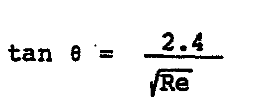
- angle between said fin base line and said line connecting said louvers is in the range of 5 to 15 degrees.
- said maximum height of said louver satisfies the following formulae: and where e is said angle, Pf is the fin pitch, b is the width of the louver and Re is the Reynolds number.
- corrugated fins 1 each of which is bent in serpentine manner are disposed between adjacent parts of a flat fluid tube 31 which is bent also in a serpentine manner through a cold working.
- the corrugated fins 1 and the flat fluid tube 31 are brazed or soldered in a high temperature furnace to form a heat exchanger structure.
- the heat exchanger structure is provided with an inner fluid inlet tube 33 and an inner fluid outlet tube 34. With such a structure, a heat exchange is performed between a coolant flowing within the flat fluid tube 31 and an air flowing outside the tube 31 through the corrugated fins 1.
- reference characters 5a, 5b, 5c and 5d denote severed and raised louvers which will hereinafter be simply referred to as "louvers" formed in the fins 1.
- Reference characters la, Ib and lc denote fin bases remaining after severing and raising the louvers 5. In the embodiment shown, four louvers are formed between the remaining fin bases la, Ib and Ic.
- a line 3 represents a fin base line
- lines 10a and 10b represent a direction of the louver arrangement.
- the louvers 5a, 5b, 5c, 5d, ... are punched in an alternate or staggered manner in the opposite directions with respect to the fin base line 3.
- the louvers 5a, 5b, 5c and 5d are formed to have different raised heights substantially in a symmetrical relationship with respect to a midpoint between the adjacent pair of the remaining fin bases la and lb.
- the respective louvers and the remaining fin bases on the same side with respect to the fin base line 3 are arranged in a stepped manner along lines 10a and 10b which slant at a predetermined constant angle 9 with respect to the fin base line 3 that is in parallel with the flow of fluid.
- a distance from each adjacent louvers in the direction of air is kept substantially constant.
- a dimension of a minimum louver gap 6 min defined between the remaining fin base la and the louver 5a and between the remaining fin base Ib and the louver 5d may be kept large since that minimum dimension is not restricted by the louver width in the air flow direction.
- the air flow 101 are uniformly branched between the respective louvers and the air as a whole flows linearly, since the louvers are arranged in the stepped manner along the lines 10a and 10b as shown in Fig. 3. Therefore, a possible pressure loss may be suppressed.
- Each thermal boundary layer 100 formed on a louver 5 is cut by every louver, without any adverse effect to downstream louvers. Thus, all the louvers may be used to fullfil their heat transfer function.
- louvers and the remaining fin bases located on the same side of the fin base line 3 along the lines slanted at the constant angle e with respect to the fin base one 3 are arranged in the stepped manner. Therefore, even if the width of the louvers is decreased, the louver gap may be kept sufficiently, and the air flow may well follow the respective louver substantially uniformly. The thermal boundary layers formed on the louvers will not be grown but be cut. For this reason, the "edge effect" of the respective louver may be exhibited to a maximum possible extent. Therefore, it is possible to decrease the louver width up to approximately 0.5 mm.
- a heat transfer efficiency of the fin structure according to the present invention is considerably superior to that of a conventional fin structure.
- the fin structure is such that the louvers 5a, 5c (5b, 5d) embraces the remaining fin base (la, Ib, Ic, ...) to support the fin I on both sides in a symmetrical manner. Therefore, a mechanical resistance against a buckling deformation caused by brazing is increased. This makes it possible to thin the fin base plate much more for practical use and to reduce a cost for material of the heat exchange to provide an inexpensive heat exchanger.
- louvers are severed and raised between the adjacent remaining fin bases, by way of example. It is apparent that the even number, not smaller than six, of louvers may be formed.
- Figs. 5 and 6 show embodiments in which the even number, not smaller than six, of the louvers are formed between the adjacent remaining fin bases. More specifically, Fig. 5 shows an embodiment in which six louvers are severed and raised between the adjacent remaining fin bases, and Fig. 8 shows an embodiment in which eight louvers are severed-and raised between the adjacent remaining fin bases. Also, in these embodiments, the louvers are severed and raised alternately on the opposite sides of the fin base line like bridges, and heights of the louvers on each side are defined along the line inclined or slanted at a constant angle e with respect to the fin base line 3 that is in parallel with the flow of the air.
- the louver arrangement direction expressed by a slant angle e defined between a fin base line and the line connecting the most raised louver and the remaining fin base is kept constant.
- the louver arrangement direction slanted by a constant angle o with respect to the fin base line may be changed in every louver group between the remaining fin bases or in every plural louver groups.
- six louvers are severed and raised between the adjacent remaining fin bases in a staggered manner, with heights of the louvers located on the same side with respect to the fin base line being varied along a line slanted at a constant angle e.
- the directions of the slant defined by the angle e are changed in an alternate manner in every louver group of the alternately severed and raised louvers between the remaining fin bases.
- a group of louvers 5a to 5f between the remaining fin bases are arranged downwardly at an angle 6 with respect to the fin base line, whereas an adjacent group of louvers 5a to 5f are arranged upwardly at an angle e with respect to the fin base line, so that the directions defined by the angle e are changed in an alternate manner in every louver group.
- the fin base portion in which the louvers are to be formed is made ductile by a cutting and raising work for the purpose of forming the louvers.
- the louvers tend to be restored to the original shape due to springback or resiliency.
- compression stresses are exerted to the remaining fin bases la, Ib, lc, ... to which the work is not applied.
- the relative positions of the remaining fin bases with respect to the louvers will not be stabilized.
- buckled portions are formed in the remaining fin base plate to absorb the compression stresses with the buckled portions.
- the buckled portions may be formed by bending parts of the remaining fin bases in V-shapes or U-shapes in a direction perpendicular to the flow of the air, for example. Also, instead of the formation of the buckled portions in the remaining fin bases, it is possible to fold back parts of the remaining fin bases in the direction in parallel with the air flow, to thereby increase mechanical strength of the remaining fin bases to prevent the generation of the formation of the remaining fin bases.
- Fig. 8 shows the comparison of the experimental results of the heat transfer coefficients in case of changing a relative positional shift S between the louvers on one which is diposed on the downstream side by a distance corresponding to a width of the single louver, It is appreciated that the fin according to the embodiments is much superior in heat transfer performance to the conventional fin. In particular, it is appreciated that, in the conventional fin, the performance is considerably degraded at the relative positional shift S in the range of 0.4 to 0.2 mm, whereas, in the fin according to the embodiments, the performance is not changed remarkably.
- Fig. 9 shows this distinction more clearly. In Fig. 9, the same date are used but the heat transfer coefficients are plotted in accordance the minimum louver gaps smin.
- the minimum louver gap be large as much as possible.
- the minimum louver gap smin would be increased, the relative louver positional shift S would be small so that the considerable performance reduction would be noticed as shown in Figs. 8 and 9.
- the heat transfer coefficients are considerably improved in the region (0.7 to 0.8 mm) in which the minimum gap is larger than that of the conventional fin. According to the fin of the invention, the fin clogging due to the water droplets formed on the fin surfaces or dusts may be prevented, to thereby provide a heat exchanger having a high heat transfer performance.
- Figs. 8 and 9 are concerned with the louver arrangement of the louvers having a fin pitch Pf of 2 mm, a louver width b of I mm and a thickness t of 0.1 mm, but these dimensions may of course be changed in accordance with the desired design.
- a maximum raised height Hmax is restricted in view of shaping work with a limit of elongation or ductility of the fin material for the raised louver.
- the arrangement pitch (fin pitch) Pf of the fin base plate of the air-conditioner heat exchanger is about 1.5 to 3 mm, and it is preferable to substantially establish the relationship, Hmax ⁇ Pf/2.
- the louver minimum gap 6min is smaller than that given by the following formula: where t is a louver thickness (m).
- the fin structure has a small resistance against the clogging of the louver due to the water formed on the fin surface, dusts or the like.
- the louver 5d and the louver 5d' are aligned with each other on the same line, so that the entailed flows of the upstream louver would affects the downstream louver to thereby reduce the heat transfer efficiency.
- the maximum raised height Hmax be defined by the following formulae (9) and (10) in view of the condition that the relative positional shift S of the louvers separated by the distance corresponding to the width of the single louver be greater than the thickness 8 of the boundary layer as illustrated in Fig. 10.
- Fig. 14 is a perspective view of a cross fin tube type heat exchanger constructed so that a plurality of circular tubes 47 are adapted to pass through fins I.
- Fig. 15 is a partial cross-sectional view taken along a line that is in parallel with the fins I in Fig. 14.
- Fig. 16 is a cross-sectional view of a louver group taken along the line XVI-XVI.Also, in such a heat exchanger construction, the louver cross-section is the same as illustrated before. Therefore, the same effects and advantages are insured in the heat exchanger shown in Figs. 14 to 16.
- the structure shown in Figs. 14 to 16 has a high resistance against the clogging due to the water droplets formed on the fin surfaces or the dusts entrained in the air flow, thus providing a cross-fin tube type heat exchanger having a high heat transfer performance.
- louvers having an even number are severed and raised, in series, in a staggered manner with respect to the fin base line, and every two louvers (including fin bases) are arranged in a stepped manner in a direction slanted at a constant angle e with respect to the fin base line. Accordingly, a minimum louver gap may be large.
- the heat exchanger according to the present invention has a high clog-proof property against the water droplets, dusts or any other foreign matters with. a high heat transfer performance.
- the louvers are symmetrical with respect to the fin base plate, so that the buckling resistance strength is increased during the brazing or soldering works, which leads to a high productivity.
Landscapes
- Engineering & Computer Science (AREA)
- Physics & Mathematics (AREA)
- Thermal Sciences (AREA)
- Mechanical Engineering (AREA)
- General Engineering & Computer Science (AREA)
- Geometry (AREA)
- Heat-Exchange Devices With Radiators And Conduit Assemblies (AREA)
Description
- The invention relates to a heat exchanger comprising a number of fins and at least one heat transfer tube held in contact with said fins, said fins being severed to form slits therein and altemately raised to form bridge-like louvers in a staggered manner with respect to a fin base line.
- Such a heat exchanger-is described in US-A-21 33 502. In the fin arrangement of this heat exchanger each of the louvers raised from a fin varies in heigt along its longitudinal direction. As a result, the louver arranged just downstreams of a fin base comes at its one end into the thermal boundary layer entailed downstream of the fin base. The same can be said of another fin base arranged just downstream of another louver. Thus, the fin arrangement of this reference does not have a high heat transfer effectivity. Moreover, the openings defined by the louvers and fin bases are of wedge-like shapes as viewed in the direction of flow of air. This means that in this fin arrangement wide passage portions through which air flows readily and narrow passage portions through which air scarcely flows are alternately arranged along an air flow passage. Accordingly, an inappropriate large volume of air flows through the wide passage portions with the result of insufficient heat exchange between the air and the fin, while the narrow passage portions are not supplied with the necessary volume of air for the heat exchange, so that this fin arrangement as a whole cannot perform the exchange of heat with high efficiency. The narrow portions of the openings are apt to be plugged or get clogged with water droplets and dust, thereby further increasing the resistance to the air flow.
- Another heat exchanger, described in the DE-A-31 31 737 shows a fin arrangement with louvers which are located on the upper side with respect to the fin base and which are equal in height to each other. This can be also said of the louvers located on the lower side, because between adjacent fin bases only one louver is formed. Accordingly, for the louvers of each group located on the same side with respect to the fin base, it is impossible to be arranged along any line extending at an angle to the fin base. The louver is not raised upwardly from the associated fin base, but is raised downwardly from another fin base of an adjacent row.
- It is the object of the invention to provide a heat exchanger of the generic kind having a fin arrangement, which may effect a high heat transfer performance by preventing downstream louvers of a fin from being influenced by strip streams or trailing flows of upstream louvers, and which is not clogged with water droplets or dust in the air.
- According to the invention this object is obtained with a heat exchanger of the generic kind in that the number of said louvers grouped in a louver group between a first fin base and a second fin base is an even number not smaller than four; in that the louver of said louver group closest to said first fin base has a maximum raised height; and in that the louvers of said louver group located each on the same side with respect to said fin base line are arranged along a line which connects points at the same outer edges of the respective louvers and an adjacent fin base and which is inclined at a predetermined constant angle with respect to the fin base line.
- With such an arrangement, each downstream louver or fin base is located out of a thermal boundary layer which is generated at the corresponding upstream louver or fin base and entailed downstream thereof so that the fin arrangement as a whole has a high heat transfer performance. Further respective openings defined by the louvers and fin bases are of a substantially rectangular shape as viewed in the direction of flow of air, so that the resistance to the air flow at the openings is uniform over the fin arrangement, the thus formed smooth and uniform air flow ensures a high heat transfer between the air and the fin. Moreover, the rectangular openings which are defined by the louvers and fin bases arranged in a staggered manner provide air flow passages of large areas each of which has a constant height so that they are effectively prevented from getting clogged with water droplets and dust.
- It is preferred that the angle between said fin base line and said line connecting said louvers is in the range of 5 to 15 degrees.
- Advantageously the said maximum height of said louver satisfies the following formulae:

- Further it is convenient that said angle between said fin base line and said line connecting said louvers is alternately changed for one or more louver groups. In the following embodiments of the invention are described with the aid of drawings.
- Fig. 1 is a perspective view showing a primary part of the heat exchanger for an automotive air-conditioner,
- Fig. 2 is a perspective view showing the overall appearance of the heat exchanger,
- Fig. 3 is a cross-sectional view, taken along the line III-III of Fig. 1, showing the primary part of the heat exchanger illustrating flows of fluid therealong,
- Fig. 4 is a front elevational view showing a fin structure,
- Fig. 5 to 7 are cross-sectional views of louver portions of fins in accordance with other embodiments of the invention;
- Figs. 8 and 9 show comparisons in performance between the present invention and the prior art;
- Fig. 10 is a graph showing a relationship between louver arrangement slant angles 6 and Reynolds numbers according to the present invention;
- Fig. 11 is a view illustrating a maximum raised height Hmax of a heat exchanger fin structure according to an embodiment of the invention;
- Figs. 12 and 13 are an enlarged view of primary parts of heat exchangers in accordance with the invention, showing water droplet adhering states;
- Fig. 14 is a perspective view showing a heat exchanger in accordance with still another embodiment of the invention;
- Fig. 15 is a cross-sectional view of a part of the heat exchanger shown in Fig. 14; and
- Fig. 16 is a cross-sectional view taken along the line XVI-XVI of Fig. 15.
- As shown in Fig. 2, corrugated
fins 1 each of which is bent in serpentine manner are disposed between adjacent parts of aflat fluid tube 31 which is bent also in a serpentine manner through a cold working. Thecorrugated fins 1 and theflat fluid tube 31 are brazed or soldered in a high temperature furnace to form a heat exchanger structure. Then, the heat exchanger structure is provided with an innerfluid inlet tube 33 and an innerfluid outlet tube 34. With such a structure, a heat exchange is performed between a coolant flowing within theflat fluid tube 31 and an air flowing outside thetube 31 through thecorrugated fins 1. - In Fig. 1,
reference characters fins 1. Reference characters la, Ib and lc denote fin bases remaining after severing and raising thelouvers 5. In the embodiment shown, four louvers are formed between the remaining fin bases la, Ib and Ic. - In Fig. 3, a
line 3 represents a fin base line, andlines 10a and 10b represent a direction of the louver arrangement. Thelouvers fin base line 3. Thelouvers fin base line 3 are arranged in a stepped manner alonglines 10a and 10b which slant at a predetermined constant angle 9 with respect to thefin base line 3 that is in parallel with the flow of fluid. - According to the foregoing embodiment, with such an arrangement, a distance from each adjacent louvers in the direction of air is kept substantially constant. Also, a dimension of a minimum louver gap 6min defined between the remaining fin base la and the
louver 5a and between the remaining fin base Ib and thelouver 5d may be kept large since that minimum dimension is not restricted by the louver width in the air flow direction. - When the air is caused to flow in the direction indicated by the arrow A and to enter the heat exchanger, the air flow 101 are uniformly branched between the respective louvers and the air as a whole flows linearly, since the louvers are arranged in the stepped manner along the
lines 10a and 10b as shown in Fig. 3. Therefore, a possible pressure loss may be suppressed. Eachthermal boundary layer 100 formed on alouver 5 is cut by every louver, without any adverse effect to downstream louvers. Thus, all the louvers may be used to fullfil their heat transfer function. - As described above, the louvers and the remaining fin bases located on the same side of the
fin base line 3 along the lines slanted at the constant angle e with respect to the fin base one 3 are arranged in the stepped manner. Therefore, even if the width of the louvers is decreased, the louver gap may be kept sufficiently, and the air flow may well follow the respective louver substantially uniformly. The thermal boundary layers formed on the louvers will not be grown but be cut. For this reason, the "edge effect" of the respective louver may be exhibited to a maximum possible extent. Therefore, it is possible to decrease the louver width up to approximately 0.5 mm. A heat transfer efficiency of the fin structure according to the present invention is considerably superior to that of a conventional fin structure. - As best shown in Fig. 4, the fin structure is such that the
louvers - In the foregoing embodiment, four louvers are severed and raised between the adjacent remaining fin bases, by way of example. It is apparent that the even number, not smaller than six, of louvers may be formed.
- Figs. 5 and 6 show embodiments in which the even number, not smaller than six, of the louvers are formed between the adjacent remaining fin bases. More specifically, Fig. 5 shows an embodiment in which six louvers are severed and raised between the adjacent remaining fin bases, and Fig. 8 shows an embodiment in which eight louvers are severed-and raised between the adjacent remaining fin bases. Also, in these embodiments, the louvers are severed and raised alternately on the opposite sides of the fin base line like bridges, and heights of the louvers on each side are defined along the line inclined or slanted at a constant angle e with respect to the
fin base line 3 that is in parallel with the flow of the air. - In the foregoing embodiments, the louver arrangement direction expressed by a slant angle e defined between a fin base line and the line connecting the most raised louver and the remaining fin base is kept constant. However, according to the present invention the louver arrangement direction slanted by a constant angle o with respect to the fin base line may be changed in every louver group between the remaining fin bases or in every plural louver groups. In an embodiment shown in Fig. 7, six louvers are severed and raised between the adjacent remaining fin bases in a staggered manner, with heights of the louvers located on the same side with respect to the fin base line being varied along a line slanted at a constant angle e. Further, in Fig. 7, the directions of the slant defined by the angle e are changed in an alternate manner in every louver group of the alternately severed and raised louvers between the remaining fin bases. In other words, in Fig. 7, a group of
louvers 5a to 5f between the remaining fin bases are arranged downwardly at anangle 6 with respect to the fin base line, whereas an adjacent group oflouvers 5a to 5f are arranged upwardly at an angle e with respect to the fin base line, so that the directions defined by the angle e are changed in an alternate manner in every louver group. - In the foregoing embodiment, the fin base portion in which the louvers are to be formed is made ductile by a cutting and raising work for the purpose of forming the louvers. After completion of the work, the louvers tend to be restored to the original shape due to springback or resiliency. As a result, compression stresses are exerted to the remaining fin bases la, Ib, lc, ... to which the work is not applied. The relative positions of the remaining fin bases with respect to the louvers will not be stabilized. In order to prevent this phenomenon, buckled portions are formed in the remaining fin base plate to absorb the compression stresses with the buckled portions. The buckled portions may be formed by bending parts of the remaining fin bases in V-shapes or U-shapes in a direction perpendicular to the flow of the air, for example. Also, instead of the formation of the buckled portions in the remaining fin bases, it is possible to fold back parts of the remaining fin bases in the direction in parallel with the air flow, to thereby increase mechanical strength of the remaining fin bases to prevent the generation of the formation of the remaining fin bases.
- Comparative results in heat transfer performance between the fins of the heat exchanger in accordance with the embodiments of the invention and the conventional fins in which the louvers are alternately severed and raised without any remaining fin bases will be explained with reference to Figs. 8 and 9. The performance comparative experiments were conducted in accordance with a method of measuring heat transfer coefficiencies by using thermistor heaters. Each of the thermistor heaters that were used in the experiments had a thickness of I mm, a louver length b of 10 mm and an entire width of 150 mm. Eleven raws of these thermistor heaters are arranged in the air flow direction, to form a louver group corresponding to an actual fin arrangement having a fin pitch Pf of 2 mm, a louver width of 1.0 mm. The thermistor heater corresponding to the single louver severed and raised from the fin bases plate where heated with electric supply. The heat transfer coefficient was obtained by the following formulae:
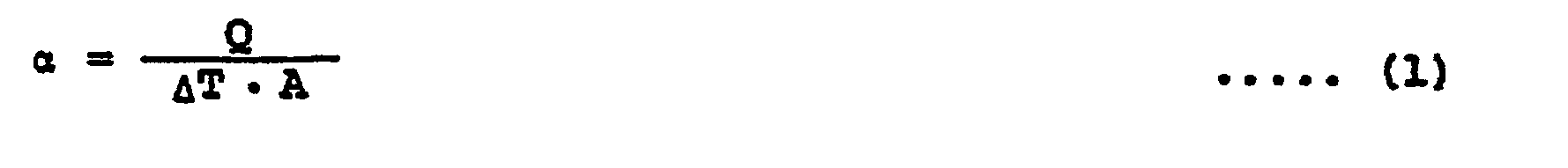


- QH: the generated heat quantity (W) of the heater,
- Qf: the heat loss (W),
- A : the heat transfer are (m2) over which the heater and the air were contacted,
- AT: the temperature difference (°C) between the surface of the thermistor heater and the air at the inlet,
- Tw : the surface temperature (°C) of the thermistor heater, and
- Tai : the temperature (°C) of the air at the inlet.
- In order to obtain the performance of the actual fin, the well known Reynolds number Re and Nusselt number Nu were used.


- Fig. 8 shows the comparison of the experimental results of the heat transfer coefficients in case of changing a relative positional shift S between the louvers on one which is diposed on the downstream side by a distance corresponding to a width of the single louver, It is appreciated that the fin according to the embodiments is much superior in heat transfer performance to the conventional fin. In particular, it is appreciated that, in the conventional fin, the performance is considerably degraded at the relative positional shift S in the range of 0.4 to 0.2 mm, whereas, in the fin according to the embodiments, the performance is not changed remarkably. Fig. 9 shows this distinction more clearly. In Fig. 9, the same date are used but the heat transfer coefficients are plotted in accordance the minimum louver gaps smin. It is preferable that, in an automotive air cooler, since moisture in the air is condensed on the fin surfaces to form water droplets, the minimum louver gap be large as much as possible. However, in this conventional fin, the minimum louver gap smin would be increased, the relative louver positional shift S would be small so that the considerable performance reduction would be noticed as shown in Figs. 8 and 9. In contrast, in the fin according to the present invention, the heat transfer coefficients are considerably improved in the region (0.7 to 0.8 mm) in which the minimum gap is larger than that of the conventional fin. According to the fin of the invention, the fin clogging due to the water droplets formed on the fin surfaces or dusts may be prevented, to thereby provide a heat exchanger having a high heat transfer performance.
- Incidentally, the data shown in Figs. 8 and 9 are concerned with the louver arrangement of the louvers having a fin pitch Pf of 2 mm, a louver width b of I mm and a thickness t of 0.1 mm, but these dimensions may of course be changed in accordance with the desired design.
- A suitable range of the slant angle of the louver arrangement in accordance with the embodiments of the invention will be explained in view of actual factors such as adhesion of water droplet or the like.
- A
boundary layer thickness 8 of a trailing flow generated downstream of the flat plate disposed in a uniform air flow corresponds to a thermal boundary layer that is generated on the louver and entailed on the downstream side to affect the performance of the downstream louvers. Therefore, it is preferable that the relative positional shift S between the upstream louver and the downstream louver be larger than thethickness 8 of the boundary layer. Then, the lower limits of the arrangement slant angle e may be obtained assuming that a relationship S = 8, as shown in Fig. 10. In Fig. 10, an abscissa of the graph of Fig. 10 represent a Reynolds number given by the formula (4). The parameters availably used in the air-conditioner heat exchanger are specified as follows: b = I to 2 mm, vf = I to 5 W/s, and Re = 100 to 600. A small angle e in the range of 5 to 15 degrees may suffice. - For a raised height of the louver severed from the fin base, a maximum raised height Hmax is restricted in view of shaping work with a limit of elongation or ductility of the fin material for the raised louver. Normally, the arrangement pitch (fin pitch) Pf of the fin base plate of the air-conditioner heat exchanger is about 1.5 to 3 mm, and it is preferable to substantially establish the relationship, Hmax ≦ Pf/2. However, when the height Hmax is small as shown in Fig. II, the louver minimum gap 6min is smaller than that given by the following formula:

- Figs. 12 and 13 show observation results of the water adhesion states in an evaporator for an automotive air-conditioner. The observations were carried out under the condition that the air temperature was 25°C, the relative humidity was 60% and the front air flow velocity vf = 2 m/s, with cold water at a temperature of 5°C flowing through the tubes.
- As a result of the observations, the following phenomena were noted:
- (I) The
water droplets 50 formed on the fin surfaces were sucked to Y-shaped, severed portions at louver proximal ends in openingportions 40 and 40' formed by cutting and raising the louvers. - (2) The droplets were collected at wedge-shaped spaces formed at connecting portions between fins I and the
flat tube 31 and flowed down along the connecting portions to be discharged in the direction indicated by the arrows D in Figs. 12 and 13. - (3) The water drain velocity was restricted so that the
water droplets 50 were always remaining at the Y-shaped, severed portions at the louver proximal ends during the operation. In particular, in the case where the minimum louver gap 6min was small, the large amount of water was left thereat. - From the above observation results, it was appreciated that the minimum louver gap 8min had to be enlarged in order to prevent the clogging by the water droplets; that is, the maximum louver raised height Hmax in Fig. II had to be increased.
- In the case where the maximum raised height Hmax is given in view of the work limits as follows:

louver 5d and thelouver 5d' are aligned with each other on the same line, so that the entailed flows of the upstream louver would affects the downstream louver to thereby reduce the heat transfer efficiency. - Accordingly, based upon the foregoing discussions, it is preferable that the maximum raised height Hmax be defined by the following formulae (9) and (10) in view of the condition that the relative positional shift S of the louvers separated by the distance corresponding to the width of the single louver be greater than the
thickness 8 of the boundary layer as illustrated in Fig. 10.

- Still another embodiment of the present invention will now be explained with reference to Figs. 14 to 16. Fig. 14 is a perspective view of a cross fin tube type heat exchanger constructed so that a plurality of
circular tubes 47 are adapted to pass through fins I. Fig. 15 is a partial cross-sectional view taken along a line that is in parallel with the fins I in Fig. 14. Fig. 16 is a cross-sectional view of a louver group taken along the line XVI-XVI.Also, in such a heat exchanger construction, the louver cross-section is the same as illustrated before. Therefore, the same effects and advantages are insured in the heat exchanger shown in Figs. 14 to 16. In other words, the structure shown in Figs. 14 to 16 has a high resistance against the clogging due to the water droplets formed on the fin surfaces or the dusts entrained in the air flow, thus providing a cross-fin tube type heat exchanger having a high heat transfer performance. - As described above, according to the present invention, four or more louvers having an even number are severed and raised, in series, in a staggered manner with respect to the fin base line, and every two louvers (including fin bases) are arranged in a stepped manner in a direction slanted at a constant angle e with respect to the fin base line. Accordingly, a minimum louver gap may be large. The heat exchanger according to the present invention has a high clog-proof property against the water droplets, dusts or any other foreign matters with. a high heat transfer performance. Also, the louvers are symmetrical with respect to the fin base plate, so that the buckling resistance strength is increased during the brazing or soldering works, which leads to a high productivity.
Claims (4)


Applications Claiming Priority (2)
| Application Number | Priority Date | Filing Date | Title |
|---|---|---|---|
| JP195870/85 | 1985-09-06 | ||
| JP60195870A JPS6256786A (en) | 1985-09-06 | 1985-09-06 | Heat exchanger |
Publications (2)
| Publication Number | Publication Date |
|---|---|
| EP0215344A1 EP0215344A1 (en) | 1987-03-25 |
| EP0215344B1 true EP0215344B1 (en) | 1990-03-14 |
Family
ID=16348355
Family Applications (1)
| Application Number | Title | Priority Date | Filing Date |
|---|---|---|---|
| EP86111780A Expired - Lifetime EP0215344B1 (en) | 1985-09-06 | 1986-08-26 | Heat exchanger |
Country Status (5)
| Country | Link |
|---|---|
| US (1) | US4756362A (en) |
| EP (1) | EP0215344B1 (en) |
| JP (1) | JPS6256786A (en) |
| KR (1) | KR900007725B1 (en) |
| DE (1) | DE3669585D1 (en) |
Cited By (1)
| Publication number | Priority date | Publication date | Assignee | Title |
|---|---|---|---|---|
| CN109443071A (en) * | 2018-10-30 | 2019-03-08 | 珠海格力电器股份有限公司 | Radiating fin and radiator |
Families Citing this family (34)
| Publication number | Priority date | Publication date | Assignee | Title |
|---|---|---|---|---|
| JPH0827150B2 (en) * | 1986-07-21 | 1996-03-21 | 松下冷機株式会社 | Heat exchanger |
| JPH0743236B2 (en) * | 1987-07-10 | 1995-05-15 | 株式会社日立製作所 | Heat exchanger |
| JPH01111965U (en) * | 1988-01-21 | 1989-07-27 | ||
| US4958681A (en) * | 1989-08-14 | 1990-09-25 | General Motors Corporation | Heat exchanger with bypass channel louvered fins |
| US5099914A (en) * | 1989-12-08 | 1992-03-31 | Nordyne, Inc. | Louvered heat exchanger fin stock |
| KR970047747A (en) * | 1995-12-28 | 1997-07-26 | 배순훈 | Heat exchanger fin structure for air conditioner |
| KR100197718B1 (en) * | 1996-12-30 | 1999-06-15 | 윤종용 | Heat exchanger of air conditioner |
| DE19813989A1 (en) * | 1998-03-28 | 1999-09-30 | Behr Gmbh & Co | Heat exchanger, particularly for road vehicles |
| GB2354817A (en) * | 1999-09-29 | 2001-04-04 | Ford Motor Co | Fin construction |
| WO2005075917A1 (en) * | 2004-02-05 | 2005-08-18 | Calsonic Kansei Uk Limited | Heat exchanger |
| CN2750420Y (en) * | 2004-04-23 | 2006-01-04 | 鸿富锦精密工业(深圳)有限公司 | Optical recording/reproducing device |
| JP2006153327A (en) * | 2004-11-26 | 2006-06-15 | Daikin Ind Ltd | Heat exchanger |
| JP2006322698A (en) * | 2005-04-22 | 2006-11-30 | Denso Corp | Heat exchanger |
| KR100668806B1 (en) * | 2005-06-17 | 2007-01-16 | 한국과학기술연구원 | Louver fin heat exchanger with improved heat exchange efficiency by controlling water buildup |
| DE102005056642A1 (en) * | 2005-11-28 | 2007-05-31 | J. Eberspächer GmbH & Co. KG | A heat exchanger assembly for a device for conditioning air to be introduced into a vehicle interior |
| US20070137849A1 (en) * | 2005-12-15 | 2007-06-21 | Toshiba International Corporation | Heatsink with offset fins |
| JP2007212009A (en) * | 2006-02-07 | 2007-08-23 | Sanden Corp | Heat exchanger |
| GB0622355D0 (en) * | 2006-11-09 | 2006-12-20 | Oxycell Holding Bv | High efficiency heat exchanger and dehumidifier |
| US20090173479A1 (en) * | 2008-01-09 | 2009-07-09 | Lin-Jie Huang | Louvered air center for compact heat exchanger |
| US20150000880A1 (en) * | 2008-08-06 | 2015-01-01 | Delphi Technologies, Inc. | Heat exchanger with varied louver angles |
| US20130199760A1 (en) * | 2008-08-06 | 2013-08-08 | Delphi Technologies, Inc. | Heat exchanger assembly having split mini-louvered fins |
| EP2452148A1 (en) * | 2009-07-07 | 2012-05-16 | A-heat Allied Heat Exchange Technology Ag | Heat exchange system and method for operating a heat exchange system |
| US8875780B2 (en) * | 2010-01-15 | 2014-11-04 | Rigidized Metals Corporation | Methods of forming enhanced-surface walls for use in apparatae for performing a process, enhanced-surface walls, and apparatae incorporating same |
| KR20120044850A (en) * | 2010-10-28 | 2012-05-08 | 삼성전자주식회사 | Heat exchanger |
| JP5257485B2 (en) * | 2011-05-13 | 2013-08-07 | ダイキン工業株式会社 | Heat exchanger |
| NL2007827C2 (en) * | 2011-11-21 | 2013-05-23 | Oxycom Beheer Bv | Heat exchange matrix. |
| JP6333571B2 (en) * | 2014-02-10 | 2018-05-30 | 三菱重工オートモーティブサーマルシステムズ株式会社 | Offset fin for heat exchanger and refrigerant heat exchanger using the same |
| JP6327271B2 (en) * | 2015-04-17 | 2018-05-23 | 株式会社デンソー | Heat exchanger |
| JP6747384B2 (en) * | 2017-06-12 | 2020-08-26 | 株式会社デンソー | Heat exchanger and corrugated fins |
| CN110741217B (en) * | 2017-06-12 | 2021-11-09 | 株式会社电装 | Heat exchanger and corrugated fin |
| US11175053B2 (en) * | 2017-06-22 | 2021-11-16 | Mitsubishi Electric Corporation | Heat exchanger, refrigeration cycle device, and air-conditioning apparatus |
| US11402163B2 (en) * | 2018-11-14 | 2022-08-02 | Cooler Master Co., Ltd. | Heat dissipation device and fin structure |
| US12078431B2 (en) * | 2020-10-23 | 2024-09-03 | Carrier Corporation | Microchannel heat exchanger for a furnace |
| RU210249U1 (en) * | 2021-12-03 | 2022-04-04 | федеральное государственное бюджетное образовательное учреждение высшего образования "Белгородский государственный технологический университет им. В.Г. Шухова" | PANEL RADIATOR |
Family Cites Families (9)
| Publication number | Priority date | Publication date | Assignee | Title |
|---|---|---|---|---|
| US2133502A (en) * | 1936-05-22 | 1938-10-18 | Gen Motors Corp | Radiator fin structure |
| US2789797A (en) * | 1953-08-20 | 1957-04-23 | Modine Mfg Co | Heat exchanger fin structure |
| FR1212901A (en) * | 1958-03-14 | 1960-03-28 | Talalmanyokat Ertekesito Vall | non-uniformly arranged interrupted fin heat exchanger |
| US3438433A (en) * | 1967-05-09 | 1969-04-15 | Hudson Eng Co | Plate fins |
| US4019494A (en) * | 1975-07-09 | 1977-04-26 | Safdari Yahya B | Solar air heater assembly |
| JPS5737696A (en) * | 1980-08-15 | 1982-03-02 | Hitachi Ltd | Heat exchanger |
| JPS5795595A (en) * | 1980-12-03 | 1982-06-14 | Hitachi Ltd | Fin for heat exchanger unit |
| JPS57144892A (en) * | 1981-02-28 | 1982-09-07 | Daikin Ind Ltd | Gross-fin coil type heat exchanger |
| JPS6020094A (en) * | 1983-07-13 | 1985-02-01 | Mitsubishi Electric Corp | Heat exchanger |
-
1985
- 1985-09-06 JP JP60195870A patent/JPS6256786A/en active Granted
-
1986
- 1986-06-30 KR KR1019860005269A patent/KR900007725B1/en not_active Expired
- 1986-08-12 US US06/895,847 patent/US4756362A/en not_active Expired - Lifetime
- 1986-08-26 DE DE8686111780T patent/DE3669585D1/en not_active Expired - Lifetime
- 1986-08-26 EP EP86111780A patent/EP0215344B1/en not_active Expired - Lifetime
Cited By (2)
| Publication number | Priority date | Publication date | Assignee | Title |
|---|---|---|---|---|
| CN109443071A (en) * | 2018-10-30 | 2019-03-08 | 珠海格力电器股份有限公司 | Radiating fin and radiator |
| CN109443071B (en) * | 2018-10-30 | 2019-12-17 | 珠海格力电器股份有限公司 | Radiating fin and radiator |
Also Published As
| Publication number | Publication date |
|---|---|
| KR870003368A (en) | 1987-04-16 |
| US4756362A (en) | 1988-07-12 |
| JPS6256786A (en) | 1987-03-12 |
| KR900007725B1 (en) | 1990-10-19 |
| JPH0577959B2 (en) | 1993-10-27 |
| EP0215344A1 (en) | 1987-03-25 |
| DE3669585D1 (en) | 1990-04-19 |
Similar Documents
| Publication | Publication Date | Title |
|---|---|---|
| EP0215344B1 (en) | Heat exchanger | |
| CA2050281C (en) | Heat exchangers | |
| EP1106951B1 (en) | Continuous combination fin for a heat exchanger | |
| CA1313183C (en) | Embossed plate heat exchanger | |
| US4676304A (en) | Serpentine-type heat exchanger having fin plates with louvers | |
| US5669438A (en) | Corrugated cooling fin with louvers | |
| CA1064902A (en) | Heat exchange device | |
| US6675878B2 (en) | Angled turbulator for use in heat exchangers | |
| US4958681A (en) | Heat exchanger with bypass channel louvered fins | |
| US6170566B1 (en) | High performance louvered fin for a heat exchanger | |
| EP0632878B1 (en) | Heat exchanger tube | |
| US6942024B2 (en) | Corrugated heat exchange element | |
| CN101341372A (en) | Novel heat exchanger corrugations and applications thereof | |
| US5975200A (en) | Plate-fin type heat exchanger | |
| US5476140A (en) | Alternately staggered louvered heat exchanger fin | |
| CN1097718C (en) | Fined tube heat-exchanger | |
| CA2214255C (en) | Heat exchanger turbulizers with interrupted convolutions | |
| EP0803695B1 (en) | Plate-fin heat exchanger | |
| EP3575728B1 (en) | A core of a heat exchanger comprising corrugated fins | |
| JPH0545474U (en) | Heat exchanger | |
| JPH0743236B2 (en) | Heat exchanger | |
| JPH0331693A (en) | heat exchanger with fins | |
| CN1147699C (en) | Cooling elements for heat exchangers | |
| JPH1123179A (en) | Finned heat exchanger | |
| EP0097612A2 (en) | Heat exchanger |
Legal Events
| Date | Code | Title | Description |
|---|---|---|---|
| PUAI | Public reference made under article 153(3) epc to a published international application that has entered the european phase |
Free format text: ORIGINAL CODE: 0009012 |
|
| 17P | Request for examination filed |
Effective date: 19860826 |
|
| AK | Designated contracting states |
Kind code of ref document: A1 Designated state(s): DE FR GB |
|
| 17Q | First examination report despatched |
Effective date: 19880105 |
|
| GRAA | (expected) grant |
Free format text: ORIGINAL CODE: 0009210 |
|
| AK | Designated contracting states |
Kind code of ref document: B1 Designated state(s): DE FR GB |
|
| REF | Corresponds to: |
Ref document number: 3669585 Country of ref document: DE Date of ref document: 19900419 |
|
| ET | Fr: translation filed | ||
| PLBE | No opposition filed within time limit |
Free format text: ORIGINAL CODE: 0009261 |
|
| STAA | Information on the status of an ep patent application or granted ep patent |
Free format text: STATUS: NO OPPOSITION FILED WITHIN TIME LIMIT |
|
| 26N | No opposition filed | ||
| PGFP | Annual fee paid to national office [announced via postgrant information from national office to epo] |
Ref country code: FR Payment date: 19920630 Year of fee payment: 7 |
|
| PGFP | Annual fee paid to national office [announced via postgrant information from national office to epo] |
Ref country code: GB Payment date: 19920814 Year of fee payment: 7 |
|
| PG25 | Lapsed in a contracting state [announced via postgrant information from national office to epo] |
Ref country code: GB Effective date: 19930826 |
|
| GBPC | Gb: european patent ceased through non-payment of renewal fee |
Effective date: 19930826 |
|
| PG25 | Lapsed in a contracting state [announced via postgrant information from national office to epo] |
Ref country code: FR Effective date: 19940429 |
|
| REG | Reference to a national code |
Ref country code: FR Ref legal event code: ST |
|
| PGFP | Annual fee paid to national office [announced via postgrant information from national office to epo] |
Ref country code: DE Payment date: 20040903 Year of fee payment: 19 |
|
| PG25 | Lapsed in a contracting state [announced via postgrant information from national office to epo] |
Ref country code: DE Free format text: LAPSE BECAUSE OF NON-PAYMENT OF DUE FEES Effective date: 20060301 |