EP0215341B1 - A device for providing signature stacks with endboards and for the conveyance of said stacks in stackers for printing works and the like - Google Patents
A device for providing signature stacks with endboards and for the conveyance of said stacks in stackers for printing works and the like Download PDFInfo
- Publication number
- EP0215341B1 EP0215341B1 EP86111755A EP86111755A EP0215341B1 EP 0215341 B1 EP0215341 B1 EP 0215341B1 EP 86111755 A EP86111755 A EP 86111755A EP 86111755 A EP86111755 A EP 86111755A EP 0215341 B1 EP0215341 B1 EP 0215341B1
- Authority
- EP
- European Patent Office
- Prior art keywords
- endboard
- stacks
- stack
- stacker
- side panels
- Prior art date
- Legal status (The legal status is an assumption and is not a legal conclusion. Google has not performed a legal analysis and makes no representation as to the accuracy of the status listed.)
- Expired - Lifetime
Links
- 238000003860 storage Methods 0.000 claims abstract description 34
- 238000003825 pressing Methods 0.000 claims abstract description 12
- 230000000694 effects Effects 0.000 claims abstract 2
- 230000006835 compression Effects 0.000 description 3
- 238000007906 compression Methods 0.000 description 3
- 238000010276 construction Methods 0.000 description 3
- 230000000284 resting effect Effects 0.000 description 3
- 238000005304 joining Methods 0.000 description 2
- WYWHKKSPHMUBEB-UHFFFAOYSA-N 6-Mercaptoguanine Natural products N1C(N)=NC(=S)C2=C1N=CN2 WYWHKKSPHMUBEB-UHFFFAOYSA-N 0.000 description 1
- 230000000712 assembly Effects 0.000 description 1
- 238000000429 assembly Methods 0.000 description 1
- 230000007547 defect Effects 0.000 description 1
- 238000009434 installation Methods 0.000 description 1
- 238000004519 manufacturing process Methods 0.000 description 1
- 230000007246 mechanism Effects 0.000 description 1
- 238000000034 method Methods 0.000 description 1
- 230000010355 oscillation Effects 0.000 description 1
- 229940095374 tabloid Drugs 0.000 description 1
- 229920001169 thermoplastic Polymers 0.000 description 1
- 239000004416 thermosoftening plastic Substances 0.000 description 1
Images


Classifications
-
- B—PERFORMING OPERATIONS; TRANSPORTING
- B65—CONVEYING; PACKING; STORING; HANDLING THIN OR FILAMENTARY MATERIAL
- B65B—MACHINES, APPARATUS OR DEVICES FOR, OR METHODS OF, PACKAGING ARTICLES OR MATERIALS; UNPACKING
- B65B27/00—Bundling particular articles presenting special problems using string, wire, or narrow tape or band; Baling fibrous material, e.g. peat, not otherwise provided for
- B65B27/08—Bundling paper sheets, envelopes, bags, newspapers, or other thin flat articles
-
- Y—GENERAL TAGGING OF NEW TECHNOLOGICAL DEVELOPMENTS; GENERAL TAGGING OF CROSS-SECTIONAL TECHNOLOGIES SPANNING OVER SEVERAL SECTIONS OF THE IPC; TECHNICAL SUBJECTS COVERED BY FORMER USPC CROSS-REFERENCE ART COLLECTIONS [XRACs] AND DIGESTS
- Y10—TECHNICAL SUBJECTS COVERED BY FORMER USPC
- Y10S—TECHNICAL SUBJECTS COVERED BY FORMER USPC CROSS-REFERENCE ART COLLECTIONS [XRACs] AND DIGESTS
- Y10S414/00—Material or article handling
- Y10S414/10—Associated with forming or dispersing groups of intersupporting articles, e.g. stacking patterns
- Y10S414/114—Adjust to handle articles or groups of different sizes
-
- Y—GENERAL TAGGING OF NEW TECHNOLOGICAL DEVELOPMENTS; GENERAL TAGGING OF CROSS-SECTIONAL TECHNOLOGIES SPANNING OVER SEVERAL SECTIONS OF THE IPC; TECHNICAL SUBJECTS COVERED BY FORMER USPC CROSS-REFERENCE ART COLLECTIONS [XRACs] AND DIGESTS
- Y10—TECHNICAL SUBJECTS COVERED BY FORMER USPC
- Y10S—TECHNICAL SUBJECTS COVERED BY FORMER USPC CROSS-REFERENCE ART COLLECTIONS [XRACs] AND DIGESTS
- Y10S414/00—Material or article handling
- Y10S414/10—Associated with forming or dispersing groups of intersupporting articles, e.g. stacking patterns
- Y10S414/12—Associated with forming or dispersing groups of intersupporting articles, e.g. stacking patterns including means pressing against top or end of group
Definitions
- This invention relates to a device for providing signature stacks with endboards and for conveying said stacks in stackers for printing works and the like.
- Signature-stacking as performed in printing works and the like by means of conventional stackers, normally requires that special boards be placed at the respective ends of the stacks once they are completed, the function of such boards being that of preventing the signatures placed at the ends of said stacks from suffering damage as may be caused by pressing rams and binding straps when tamping, or pressing, and binding said stacks.
- damage in fact, normally results from the exceedingly high pressure exerted on the stacks - in the region of e.g. 600 kgs - during binding.
- Such boards are generally placed manually by an operator. While the incoming signatures are carried by the swing plate, the fork of the lift truck is raised to its uppermost position, hence a first board is placed by the operator, which thus becomes the bottom endboard. Then the swing plate is lowered and the formed part of the stack is placed onto said end- board, after which the plate is retracted and raised while more signatures are loaded onto the fork: the process is carried on until the desired stack height is achieved, at which point the operator places a second endboard at the top of the stack, namely, the top endboard. Hence the fork places the full stack onto the roller unit defining the bottom of the stack-forming shaft, which is designed to convey the stack toward the binding station.
- U.S.-A 4 554 867 also teaches to use a slidable bracket supporting two rigid side plates for holding the stack during the displacing thereof from the stack shaft to the stack-binding workstation, whereby each side plate is swingable by a pair of pneumatic cylinder/ram units, a pair of link assemblies and a pair of rigid arms, so that a great number of element is required.
- said rigid swingable side plates 29 it is not possible to hold stacks of different width, because the side plates 29 will only be parallel to each other in only one single position, so that the side plates can only securely hold stacks of a predetermined fixed widt.
- a further object of this invention is to provide a device of the aforementioned type, which may be operated as a fully automatic universal device, namely one which may be used for signatures produced in any given size.
- the guiding wall of the endboard storage box is provided with a raking sector for sliding and positioning the endboards, while the middle portion of the mobile wall is provided with an outwardly projecting lug housing a freely-revolving though axially-fixed threaded rod designed to engage a control wheel, said wheel being supported in a freely-revolving though axially-fixed fashion in a box-like housing designed as an integral member of the stationary wall of the storage unit adjoining the mobile wall, and the housing in same the aforementioned projecting lug fitted in the middle portion of the mobile wall.
- said members specially designed to vary the length of stroke of the mobile member of the endboard-delivering cylinder/ram unit consist, essentially, of a freely revolving though axially stationary threaded bar which is housed at one end in a plate supported by the bottom of the storage unit and, at the other end, in a plate designed as an integral member of said mobile part of the cylinder/ram unit, said threaded bar running across a core acting as a nut screw and fitted in a housing secured to said supporting plate and to said outer cursor member, said threaded bar being connected with a control wheel.
- the endboard storage unit is desirably provided with a rest whereby it may be fitted onto the stacker frame.
- Each of the side panels of the stack-conveying slide is advantageously provided with two arms set facing one another and carried by one and the same shaft, the top and bottom portions of which are provided with a sprocket wheel, the upper and lower sprocket wheels each driving a chain leading to a cylinder-ram driving unit, the upper cylinder/ram unit controlling the oscillation of the side panels in one direction and the lower cylinder/ram unit controlling the rotation of the side panels in the opposite direction, whereby said side panels may be opened and closed.
- Each of the side panels is equipped with a top arm and a bottom arm, which carry two crosspieces at right angles with respect to said arms.
- each side panel is desirably articulated, hence the narrower stacks of signatures can be gripped with the portion thereof which is furthest from the supporting bars.
- two opposite pilot bars are fitted onto the casing of the stacker by means of rigid stands, and the slide conveyance members include a chain drive unit engaging two wheels, one of which is carried as a freely-rotating member by one of said pilot bar stands which are integral parts of the stacker casing, while the other is connected to a geared-motor unit, said chain being provided with a plate specially designed to secure the chain itself to a crosspiece which is integrally connected to said conveyance slide or trolley.
- the signature-stacking cycle is fully automated, which means that the work can be performed without the constant supervision of an operator, who may therefore be employed for different purposes.
- signature stacks in any desired size may be obtained, e.g. A4, A3, A5 single or double, magazine, tabloid, digest, double digest or any other commercial size.
- Signature size can be varied by simply adjusting the endboard charging unit as required - a simple operation, which can be effected quickly and without any difficulty.
- the device features an extremely small number of components, and the operating cycle may be fully automated by using relatively simple highly reliable circuits.
- a further advantage is that the device itself can be mounted onto any currently-employed stacker without difficulty, hence the whole stacking cycle may be automated even where conventional standing or raking stackers are used, with a conveyor track leading from the stacking shaft to the binding station.
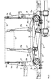
- a conventional stacker with a stack-conveying roller track is indicated, as a whole, at 1.
- the stacker in- dudes a conventional (not shown) swing plate, a bottom truck fork (not shown), a raking roller board 4 and a conveying roller track 5.
- the stacking shaft is referred to as 6, while the pressing station is marked 7 and the cylinder-pressing ram units are marked 8.
- the framework supporting stacker 1 is referred to generically with 9.
- the device according to the invention comprises, essentially, a storage box 10 housing the endboards 11 which are to be placed at the ends of the stacks marked 12.
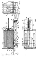
- Said storage box 10 is designed as an integral part of framework 9 of stacker 1 and consists of a mobile wall 13 and a guiding or shaped wall 14 placed opposite said mobile wall 13, the lower portion of which is provided with a slit 15 through which a respective endboard 11 is delivered.
- the bottom plate 16 of storage box 10 features a slot 17, produced in the median area of said bottom plate.
- Said storage box 10 is connected to a charging unit 18 of said endboards 11, comprising essentially a plate cursor 19 moving to-and-fro on the bottom of said storage box 10. Such motion is obtained by fixing the plate 19 to the mobile member 20 or outer cursor of a driving cylinder/ram unit 21, which is rigidly connected to the storage box 10 by means of end connectors marked 22.
- the cylinder/ram unit 21 is desirably conceived as a pneumatic so-called shaftless unit, namely of the type featuring an outer cursor shifted by means of an inner magnetic cursor, which is in turn shifted by the compressed air used to operate the unit.
- shaftless unit namely of the type featuring an outer cursor shifted by means of an inner magnetic cursor, which is in turn shifted by the compressed air used to operate the unit.
- Screws connecting the plate cursor 19 to said outer cursor 20 are marked 24.
- Said outer cursor is provided with suitable members 25 designed to vary the position of the above outer cursor 20 with respect to the cylinder/ram unit 21, so that strokes of varying lengths may be obtained with plate cursor 19, depending on the size of the endboards 11, while using one and the same cylinder-ram unit 21.
- Said stroke-varying members 25 comprise, in this particular instance, a threaded bar 26 carrying at one end a control wheel 27, the ends of said freely-revolving though axially stationary bar 26 being supported by plates 28 and 29 respectively, one such plate (28) being fixed to the bottom wall 16 of the storage box 10 and the other (29) to the aforementioned outer cursor 20.
- the plate 29 is furthermore connected with a casing 30, which may consist of two portions as in this illustration, housing a stationary core 31 acting as a nut screw, said threaded bar 26 running across said nut screw.
- the rotation of control wheel 27 results in the traverse of core 31, and, therefore, of the outer cursor 20 of the cylinder/ram unit 21, thus adjusting the stroke of said outer cursor 20 and, consequently, of the plate cursor 19.
- said plate cursor 19 is entirely removed from the storage box 10. In the latter position, said plate cursor causes the ejection of the endboard 11 from the storage box 10, endboard delivery being effected symmetrically with respect to the centre line B of the stacking shaft 6. Where the endboards 11 are smaller in size, said endboards shall be correctly positioned between the guiding front wall 14, comprising a raking upper sector 14a designed to pre-align said endboards, and the mobile rear wall 13.
- the latter is provided with a median projecting lug 32, designed to house the freely-revolving clear end of a threaded rod 33, which in turn engages a control wheel 34, the latter being free to rotate within a box-shaped casing 35 fixed to a stationary rear wall 36 of the storage box 10 and housing the aforementioned median nut-screw projecting lug 32.
- the rotation of control wheel 34 results, therefore, in the translation of the threaded rod 33, which in turn shifts the mobile wall 13.
- Both said mobile wall 13 and the stationary wall 36 feature in their lower portion a slit, 13a and 36a respectively, which defines a clearance for the passage of the plate cursor 19.
- number 37 refers to a supporting device specially designed to fix the storage box 10 to the framework 9 of the stacker 1, the possibility of transverse traversing of said storage box with respect to the stacker being provided.
- Said storage box is fixed to said framework by means of a screwed plate 38 housing a profiled bar 39 engaging, in this particular illustration, two brackets 40, which are designed as integral members of the bottom plate 16 of the storage box 10.
- the device according to the invention further comprises a stack-conveying slide 41, consisting essentially of a pod-mounted frame 42 resting, by means of tubular supports 43, on two supporting and sliding bars 44, which are fixed to the framework 9 of the stacker in a parallel position with respect to the raking roller board 4.
- Translation is effected by means of a chain drive 45 engaging two sprocket wheels 46 and 47, the former, 46, being supported as a freely-revolving member by a crosspiece 46a fixed to the ends of said supporting bars 44 and the latter, 47, being connected to a geared motor 48 and resting on the framework 9 of the stacker.
- Said chain 45 is linked, by means of a connecting plate 49, to a crosspiece 50 joining the two innermost tubular supports 43.
- the geared motor 48 may drive the slide 41 from the stacking shaft position 6, indicated in Fig. 2, to the opposite limit stop position, where the binding station 7 is located, as indicated in Fig. 2, and back.
- Two structurally similar side panels 51 are hinged onto said slide 41.
- Such hinging is effected by means of a shaft 52, two sprocket wheels, 53 and 54 respectively, being keyed onto the upper and lower portions thereof.
- the two upper wheels 53 and the two lower wheels 54 are connected by means of a respective crossed chain drive 55.
- the crossed chain drive engaging the upper wheels 53 comprises a crossed chain 55 and a cylinder ram driving unit 56.
- the operation of said unit 56 results, in the rotation of the side panels in the opening and closing directions respectively, as referred to with the continuous line and the dotted line in fig. 3.
- the side panels 51 are articulated, or adjustable, so as to enable signatures produced in varying sizes to be conveyed effectively, the dotted line referring to the position required for the proper conveyance of narrower signatures than the ones conveyed with the side panels standing in the position marked with the continuous line.
- Said articulations, marked 57 may be designed in any desired manner.
- the above consists of two transverse, parallel strips with two vertical strips 51c and 51d joining portions 51 b, as shown in Fig. 8.
- Stack completion is determined by kown means. This is followed by the closure of the hitherto open side panels 51, slide 41 being placed in the stacking- shaft position. Hence the stack is delivered and placed onto the conveyance roller track 5, the stack itself being supported laterally by said side panels 51. In its last downward conveyance section, the stack operates a photoelectric cell, which in turn operates the charging unit 18, whereby the plate cursor 19 is shifted into the storage box 10, resulting in the ejection of an endboard. As the stack reaches said roller track 5, it starts the conveyor motor 48, whereby the stack is conveyed into the binding station 7.
- a conveyance limit switch e.g.
- a microswitch is provided, whereby the pistons of the pressing cylinder/ram units 8 are lowered so as to reach a point where their respective ends rest against the endboard 11 placed at the top of the stack.
- the presence of the stack in the binding station is determined by a photoelectric cell, which readily drives the stacker truck fork back to its raised position: thus an endboard 11 has been placed onto said fork by the charging unit 18.
- the signatures are being placed onto the plate so as form the initial part of the stack.
- Side panels 51 are opened while the active ends of the pressing cylinder/ram units 8 are resting on the stack, which therefore will neither fall apart nor hollow out in any undesired way.
Landscapes
- Engineering & Computer Science (AREA)
- Mechanical Engineering (AREA)
- Pile Receivers (AREA)
- Forming Counted Batches (AREA)
- Specific Conveyance Elements (AREA)
- Basic Packing Technique (AREA)
Abstract
Description
- This invention relates to a device for providing signature stacks with endboards and for conveying said stacks in stackers for printing works and the like.
- Signature-stacking, as performed in printing works and the like by means of conventional stackers, normally requires that special boards be placed at the respective ends of the stacks once they are completed, the function of such boards being that of preventing the signatures placed at the ends of said stacks from suffering damage as may be caused by pressing rams and binding straps when tamping, or pressing, and binding said stacks. Such damage, in fact, normally results from the exceedingly high pressure exerted on the stacks - in the region of e.g. 600 kgs - during binding.
- Such boards are generally placed manually by an operator. While the incoming signatures are carried by the swing plate, the fork of the lift truck is raised to its uppermost position, hence a first board is placed by the operator, which thus becomes the bottom endboard. Then the swing plate is lowered and the formed part of the stack is placed onto said end- board, after which the plate is retracted and raised while more signatures are loaded onto the fork: the process is carried on until the desired stack height is achieved, at which point the operator places a second endboard at the top of the stack, namely, the top endboard. Hence the fork places the full stack onto the roller unit defining the bottom of the stack-forming shaft, which is designed to convey the stack toward the binding station. As the stack is placed on the bottom of the stacker, another manual operation must be performed, in that the operator must see to the effective conveyance of the stack from said stack-forming shaft to the binding station. The stack is supported by the roller bottom and rests against the stacker roller board. Conveyance is effected as follows: the operator places one hand onto the top endboard and with his other hand exerts pressure on the stack in order to drive it along the conveyance track. As the stack reaches the binding station, two rollers are lifted out of the roller board and pressed against the sides of the stack so as to keep it in the required position during pressing of same. These rollers, therefore, act as mobile side members. Pressing is normally effected by means of two adjacent vertical cylinder-ram units, whereas binding is carried out by means of a conventional skein-winder,employing e.g. thermoplastic straps.
- Where conventional stackers are employed, an operator is needed also in order to prevent the stack from hollowing out on one side and bulging on the other when the stack itself is being lowered (this defect is commonly referred to as a "banana- shaped stack" and is particularly likely to occur where the signatures are folded in-and-in); for otherwise the stack would most probably collapse as soon as it is left loose or placed onto the conveyor. In order to prevent this from happening, the operator places one hand onto the top of the stack and uses his free hand to correct any misalignment. Where conventional stackers are used, therefore, the operator must perform three functions, namely:
- 1. place the boards at the ends of the stacks;
- 2. check, and if necessary see, that the stacks are kept in the upright position after loading them onto the roller bottom of the stacker; and
- 3. push the stacks along the conveyance path leading from the stack-forming shaft to the binding station.
- The Italian patents No. 163186 and No. 163187 of the applicant relate to an automatic endboard- feeding device for endboards produced in just one size; these devices, however, require the use of two loaders and imply a considerable amount of circuitry. In addition, these loaders are designed to operate with endboards of a definite size, hence are unable to meet the varying operating requirements dictated by signatures of different sizes. These devices feature, furthermore, a stack-conveying device, which in turn implies considerable construction costs, besides depending for its operation on a definite signature size.
- Similar features are also disclosed in U.S.-A 4 554 867, published Nov 26, 1985, which discloses an apparatus for handling a stack of sheets comprising a first end-board hopper adjacent the row of lower rollers at the bottom of a stacking shaft and a second endboard hopper adjacent the top of the stack-binding workstation. It should be noted that endboard hoppers are typically large-sized devices, mounted at an overhead location above a stacker, and require period manual refilling. An operator typically must climb a ladder, peer into the hopper, determine the amount of endboards left, decide when to refill, and then fill the hopper with the correct number of endboards. In the case where several, e.g. ten, stackers are arranged side by side in a printing installation, the operator must move quickly and often between the stackers and refill the various hoppers at each stacker. The end- board hoppers disclosed in the U.S.-A 4 554 867 are further designed for feeding endboards of the same size, whereas it were highly desirable to feed with the same endboard hopper endboards with different sizes, that is according to the size of the respective stacks. U.S.-A 4 554 867 also teaches to use a slidable bracket supporting two rigid side plates for holding the stack during the displacing thereof from the stack shaft to the stack-binding workstation, whereby each side plate is swingable by a pair of pneumatic cylinder/ram units, a pair of link assemblies and a pair of rigid arms, so that a great number of element is required. With said rigid
swingable side plates 29 it is not possible to hold stacks of different width, because theside plates 29 will only be parallel to each other in only one single position, so that the side plates can only securely hold stacks of a predetermined fixed widt. - It is a major object of this invention to provide a device of the aforementioned type, which may be capable of performing the three functions referred to hereinabove in a fully automatic way, the device being based on a reasonably simple constructive concept and ensuring operational effectiveness. A further object of this invention is to provide a device of the aforementioned type, which may be operated as a fully automatic universal device, namely one which may be used for signatures produced in any given size.
- These as well as other objects are achieved, according to the invention, with a device for providing signature stacks with endboards and for conveying said stacks in stackers for printing works and the like with the features pointed out in the characterizing part of
claim 1. - According to the invention, the guiding wall of the endboard storage box is provided with a raking sector for sliding and positioning the endboards, while the middle portion of the mobile wall is provided with an outwardly projecting lug housing a freely-revolving though axially-fixed threaded rod designed to engage a control wheel, said wheel being supported in a freely-revolving though axially-fixed fashion in a box-like housing designed as an integral member of the stationary wall of the storage unit adjoining the mobile wall, and the housing in same the aforementioned projecting lug fitted in the middle portion of the mobile wall.
- In the device according to the invention, said members specially designed to vary the length of stroke of the mobile member of the endboard-delivering cylinder/ram unit consist, essentially, of a freely revolving though axially stationary threaded bar which is housed at one end in a plate supported by the bottom of the storage unit and, at the other end, in a plate designed as an integral member of said mobile part of the cylinder/ram unit, said threaded bar running across a core acting as a nut screw and fitted in a housing secured to said supporting plate and to said outer cursor member, said threaded bar being connected with a control wheel.
- According to the invention, the endboard storage unit is desirably provided with a rest whereby it may be fitted onto the stacker frame.
- Each of the side panels of the stack-conveying slide is advantageously provided with two arms set facing one another and carried by one and the same shaft, the top and bottom portions of which are provided with a sprocket wheel, the upper and lower sprocket wheels each driving a chain leading to a cylinder-ram driving unit, the upper cylinder/ram unit controlling the oscillation of the side panels in one direction and the lower cylinder/ram unit controlling the rotation of the side panels in the opposite direction, whereby said side panels may be opened and closed.
- Each of the side panels is equipped with a top arm and a bottom arm, which carry two crosspieces at right angles with respect to said arms.
- Moreover, each side panel is desirably articulated, hence the narrower stacks of signatures can be gripped with the portion thereof which is furthest from the supporting bars.
- According to the invention, two opposite pilot bars are fitted onto the casing of the stacker by means of rigid stands, and the slide conveyance members include a chain drive unit engaging two wheels, one of which is carried as a freely-rotating member by one of said pilot bar stands which are integral parts of the stacker casing, while the other is connected to a geared-motor unit, said chain being provided with a plate specially designed to secure the chain itself to a crosspiece which is integrally connected to said conveyance slide or trolley.
- With the device according to the invention, several important advantages are obtained. For one thing, the signature-stacking cycle is fully automated, which means that the work can be performed without the constant supervision of an operator, who may therefore be employed for different purposes. Secondly, once the device is installed onto the stacker, signature stacks in any desired size may be obtained, e.g. A4, A3, A5 single or double, magazine, tabloid, digest, double digest or any other commercial size. Signature size can be varied by simply adjusting the endboard charging unit as required - a simple operation, which can be effected quickly and without any difficulty. The device features an extremely small number of components, and the operating cycle may be fully automated by using relatively simple highly reliable circuits.
- A further advantage is that the device itself can be mounted onto any currently-employed stacker without difficulty, hence the whole stacking cycle may be automated even where conventional standing or raking stackers are used, with a conveyor track leading from the stacking shaft to the binding station.
- Further features, advantages, and details of the device according to the invention will become apparent from the following description of a preferred, though by no means restrictive, embodiment of the device, to be considered in conjunction with the hereto enclosed drawings.
- In said schematic drawings:
- Fig. 1 is a side elevational scrap view of a conventional signature stacker equipped with the device according to the invention;
- Fig. 2 is a front elevation of the stacker shown in Fig. 1;
- Fig. 3 is a plan view of the stack-conveying slide as formed by the stacker shown in Fig. 1;
- Fig. 4 is a longitudinal median section across the endboard storage box according to the invention, taken along line IV-IV in Fig. 1;
- Fig. 5 is a top view of the endboard storage box shown in Fig. 4;
- Fig. 6 is a side view of the endboard storage box according to Fig. 4;
- Fig. 7 is a front view of the stack-conveying slide and of the guides thereof, according to the arrow "A" shown in Fig. 1;
- Fig. 8 is a cross section taken along line VIII-VIII of Fig. 7.
- With reference to the above-listed Figures which relate to different scales and in which each member is identified through a specific reference number, a conventional stacker with a stack-conveying roller track is indicated, as a whole, at 1. The stacker in- dudes a conventional (not shown) swing plate, a bottom truck fork (not shown), a raking roller board 4 and a
conveying roller track 5. The stacking shaft is referred to as 6, while the pressing station is marked 7 and the cylinder-pressing ram units are marked 8. Theframework supporting stacker 1 is referred to generically with 9. The device according to the invention comprises, essentially, astorage box 10 housing theendboards 11 which are to be placed at the ends of the stacks marked 12. Saidstorage box 10 is designed as an integral part offramework 9 ofstacker 1 and consists of amobile wall 13 and a guiding orshaped wall 14 placed opposite saidmobile wall 13, the lower portion of which is provided with aslit 15 through which arespective endboard 11 is delivered. Thebottom plate 16 ofstorage box 10 features aslot 17, produced in the median area of said bottom plate. Saidstorage box 10 is connected to a chargingunit 18 of said endboards 11, comprising essentially aplate cursor 19 moving to-and-fro on the bottom of saidstorage box 10. Such motion is obtained by fixing theplate 19 to themobile member 20 or outer cursor of a driving cylinder/ram unit 21, which is rigidly connected to thestorage box 10 by means of end connectors marked 22. In order to reduce its overall dimensions, the cylinder/ram unit 21 is desirably conceived as a pneumatic so- called shaftless unit, namely of the type featuring an outer cursor shifted by means of an inner magnetic cursor, which is in turn shifted by the compressed air used to operate the unit. Such units are known already and, therefore, shall not be described in greater detail hereinafter. - Screws connecting the
plate cursor 19 to saidouter cursor 20 are marked 24. Said outer cursor is provided withsuitable members 25 designed to vary the position of the aboveouter cursor 20 with respect to the cylinder/ram unit 21, so that strokes of varying lengths may be obtained withplate cursor 19, depending on the size of the endboards 11, while using one and the same cylinder-ram unit 21. Said stroke-varyingmembers 25 comprise, in this particular instance, a threadedbar 26 carrying at one end acontrol wheel 27, the ends of said freely-revolving though axiallystationary bar 26 being supported byplates bottom wall 16 of thestorage box 10 and the other (29) to the aforementionedouter cursor 20. Theplate 29 is furthermore connected with acasing 30, which may consist of two portions as in this illustration, housing astationary core 31 acting as a nut screw, said threadedbar 26 running across said nut screw. The rotation ofcontrol wheel 27 results in the traverse ofcore 31, and, therefore, of theouter cursor 20 of the cylinder/ram unit 21, thus adjusting the stroke of saidouter cursor 20 and, consequently, of theplate cursor 19. Thus, as is readily apparent from the drawing relating to theendboards 11 of the largest commercial size, when theplate cursor 19 is at rest (withouter cursor 20 in the position marked with dotted lines, Fig. 4), it is housed in thestorage box 10, while in its delivery stop position (withouter cursor 20 in the position shown in Fig. 4) saidplate cursor 19 is entirely removed from thestorage box 10. In the latter position, said plate cursor causes the ejection of the endboard 11 from thestorage box 10, endboard delivery being effected symmetrically with respect to the centre line B of the stackingshaft 6. Where the endboards 11 are smaller in size, said endboards shall be correctly positioned between the guidingfront wall 14, comprising a raking upper sector 14a designed to pre-align said endboards, and the mobilerear wall 13. In the example under consideration, the latter is provided with amedian projecting lug 32, designed to house the freely-revolving clear end of a threadedrod 33, which in turn engages acontrol wheel 34, the latter being free to rotate within a box-shapedcasing 35 fixed to a stationaryrear wall 36 of thestorage box 10 and housing the aforementioned median nut-screw projecting lug 32. The rotation ofcontrol wheel 34 results, therefore, in the translation of the threadedrod 33, which in turn shifts themobile wall 13. Both saidmobile wall 13 and thestationary wall 36 feature in their lower portion a slit, 13a and 36a respectively, which defines a clearance for the passage of theplate cursor 19. In Fig. 6,number 37 refers to a supporting device specially designed to fix thestorage box 10 to theframework 9 of thestacker 1, the possibility of transverse traversing of said storage box with respect to the stacker being provided. Said storage box is fixed to said framework by means of a screwedplate 38 housing a profiledbar 39 engaging, in this particular illustration, twobrackets 40, which are designed as integral members of thebottom plate 16 of thestorage box 10. The device according to the invention further comprises a stack-conveyingslide 41, consisting essentially of a pod-mountedframe 42 resting, by means oftubular supports 43, on two supporting and slidingbars 44, which are fixed to theframework 9 of the stacker in a parallel position with respect to the raking roller board 4. Translation is effected by means of achain drive 45 engaging twosprocket wheels crosspiece 46a fixed to the ends of said supportingbars 44 and the latter, 47, being connected to a gearedmotor 48 and resting on theframework 9 of the stacker.Said chain 45 is linked, by means of a connecting plate 49, to acrosspiece 50 joining the two innermost tubular supports 43. Thus, the gearedmotor 48 may drive theslide 41 from the stackingshaft position 6, indicated in Fig. 2, to the opposite limit stop position, where thebinding station 7 is located, as indicated in Fig. 2, and back. Two structurallysimilar side panels 51 are hinged onto saidslide 41. Such hinging is effected by means of ashaft 52, two sprocket wheels, 53 and 54 respectively, being keyed onto the upper and lower portions thereof. As shown in Fig. 3, the twoupper wheels 53 and the two lower wheels 54 are connected by means of a respective crossedchain drive 55. The crossed chain drive engaging theupper wheels 53 comprises a crossedchain 55 and a cylinderram driving unit 56. The operation of saidunit 56 results, in the rotation of the side panels in the opening and closing directions respectively, as referred to with the continuous line and the dotted line in fig. 3. Theside panels 51 are articulated, or adjustable, so as to enable signatures produced in varying sizes to be conveyed effectively, the dotted line referring to the position required for the proper conveyance of narrower signatures than the ones conveyed with the side panels standing in the position marked with the continuous line. Said articulations, marked 57, may be designed in any desired manner. In this particular example, are provided twoportions respective portions side panel 51. In the example herein referred to, the above consists of two transverse, parallel strips with twovertical strips 51d joining portions 51 b, as shown in Fig. 8. - After this description of the structure and mechanisms of the components defining the device according to the invention, let us briefly summarize the steps involved in the fully automated operating cycle of same.
- Stack completion is determined by kown means. This is followed by the closure of the hitherto
open side panels 51, slide 41 being placed in the stacking- shaft position. Hence the stack is delivered and placed onto theconveyance roller track 5, the stack itself being supported laterally by saidside panels 51. In its last downward conveyance section, the stack operates a photoelectric cell, which in turn operates the chargingunit 18, whereby theplate cursor 19 is shifted into thestorage box 10, resulting in the ejection of an endboard. As the stack reaches saidroller track 5, it starts theconveyor motor 48, whereby the stack is conveyed into thebinding station 7. A conveyance limit switch, e.g. a microswitch, is provided, whereby the pistons of the pressing cylinder/ram units 8 are lowered so as to reach a point where their respective ends rest against theendboard 11 placed at the top of the stack. In the meantime, the presence of the stack in the binding station is determined by a photoelectric cell, which readily drives the stacker truck fork back to its raised position: thus anendboard 11 has been placed onto said fork by the chargingunit 18. Meanwhile the signatures are being placed onto the plate so as form the initial part of the stack.Side panels 51 are opened while the active ends of the pressing cylinder/ram units 8 are resting on the stack, which therefore will neither fall apart nor hollow out in any undesired way. Thus slide 41 is driven back to the stacking shaft while the aforementioned side supporting rollers are lifted out of the roller board, said rollers offering sufficient mechanical strength during stack compression. Compression is followed by stack binding, after which said positioning rollers are replaced and the rams of the pressing unit 8 are retracted to their initial position. - This leads us back to the position described at the beginning of the operating cycle.
- No detailed description of the relevant circuits and control units is provided, as these are readily accessible and may be freely selected in accordance with the technician's specific requirements. From the above description, it is readily apparent that the device according to the invention is effective in achieving the objects and advantages referred to hereinabove. Operations which have hitherto been performed manually by an operator, can now be performed through a fully automatic cycle and, more specifically, through the use of a single charger, whereby stacks of signatures of all sizes can be produced. The side panels of the slide or trolley are both light and simple in construction, and are furthermore designed to supply a reaction thrust in the region of e.g. 8-10 kgs. The reaction thrust required in order to withstand the considerable pressure exerted during compression, e.g. 600 kgs, is provided by conventional rocking aligner rolls, their resistance ranging from 30 to 50 kgs. A limited number of components is required for the construction of the side panels and of the relevant supporting slide, said components being furthermore easy to manufacture and functionally reliable.
Claims (9)
Priority Applications (1)
| Application Number | Priority Date | Filing Date | Title |
|---|---|---|---|
| AT86111755T ATE51834T1 (en) | 1985-09-10 | 1986-08-25 | DEVICE FOR APPLYING END PLATES TO STACKS OF SHEET AND FOR TRANSPORTING THESE STACKS INTO STACKING DEVICES FOR PRINTING SHOPS AND THE LIKE. |
Applications Claiming Priority (2)
| Application Number | Priority Date | Filing Date | Title |
|---|---|---|---|
| IT22104/85A IT1185698B (en) | 1985-09-10 | 1985-09-10 | DEVICE FOR SUPPLYING TABLETS TO SIGNATURE PACKAGES AND FOR THE TRANSFER OF THESE PACKAGES IN STACKERS FOR TYPOGRAPHS AND SIMILAR |
| IT2210485 | 1985-09-10 |
Publications (2)
| Publication Number | Publication Date |
|---|---|
| EP0215341A1 EP0215341A1 (en) | 1987-03-25 |
| EP0215341B1 true EP0215341B1 (en) | 1990-04-11 |
Family
ID=11191552
Family Applications (1)
| Application Number | Title | Priority Date | Filing Date |
|---|---|---|---|
| EP86111755A Expired - Lifetime EP0215341B1 (en) | 1985-09-10 | 1986-08-25 | A device for providing signature stacks with endboards and for the conveyance of said stacks in stackers for printing works and the like |
Country Status (5)
| Country | Link |
|---|---|
| US (1) | US4772169A (en) |
| EP (1) | EP0215341B1 (en) |
| AT (1) | ATE51834T1 (en) |
| DE (1) | DE3670260D1 (en) |
| IT (1) | IT1185698B (en) |
Families Citing this family (11)
| Publication number | Priority date | Publication date | Assignee | Title |
|---|---|---|---|---|
| NL8701166A (en) * | 1987-05-14 | 1988-12-01 | Breda Backer Rueb Maschf | PACKAGING DEVICE WITH IMPROVED STOCK STATION. |
| IT1223446B (en) * | 1987-11-20 | 1990-09-19 | Civiemme Srl | RETENTION DEVICE AND PACK GUIDE FOR VERTICAL STACKERS OF SIGNATURES |
| IT1236921B (en) * | 1989-12-22 | 1993-04-26 | Civiemme Srl | AUTOMATIC VERTICAL STACKER FOR SIGNATURES. |
| NO901737L (en) * | 1990-04-19 | 1991-10-21 | Norlito Maskin As | PACKING MACHINE FOR LEAVES (STACK). |
| US5807064A (en) * | 1995-10-05 | 1998-09-15 | Baldwin Technology Corporation | Apparatus for continuously varying the position of an article carrying platform |
| US5617784A (en) * | 1995-10-05 | 1997-04-08 | Baldwin Technology Corporation | Apparatus for bundling, transporting, and feeding sheets |
| US6688215B1 (en) * | 2002-10-18 | 2004-02-10 | Illinois Tool Works, Inc. | Stacker with integral strapper and modular head assembly |
| US9856047B2 (en) * | 2011-02-22 | 2018-01-02 | Graphic Packaging International, Inc. | Carton decasing system |
| CN110203439A (en) * | 2019-06-10 | 2019-09-06 | 深圳市红标点科技有限公司 | A kind of book pressing mechanism for books binding apparatus |
| CN111301917A (en) * | 2020-03-09 | 2020-06-19 | 孙继成 | Automatic code scanning warehouse-in and warehouse-out equipment applied to sample card storage |
| CN112249397A (en) * | 2020-11-16 | 2021-01-22 | 双峰县众鑫鞋材有限公司 | Corrugated box production is with being convenient for bind packing apparatus |
Family Cites Families (8)
| Publication number | Priority date | Publication date | Assignee | Title |
|---|---|---|---|---|
| CA474084A (en) * | 1951-05-29 | Charles Rawson Frederick | Magazines or label boxes for labelling machines | |
| US2643619A (en) * | 1949-07-05 | 1953-06-30 | Wrigley W M Jun Co | Severing mechanism |
| US2699862A (en) * | 1951-05-03 | 1955-01-18 | Walter & Company Inc B | Article unstacking and feed mechanism |
| US2879636A (en) * | 1957-01-23 | 1959-03-31 | T W & C B Sheridan Co | Wrapper applying machine for newspapers |
| FR1316976A (en) * | 1962-03-07 | 1963-02-01 | Beasley French & Company Ltd | Apparatus for inserting marking elements between sheets or similar flat elements arranged in a stack |
| US3440796A (en) * | 1966-06-02 | 1969-04-29 | Harrison White Inc | Topwrap apparatus |
| DE3040353A1 (en) * | 1980-10-25 | 1982-05-27 | Karl und Johannes Fried GmbH & Co KG, 7012 Fellbach | Woodworking machine feed mechanism - comprises reciprocating actuator with toothed dog engaging with side of workpiece |
| US4554867A (en) * | 1984-03-19 | 1985-11-26 | Stobb, Inc. | Method and apparatus for handling a stack of sheets |
-
1985
- 1985-09-10 IT IT22104/85A patent/IT1185698B/en active
-
1986
- 1986-08-25 DE DE8686111755T patent/DE3670260D1/en not_active Expired - Fee Related
- 1986-08-25 AT AT86111755T patent/ATE51834T1/en not_active IP Right Cessation
- 1986-08-25 EP EP86111755A patent/EP0215341B1/en not_active Expired - Lifetime
- 1986-08-26 US US06/900,391 patent/US4772169A/en not_active Expired - Lifetime
Also Published As
| Publication number | Publication date |
|---|---|
| US4772169A (en) | 1988-09-20 |
| ATE51834T1 (en) | 1990-04-15 |
| IT1185698B (en) | 1987-11-12 |
| IT8522104A0 (en) | 1985-09-10 |
| DE3670260D1 (en) | 1990-05-17 |
| EP0215341A1 (en) | 1987-03-25 |
Similar Documents
| Publication | Publication Date | Title |
|---|---|---|
| US5096369A (en) | Pallet inspection and stacking apparatus | |
| CN110451023B (en) | Packaging apparatus and packaging method | |
| US4764074A (en) | Pallet loading apparatus | |
| EP0215341B1 (en) | A device for providing signature stacks with endboards and for the conveyance of said stacks in stackers for printing works and the like | |
| EP0067782B1 (en) | Ream skid discharge arrangement for continuous discharge sheeter and method | |
| DE3705169A1 (en) | METHOD AND DEVICE FOR PACKING PRINTED PRODUCTS | |
| AU705911B2 (en) | Forms stacker | |
| US5096372A (en) | Paper feeding/piling apparatus for sheet-fed press | |
| JP4523247B2 (en) | Apparatus for transporting a stack formed from printing papers arranged so as to stand adjacent to each other in a collating machine and placed on a placing table | |
| JP2530208Y2 (en) | Equipment for filling sheet blanks into containers | |
| US7828507B2 (en) | Stack turning apparatus with multiple drive means to straighten and eject stack from turntable | |
| CN109987279A (en) | A kind of extruded type stacking packaging machine | |
| CN112811198A (en) | Intelligent stacking and separating device | |
| US5213321A (en) | Hopper loader for transporting sheets in an edge-standing arrangement, and method therefor | |
| US5707204A (en) | Stacking apparatus | |
| JP2577922Y2 (en) | Stacker device | |
| US3433372A (en) | Sheet material palletizing apparatus | |
| US5171125A (en) | Sheet material handling apparatus and method having a pivotable hopper and bottom feeder | |
| CN115571593B (en) | Cigarette transporting and stacking device | |
| CN221234156U (en) | Conveying device for electronic product packaging | |
| CN217996057U (en) | Emulsification-balanced oil powder finished product stacking device | |
| CN221068623U (en) | Packing apparatus is collected to veneer | |
| CN111003440B (en) | Conveying equipment | |
| CN219193518U (en) | Automatic unstacking and conveying system for logistics goods | |
| JP3403769B2 (en) | Gas cylinder transfer device |
Legal Events
| Date | Code | Title | Description |
|---|---|---|---|
| PUAI | Public reference made under article 153(3) epc to a published international application that has entered the european phase |
Free format text: ORIGINAL CODE: 0009012 |
|
| AK | Designated contracting states |
Kind code of ref document: A1 Designated state(s): AT CH DE FR GB IT LI NL SE |
|
| 17P | Request for examination filed |
Effective date: 19870613 |
|
| 17Q | First examination report despatched |
Effective date: 19880603 |
|
| ITF | It: translation for a ep patent filed | ||
| GRAA | (expected) grant |
Free format text: ORIGINAL CODE: 0009210 |
|
| AK | Designated contracting states |
Kind code of ref document: B1 Designated state(s): AT CH DE FR GB IT LI NL SE |
|
| REF | Corresponds to: |
Ref document number: 51834 Country of ref document: AT Date of ref document: 19900415 Kind code of ref document: T |
|
| REF | Corresponds to: |
Ref document number: 3670260 Country of ref document: DE Date of ref document: 19900517 |
|
| ET | Fr: translation filed | ||
| PLBE | No opposition filed within time limit |
Free format text: ORIGINAL CODE: 0009261 |
|
| STAA | Information on the status of an ep patent application or granted ep patent |
Free format text: STATUS: NO OPPOSITION FILED WITHIN TIME LIMIT |
|
| 26N | No opposition filed | ||
| ITTA | It: last paid annual fee | ||
| EAL | Se: european patent in force in sweden |
Ref document number: 86111755.4 |
|
| REG | Reference to a national code |
Ref country code: GB Ref legal event code: IF02 |
|
| PGFP | Annual fee paid to national office [announced via postgrant information from national office to epo] |
Ref country code: GB Payment date: 20020722 Year of fee payment: 17 |
|
| PGFP | Annual fee paid to national office [announced via postgrant information from national office to epo] |
Ref country code: AT Payment date: 20020819 Year of fee payment: 17 |
|
| PGFP | Annual fee paid to national office [announced via postgrant information from national office to epo] |
Ref country code: SE Payment date: 20020820 Year of fee payment: 17 Ref country code: NL Payment date: 20020820 Year of fee payment: 17 Ref country code: FR Payment date: 20020820 Year of fee payment: 17 |
|
| PGFP | Annual fee paid to national office [announced via postgrant information from national office to epo] |
Ref country code: CH Payment date: 20020903 Year of fee payment: 17 |
|
| PGFP | Annual fee paid to national office [announced via postgrant information from national office to epo] |
Ref country code: DE Payment date: 20020905 Year of fee payment: 17 |
|
| PG25 | Lapsed in a contracting state [announced via postgrant information from national office to epo] |
Ref country code: GB Free format text: LAPSE BECAUSE OF NON-PAYMENT OF DUE FEES Effective date: 20030825 Ref country code: AT Free format text: LAPSE BECAUSE OF NON-PAYMENT OF DUE FEES Effective date: 20030825 |
|
| PG25 | Lapsed in a contracting state [announced via postgrant information from national office to epo] |
Ref country code: SE Free format text: LAPSE BECAUSE OF NON-PAYMENT OF DUE FEES Effective date: 20030826 |
|
| PG25 | Lapsed in a contracting state [announced via postgrant information from national office to epo] |
Ref country code: LI Free format text: LAPSE BECAUSE OF NON-PAYMENT OF DUE FEES Effective date: 20030831 Ref country code: CH Free format text: LAPSE BECAUSE OF NON-PAYMENT OF DUE FEES Effective date: 20030831 |
|
| PG25 | Lapsed in a contracting state [announced via postgrant information from national office to epo] |
Ref country code: NL Free format text: LAPSE BECAUSE OF NON-PAYMENT OF DUE FEES Effective date: 20040301 |
|
| PG25 | Lapsed in a contracting state [announced via postgrant information from national office to epo] |
Ref country code: DE Free format text: LAPSE BECAUSE OF NON-PAYMENT OF DUE FEES Effective date: 20040302 |
|
| EUG | Se: european patent has lapsed | ||
| GBPC | Gb: european patent ceased through non-payment of renewal fee | ||
| REG | Reference to a national code |
Ref country code: CH Ref legal event code: PL |
|
| PG25 | Lapsed in a contracting state [announced via postgrant information from national office to epo] |
Ref country code: FR Free format text: LAPSE BECAUSE OF NON-PAYMENT OF DUE FEES Effective date: 20040430 |
|
| NLV4 | Nl: lapsed or anulled due to non-payment of the annual fee |
Effective date: 20040301 |
|
| REG | Reference to a national code |
Ref country code: FR Ref legal event code: ST |
|
| PG25 | Lapsed in a contracting state [announced via postgrant information from national office to epo] |
Ref country code: IT Free format text: LAPSE BECAUSE OF NON-PAYMENT OF DUE FEES Effective date: 20050825 |