EP0215286B1 - High power pulse transformer for short high-voltage and/or high-current pulses - Google Patents
High power pulse transformer for short high-voltage and/or high-current pulses Download PDFInfo
- Publication number
- EP0215286B1 EP0215286B1 EP86111083A EP86111083A EP0215286B1 EP 0215286 B1 EP0215286 B1 EP 0215286B1 EP 86111083 A EP86111083 A EP 86111083A EP 86111083 A EP86111083 A EP 86111083A EP 0215286 B1 EP0215286 B1 EP 0215286B1
- Authority
- EP
- European Patent Office
- Prior art keywords
- winding
- power pulse
- pulse transformer
- windings
- core
- Prior art date
- Legal status (The legal status is an assumption and is not a legal conclusion. Google has not performed a legal analysis and makes no representation as to the accuracy of the status listed.)
- Expired - Lifetime
Links
Images


Classifications
-
- H—ELECTRICITY
- H01—ELECTRIC ELEMENTS
- H01S—DEVICES USING THE PROCESS OF LIGHT AMPLIFICATION BY STIMULATED EMISSION OF RADIATION [LASER] TO AMPLIFY OR GENERATE LIGHT; DEVICES USING STIMULATED EMISSION OF ELECTROMAGNETIC RADIATION IN WAVE RANGES OTHER THAN OPTICAL
- H01S3/00—Lasers, i.e. devices using stimulated emission of electromagnetic radiation in the infrared, visible or ultraviolet wave range
- H01S3/09—Processes or apparatus for excitation, e.g. pumping
- H01S3/097—Processes or apparatus for excitation, e.g. pumping by gas discharge of a gas laser
- H01S3/0971—Processes or apparatus for excitation, e.g. pumping by gas discharge of a gas laser transversely excited
- H01S3/09713—Processes or apparatus for excitation, e.g. pumping by gas discharge of a gas laser transversely excited with auxiliary ionisation, e.g. double discharge excitation
-
- H—ELECTRICITY
- H01—ELECTRIC ELEMENTS
- H01F—MAGNETS; INDUCTANCES; TRANSFORMERS; SELECTION OF MATERIALS FOR THEIR MAGNETIC PROPERTIES
- H01F30/00—Fixed transformers not covered by group H01F19/00
- H01F30/06—Fixed transformers not covered by group H01F19/00 characterised by the structure
- H01F30/10—Single-phase transformers
Abstract
Description
Die Erfindung bezieht sich auf einen Hochleistungs-Impulsübertrager für kurze Impulse hoher Spannung und/oder hoher Ströme, vorzugsweise für Schaltkreise von Hochleistungslasern, gemäß Oberbegriff des Anspruchs 1.The invention relates to a high-power pulse transmitter for short pulses of high voltage and / or high currents, preferably for circuits of high-power lasers.
Ein solcher Hochleistungs-Impulsübertrager ist durch (1) - siehe anliegendes Literaturverzeichnis - bekannt. Bevor darauf näher eingegangen wird, zunächst einige Ausführungen grundsätzlicher Art.Such a high-performance pulse transmitter is known from (1) - see attached bibliography. Before going into this in more detail, a few basic statements.
Bei direkter Kopplung gelingt es in der Hochleistungsimpulstechnik häufig nicht, den Widerstand der Last an den charakteristischen Widerstand eines pulserzeugenden Netzwerkes anzupassen. Häufig mangelt es auch an Schaltelementen, welche die von der Anwendung her vorgegebenen Spannungen und Ströme zu schalten vermögen.With direct coupling, it is often not possible in high-performance pulse technology to adapt the resistance of the load to the characteristic resistance of a pulse-generating network. Often there is also a lack of switching elements that can switch the voltages and currents specified by the application.
Eine Möglichkeit, diese technischen Einschränkungen zu umgehen, bietet der Einsatz von Hochleistungs-Impulsübertragern, auch vereinfachend als Pulstransformatoren bezeichnet. Ihre möglichen Aufgaben sind u.a.: Stromanpassung, Spannungsanpassung, Impedanzanpassung, Potentialtrennung und Potentialumkehr.One way of circumventing these technical restrictions is to use high-performance pulse transformers, also referred to simply as pulse transformers. Your possible tasks include: current adjustment, voltage adjustment, impedance adjustment, electrical isolation and potential reversal.
Einige Anwendungsfälle seien im Folgenden näher erläutert: Bei der Aufladung eines pulserzeugenden Netzwerkes mit Flüssigdielektrikum, wie es z.B. bei Hochleistungspulslasern eingesetzt wird - vergleiche dazu EP-A1-0,024,576, insbesondere Fig. 11 (2) - brächte es technische Vorteile, die Aufladung aus einem thyristorgeschalteten Netzteil vorzunehmen. Thyristoren schalten verhältnismäßig hohe Ströme bei niedrigen Haltespannungen. Das pulserzeugende Netzwerk soll im psec-Bereich auf Spannungen von mehreren 10 kV aufgeladen werden.Some applications are explained in more detail below: When charging a pulse-generating network with a liquid dielectric, such as If high-power pulse lasers are used - compare EP-A1-0,024,576, in particular Fig. 11 (2) - there would be technical advantages in charging from a thyristor-connected power supply. Thyristors switch relatively high currents at low withstand voltages. The pulse-generating network is to be charged to voltages of several 10 kV in the psec range.
Zur Anpassung der niedrigen Spannung im Thyristorkreis an die erforderliche hohe Spannung im pulserzeugenden Netzwerk kann ein Resonanztransformator eingesetzt werden, wie z.B. in (3) beschrieben. In diesem speziellen Fall beträgt indessen die Aufladezeit des pulserzeugenden Netzwerks mehrere Millisekunden. Um eine Aufladung in wenigen psec zu erreichen, muß ein pulsübertrager eingesetzt werden, dessen Streuinduktivität auf ein Mindestmaß reduziert ist.A resonance transformer can be used to adapt the low voltage in the thyristor circuit to the required high voltage in the pulse-generating network, e.g. described in (3). In this special case, however, the charging time of the pulse generating network is several milliseconds. To achieve a charge in a few psec, a pulse transformer must be used, the leakage inductance of which is reduced to a minimum.
Mit herkömmlichen Hochspannungstransformatoren lassen sich wegen ihrer bauartbedingten hohen Streuinduktivitäten die geforderten Energien in der kurzen Zeit nicht übertragen. Ein weiteres Erfordernis ist, den Übertrager bei hohen Wiederholraten, auch unter der Abkürzung PRR (= pulse repetition rate) bekannt, betreiben zu können. Es stellt sich dann das Problem, in der notwendigerweise kompakten Anordnung die Verlustwärme effektiv abzuführen.With conventional high-voltage transformers, the required energies cannot be transmitted in a short time due to their high leakage inductances. Another requirement is to be able to operate the transformer at high repetition rates, also known under the abbreviation PRR (= pulse repetition rate). The problem then arises of effectively dissipating the heat loss in the necessarily compact arrangement.
Zur Problematik und zum Anwendungsbereich von gattungsgemäßen Hochleistungs-Impulsübertragern muß auch auf die Versorgung einer Röntgenblitzröhre zur Erzeugung von Röntgenimpulsen im Submikrosekundenbereich hoher Intensität, insbesondere auch bei hohen Wiederholraten, verwiesen werden. Bei der Ansteuerschaltung der Röntgenblitzröhre können das pulserzeugende Netzwerk und das Schaltelement auf die erforderliche Beschleunigungsspannung der Röntgenröhre ausgelegt sein, vergleiche (4), (5) und (6). Der Nachteil dieser bekannten Anordnungen liegt in der notwendigen hohen Spannungsfestigkeit der Bauelemente, die insbesondere bei hohen Wiederholraten hohe technologische Schwierigkeiten mit sich bringt.Regarding the problems and the area of application of generic high-performance pulse transmitters, reference must also be made to the supply of an X-ray flash tube for generating X-ray pulses in the submicrosecond range of high intensity, in particular also at high repetition rates. In the control circuit of the X-ray flash tube, the pulse-generating network and the switching element can be designed for the required acceleration voltage of the X-ray tube, compare (4), (5) and (6). The disadvantage of these known arrangements lies in the necessary high dielectric strength of the components, which brings with it high technological difficulties, particularly at high repetition rates.
Eine weitere Möglichkeit, eine Röntgenröhre anzusteuern, besteht darin, den Versorgungsimpuls für die Röntgenröhre an der Sekundärseite eines Pulsübertragers abzugreifen. Ausführungen dazu finden sich in (4) und (7). Schwierigkeiten treten bei dieser Methode dann auf, wenn möglichst hohe Energien in möglichst kurzer Zeit übertragen werden sollen. Zur Erhöhung der Grenzfrequenz eines Übertragers für derart hohe Spannungen bei gleichzeitig niedrigem Innenwiderstand muß eine sehr enge Kopplung zur Reduzierung des inneren Spannungsabfalles angestrebt werden, bei gleichzeitig kleinstmöglicher Streuinduktivität. Die dazu erforderliche Minimierung der Isolationsabstände zwischen Sekundär- und Primärwicklung sowie zwischen dem Kern und den Wicklungen führt wegen der hohen Spannungen zu extrem hohen elektrischen Feldstärken.Another option for controlling an X-ray tube is to tap the supply pulse for the X-ray tube on the secondary side of a pulse transmitter. Information on this can be found in (4) and (7). Difficulties arise with this method if the highest possible energies are to be transferred in the shortest possible time. In order to increase the cut-off frequency of a transformer for such high voltages with a low internal resistance, a very close coupling to reduce the internal voltage drop must be sought, with the smallest possible leakage inductance. The necessary minimization of the insulation distances between the secondary and primary windings and between the core and the windings leads to extremely high electrical field strengths due to the high voltages.
Der gattungsgemäße Hochleistungs-Impulsübertrager nach (1), von dem die Erfindung ausgeht, weist zwar schon die gewünschte kurze Pulsdauer auf, es ist jedoch zu verzeichnen, daß schon bei relativ hohen Lastwiderständen das Übetragungsverhältnis, bezogen auf das Leerlaufübersetzungsverhältnis, beträchtlich abfällt. Weitere technische Nachteile dieses bekannten Impulsübertragers ergeben sich insbesondere bei höheren Spannungen und vor allem im Dauerbetrieb. Bei den notwendigerweise sehr hohen elektrischen Feldstärken treten bei den Pulsen kurzer Anstiegszeit auch in sorgfältig ausgewählten und verarbeiteten festen Dielektrika Koronaeffekte auf, die eine irreparable Zerstörung des Dielektrikums zur Folge haben und damit zum Ausfall des Übertragers führen können. Bei hohen Wiederholraten und hohen mittleren Leistungen würde ein festes Dielektrikum ferner die Abfuhr unvermeidlicher Verlustwärme aus dem weichmagnetischen Kern technisch außerordentlich erschweren.The generic high-performance pulse transformer according to (1), from which the invention is based, already has the desired short pulse duration, but it can be seen that even at relatively high load resistances, the transmission ratio, based on the idle ratio, drops considerably. Further technical disadvantages of this known pulse transmitter arise in particular at higher voltages and especially in continuous operation. Given the necessarily very high electric field strengths, corona effects also occur in carefully selected and processed solid dielectrics with the pulses of short rise time, which irreparably destroy the dielectric and can therefore lead to the failure of the transmitter. At high repetition rates and high average powers, a solid dielectric would also make the removal of inevitable heat loss from the soft magnetic core extremely difficult.
Die der Erfindung zugrunde liegende allgemeine Aufgabe besteht darin, die beim gattungsgemäßen Hochleistungs-Impulsübertrager nach (1) auftretenden Schwierigkeiten zu meistern, wobei die Streuinduktivität noch weiter als beim Bekannten reduziert, die Koronaeffekte vermieden bzw. die Spannungsfestigkeit gesteigert sowie die Abfuhr der Verlustwärme verbessert werden sollen.The general object on which the invention is based is to overcome the difficulties encountered in the generic high-performance pulse transformer according to (1), the leakage inductance being reduced even further than that known, the corona effects avoided or the dielectric strength increased and the dissipation of the heat loss improved should.
Diese allgemeine Aufgabenstellung gilt auch in bezug auf einen weiteren bekannten Impulsübertrager nach (8), welcher aus einer Anordnung gestapelter blattförmiger Windungen mit Dielektrikum-Zwischenlagen besteht. Auch hier ergibt sich das Problem der Spannungsfestigkeit, weil an den Kanten der blattförmigen Leiter auftretende elektrische Feldstärken bei längerem Betrieb zwangsläufig zur baldigen Zerstörung aufgrund von Koronaeffekten führen. Die Trennflächen zwischen dem festen Dielektrikum und den Leitern werden außerdem durch die Stromkräfte erheblich mechanisch beansprucht, so daß auch dadurch elektrische Durchschläge begünstigt werden. Deshalb kann die an sich verhältnismäßig niedrige Streuinduktivität nicht ausgenutzt werden; die elektrische Isolaton ist zu störanfällig.This general task also applies to another known pulse transformer according to (8), which consists of an arrangement of stacked sheet-like turns with dielectric intermediate layers. Again there is the problem of dielectric strength because of the edges of the sheet electrical field strengths occurring in the case of prolonged operation inevitably lead to soon destruction due to corona effects. The separating surfaces between the solid dielectric and the conductors are also subjected to considerable mechanical stresses by the current forces, so that electrical breakdowns are also promoted thereby. Therefore, the relatively low leakage inductance cannot be exploited; the electrical isolation is too susceptible to faults.
Nach Vorstehendem liegt der Erfindung die spezielle Aufgabe zugrunde, einen gattungsgemäßen Hochleistungs-Impulsübertrager für kurze Impulse hoher Spannung und/oder hoher Ströme zu schaffen, welcher über die allgemeine Aufgabenstellung hinausAccording to the above, the invention is based on the special task of creating a generic high-performance pulse transformer for short pulses of high voltage and / or high currents, which goes beyond the general task
zur Stromanpassung, Spannungsanpassung, Impedanzanpassung, Potentialtrennung und Potentialumkehr einsetzbar ist, d.h. insbesondere auch als sogenannter "Step-up"-Transformator zur Erzeugung von Impulsen höherer Spannung bei optimaler Leistungsübertragung, aber auch als sogenannter Stepdown-Transformator zur Erzeugung von kurzen Impulsen sehrhoher Stromstärke, wobei Hochspannungsimpulse heruntertransformiert und in eine sehr niederohmige Last eingespeist werden. Während bei den Step-up-Transformatoren die Eisenverluste die Kupferverluste überwiegen, müssen hingegen bei den Step-down-(Strom-)Transformatoren die Verluste in den Leitern niedrig gehalten werden durch Optimierung der Wicklungsquerschnitte;can be used for current adaptation, voltage adaptation, impedance adaptation, electrical isolation and potential reversal, i.e. in particular also as a so-called "step-up" transformer for generating pulses of higher voltage with optimal power transmission, but also as a so-called step-down transformer for generating short pulses of very high amperage, high-voltage pulses being transformed down and fed into a very low-impedance load. While the iron losses outweigh the copper losses in the step-up transformers, the losses in the conductors in the step-down (current) transformers must be kept low by optimizing the winding cross-sections;
zur Versorgung einer Röntgenblitzröhre zur Erzeugung von Röntgenimpulsen im Submikrosekundenbereich hoher Intensität, und insbesondere auch bei hohen Wiederholraten, geeignet ist;is suitable for supplying an X-ray flash tube for generating X-ray pulses in the submicrosecond range of high intensity, and in particular also at high repetition rates;
im Betrieb als Step-up-Transformator, insbesondere zur Ansteuerung einer Röntgenblitzröhre, eine ausreichend hohe Grenzfrequenz bei gleichzeitig niedrigem Innenwiderstand und eine sehr enge Kopplung von Unter- und Oberspannungswicklung aufweist, bei gleichzeitig kleinstmöglicher Streuinduktivität.in operation as a step-up transformer, in particular for controlling an X-ray flash tube, has a sufficiently high cut-off frequency with low internal resistance and a very close coupling of low and high voltage winding, with the smallest possible leakage inductance.
Ausgehend von einem Hochleistungs-Impulsübertrager für kurze Impulse hoher Spannung und/oder hoher Ströme gemäß Oberbegriff des Anspruchs 1 wird die der Erfindung zugrundeliegende Aufgabe durch die im Kennzeichen des Anspruchs 1 angegebenen Merkmale gelöst. Vorteilhafte Weiterbildungen sind in den Unteransprüchen 2 bis 10 angegeben.Starting from a high-performance pulse transmitter for short pulses of high voltage and / or high currents according to the preamble of claim 1, the object on which the invention is based is achieved by the features specified in the characterizing part of claim 1. Advantageous further developments are specified in
Die mit der Erfindung erzielbaren Vorteile sind vor allem darin zu sehen, daß die Probleme der Spannungsfestigkeit und des Abtransports der Verlustwärme bei Hochleistungs-Impulsübertragern nun grundsätzlich gelöst sind. Der Erfindungsgegenstand zeichnet sich durch die folgenden Merkmale aus:
- 1) Hohe Spannungsfestigkeit,
- 2) extrem enge Kopplung,
- 3) geringe Streuinduktivität und hohe Grenzfrequenz,
- 4) geringer Wicklungswiderstand und hohe Stromamplituden,
- 5) problemloses Abführen der Verlustwärme,
- 6) hohe Zuverlässigkeit und hohe Lebensdauer.
- 1) High dielectric strength,
- 2) extremely tight coupling,
- 3) low leakage inductance and high cut-off frequency,
- 4) low winding resistance and high current amplitudes,
- 5) easy dissipation of the heat loss,
- 6) high reliability and long life.
Zur Erzielung dieser günstigen Eigenschaften trägt im besonderen Maße bei, daß insbesondere an Orten hoher elektrischer Feldstärke auf jegliche Isolation aus festem Dielektrikum verzichtet wird. Alle Wicklungen haben selbsttragende bzw. freitragende Strukturen; darunter wird verstanden, daß die einzelnen Windungen der Ober- und Unterspannungswicklung aufgrund geeigneten Querschnitts hinreichend steife oder starre Spiralen aufweisen, welche - ohne untereinander oder am Kern abgestützt zu sein - ihre Form beibehalten und welche lediglich an Anschlußenden der kleinsten Wicklungseinheiten an den Stützisolatoren festgelegt bzw. "gefangen" sind. Die Isolation bildet eine dielektrische Flüssigkeit. Geeignet dazu sind Transformatoröl oder fluorierter Kohlenwasserstoff. In diese Flüssigkeit tauchen die Wicklungen und der Magnetkern - jeweils von separaten Haltestrukturen getragen - ein. Die dielektrische bzw. Isolierflüssigkeit ermöglicht einen problemlosen Abtransport der Verlustwärme aus dem Magnetkern, dem Dielektrikum selbst und den Wicklungen, z.B. durch Eigenkonvektion oder durch Zwangsumwälzung in einem mit einem Wärmetauscher versehenen geschlossenen Kreislauf. Es lassen sich nun hohe Spannungen bei gleichzeitig kompakten Aufbau wegen der hohen Isolationsfestigkeit der dielektrischen Flüssigkeit technisch problemlos erreichen. Koronabildung wird vermieden, da die Flüssigkeit die blanken oder allenfalls eine dünne Oxydhaut oder Schutzlackschicht aufweisenden Leiter ausreichend gut benetzt. Sollte sich dennoch ein Spannungsüberschlag im Übertrager ereignen, so verhält sich das flüssige Dielektrikum selbstheilend. Der freitragende Aufbau erleichtert eine bifilare Anordnung von Primär- und Sekundärwicklung (Unter- und Oberspannungswicklung), eine Voraussetzung für geringstmögliche Streuinduktivität. Als Kernmaterial für die Übertrager kommen z.B. Ferrite in Frage. Durch die Verwendung von sogenannten metallischen Gläsern, vergleiche dazu (9), lassen sich aufgrund der höheren Sättigungsinduktion dieser Materialien noch kompaktere Übertrager für noch höhere Spannungen aufbauen.In order to achieve these favorable properties, it is particularly beneficial that any insulation made of solid dielectric is dispensed with, particularly in places with a high electric field strength. All windings have self-supporting or self-supporting structures; this means that the individual windings of the high and low voltage windings have sufficiently stiff or rigid spirals due to a suitable cross section, which - without being supported one below the other or at the core - retain their shape and which are fixed or attached to the support insulators only at the connecting ends of the smallest winding units are "caught". The insulation forms a dielectric liquid. Transformer oil or fluorinated hydrocarbon are suitable for this. The windings and the magnetic core - each supported by separate holding structures - are immersed in this liquid. The dielectric or insulating liquid enables problem-free removal of the heat loss from the magnetic core, the dielectric itself and the windings, e.g. by self-convection or by forced circulation in a closed circuit provided with a heat exchanger. It is now technically easy to achieve high voltages with a compact structure due to the high insulation strength of the dielectric liquid. Corona formation is avoided because the liquid wets the bare conductors or, if need be, a thin oxide skin or protective lacquer layer, sufficiently well. Should a voltage flashover nevertheless occur in the transformer, the liquid dielectric behaves self-healing. The self-supporting structure facilitates a bifilar arrangement of primary and secondary windings (low and high voltage windings), a prerequisite for the lowest possible leakage inductance. The core material for the transformers is e.g. Ferrites in question. By using so-called metallic glasses, compare (9), due to the higher saturation induction of these materials, even more compact transformers can be built for even higher voltages.
Im folgenden wird anhand der Zeichnung, in welcher fünf Ausführungsbeispiele der Erfindung dargestellt sind, diese noch näher erläutert. Darin zeigt in vereinfachter, zum Teil schematischer Darstellung:
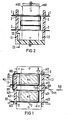
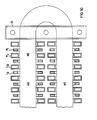
- Fig. 1 ein erstes einfaches Ausführungsbeispiel für einen Hochleistungs-Impulsübertrager (im folgenden abgekürzt als Impulsübertrager bezeichnet) nach der Erfindung in einem Grundrißschnitt durch den Magnetkern und die Stützisolatoren nach der Linie I-I aus Fig. 2;
- Fig. 2 den Gegenstand nach Fig. 1 im Aufriß;
- Fig. 3 eine Seitenansicht des Impulsübertragers nach Fig. 1 und Fig. 2, zum Teil im Schnitt nach der Linie III―III aus Fig.2 (ein Stützisolator entfernt);
- Fig. 4 ein zweites Ausführungsbeispiel, stark vereinfacht, wobei nur Magnetkern und einige kleinste Wicklungseinheiten dargestellt sind. Ein Schenkel des Trafokerns ist hier mit drei kleinsten Wicklungseinheiten bestückt, die ober- bzw. unterspannungsseitig jeweils zwei Windungen umfassen;
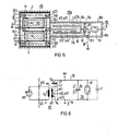
- Fig. 5 den Impulsübertrager nach Fig. 1, zusammengebaut mit der räumlichen Anordnung eines pulserzeugenden Netzwerkes in Blümlein-Schaltung mit einem Thyratron als Hochspannungsschalter, wobei an die Sekundärseite des Impulsübertrages eine Röntgenblitzröhre angeschlossen werden kann;
- Fig. 6 das Schaltschema für die Anordnung nach Fig. 5, ergänzt durch eine an die Sekundärseite des Impulsübertragers angeschlossene Röntgenblitzröhre, wobei alternativ zum Thyratron eine Funkenstrecke als schneller Hochspannungsschalter gestrichelt angedeutet ist;
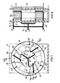
- Fig. 7 ein drittes Ausführungsbeispiel mit einem Ringkern-Impulsübertrager im Aufriß in einer der Fig. 3 entsprechenden Darstellung;
- Fig. 8 den Schnitt längs der Linie VIII―VIII aus Fig. 7;
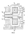
- Fig. 9 ein fünftes Ausführungsbeispiel mit einem als Strom-(Step-down-)Transformator ausgebildeten Impulsübertrager in einer der Darstellungsweise der Figuren 1 und 8 entsprechenden Grundriß-Schnittdarstellung und
- Fig. 10 einen Teilschnitt nach der Linie X-X aus Fig. 9, aus welchem der Grundriß des ovalen Magnetkerns und der Querschnitt der Wicklungsleiter erkennbar sind.
- Figure 1 shows a first simple embodiment of a high-performance pulse transmitter (hereinafter referred to as pulse transmitter) according to the invention in a plan view through the magnetic core and the post insulators according to line II of Fig. 2.
- Fig. 2 shows the object of Figure 1 in elevation.
- 3 shows a side view of the pulse transmitter according to FIGS. 1 and 2, partly in section along the line III ― III from FIG. 2 (a post insulator removed);
- Fig. 4 shows a second embodiment, greatly simplified, only magnetic core and some smallest winding units are shown. One leg of the transformer core is equipped with three smallest winding units, each comprising two turns on the upper and lower voltage side;
- 5 shows the pulse transmitter according to FIG. 1, assembled with the spatial arrangement of a pulse-generating network in a Blümlein circuit with a thyratron as a high-voltage switch, an X-ray flash tube being able to be connected to the secondary side of the pulse transmission;
- FIG. 6 shows the circuit diagram for the arrangement according to FIG. 5, supplemented by an X-ray flash tube connected to the secondary side of the pulse transmitter, with a spark gap being indicated alternatively to the thyratron as a faster high-voltage switch;
- FIG. 7 shows a third exemplary embodiment with a toroidal core pulse transformer in elevation in a representation corresponding to FIG. 3;
- 8 shows the section along the line VIII ― VIII from Fig. 7.
- 9 shows a fifth exemplary embodiment with a pulse transformer designed as a current (step-down) transformer in a plan and sectional representation corresponding to the representation of FIGS. 1 and 8
- Fig. 10 is a partial section along the line XX of Fig. 9, from which the outline of the oval magnetic core and the cross section of the winding conductor can be seen.
In Fig. 1 bis Fig. 3 ist die freitragende Wicklung des Impulsübertragers als Ganzes mit W bezeichnet, die Primärwicklung mit w1, die Sekundärwicklung mit w2. Die Primärwicklung w1 ist identisch mit der Unterspannungswicklung, wenn die Primärspannung u, kleiner als die Sekundärspannung U2 ist, und in diesem Falle ist auch die Sekundärwicklung identisch mit der Oberspannungswicklung. Dies gilt für den sogenannten Spannungs- oder Step-up-Transformator, wogegen bei einem Strom-(Step-down) Transformator bei höherer Spannung ein niedriger Strom, welcher der primärwicklung zugeführt wird, auf einen sekundärseitig höheren Strom bei niedriger Spannung herauftransformiert wird. Im letzteren Falle ist die Primärspannung die Oberspannung und die Sekundärspannung die Unterspannung.1 to 3, the unsupported winding of the pulse transmitter is designated as a whole by W, the primary winding by w 1 , the secondary winding by w 2 . The primary winding w 1 is identical to the undervoltage winding if the primary voltage u is less than the secondary voltage U2 , and in this case the secondary winding is also identical to the high-voltage winding. This applies to the so-called voltage or step-up transformer, whereas in the case of a current (step-down) transformer at higher voltage, a lower current which is fed to the primary winding is transformed up to a higher current on the secondary side at low voltage. In the latter case, the primary voltage is the upper voltage and the secondary voltage is the undervoltage.
Die freitragenden Wicklungen W1, W2 erfordern, daß jeweils eine Haltestruktur, als Ganzes mit H bezeichnet, für den Magnetkern M1, für die Primärwicklung wl und die Sekundärwicklung W2 vorzusehen ist. Der Magnetkern M1, vorzugsweise ein Ferritkern, also aus hochpermeablem Material, ist als Rechteckkern ausgeführt, dessen vier in sich geschlossene Magnetschenkel m1, m2, m3, m4 um ein zentrales Fenster 5 herum angeordnet sind, s daß die beiden Breitseiten des Magnetkerns M1 (im folgenden abgekürzt als "Kern" bezeichnet) achsnormal zur Fensterachse 5.0 verlaufen.The self-supporting windings W 1 , W2 require that a holding structure, designated as a whole by H, be provided for the magnetic core M1, for the primary winding w 1 and for the secondary winding W 2 . The magnetic core M1, preferably a ferrite core, i.e. made of highly permeable material, is designed as a rectangular core, the four self-contained magnetic legs m1, m2, m3, m4 are arranged around a
Der Kern M1, d.h. in diesem Falle seine beiden Schenkel m2, m4, wird umschlungen von der schon erwähnten Wicklung W, wobei die Primärwicklung w1 und die Sekundärwicklung w2 jeweils mit dem Kern M1 und miteinander verkettet und die elektrisch isolierten, metallischen Leiter 11 und 12 für die Windungen wo, der Primär- und w02 der Sekundärwicklung w1, w2 weitgehend bifilar zueinander geführt sind. Primär-und Sekundärwicklung sind, wie weiter oben bereits ausgeführt, mit der Unter- und der Oberspannungswicklung bei einem Spannungstransformator identisch, welche im folgenden abgekürzt als O-Wicklung und als U-Wicklung bezeichnet werden. Unter bifilar wird hier wie im folgenden verstanden, daß die Strompfade der Wicklungsleiter 11, 12 bzw. Windungen w01, w02 derart eng benachbart und parallel zueinander verlaufen, daß die von in ihnen fließenden Strömen erzeugten magnetischen Streufelder sich weitestgehend aufheben.The core M1, ie in this case its two legs m2, m4, is wrapped in the winding W already mentioned, the primary winding w 1 and the secondary winding w 2 each being chained to the core M1 and to one another and the electrically insulated, metallic conductors 1 1 and 1 2 for the turns where, the primary and w 02 of the secondary winding w 1 , w 2 are largely bifilar. As already explained above, the primary and secondary windings are identical to the low and high voltage windings in the case of a voltage transformer, which are referred to below as the O winding and the U winding. Bifilar is understood here as follows that the current paths of the winding conductors 1 1 , 1 2 or windings w 01 , w 02 run so closely adjacent and parallel to one another that the magnetic stray fields generated by currents flowing in them largely cancel each other out.
Erfindungsgemäß weisen nun die bevorzugt aus einem gut leitfähigen Material mit einem spezifischen Widerstand von insbesondere
![]()
![]()
Was den Wärmeübergang von der Oberfläche der Primär- oder Sekundärwicklung auf das sie umspülende flüssige Dielektrikum angeht, so gilt allgemein nach Newton:![]()
- Q =Wärmemenge, die durch die Grenzfläche tritt, in Joule bzw. W·s,
- a = Wärmeübergangskoeffizient (siehe oben),
- A = Größe der Übergangsfläche in m2,
- t = Zeitdauer des Überganges in Sekunden,
- Δv =Temperaturdifferenz zwischen dem flüssigen Dielektrikum und der Oberfläche der Wicklung W1 bzw. W2 in K.
- Q = amount of heat that passes through the interface, in joules or Ws,
- a = heat transfer coefficient (see above),
- A = size of the transition area in m 2 ,
- t = duration of the transition in seconds,
- Δv = temperature difference between the liquid dielectric and the surface of the winding W 1 or W 2 in K.
Die Werte für a lassen sich mit hinreichender Genauigkeit nur durch Versuche ermitteln; sie beruhen auf thermodynamisch komplizierten Vorgängen. Im folgenden sind deshalb nur Bereiche für ungefähre a-Werte angegeben.

Diese a-Werte dürfen durch die Oxidhaut oder Schutzlackschicht nicht wesentlich verschlechtert werden, wie oben bereits angedeutet.These a values must not be significantly deteriorated by the oxide skin or protective lacquer layer, as already indicated above.
Im dargestellen Beispiel bestehen sie aus runden oder einen Rechteckquerschnitt aufweisenden Kupferleitern mit p = 0,017 Ω · mm2/m bei 20°C, wobei die Windungen eine Rechteckfläche umschließen, vergleiche dazu die noch erläuterte Detaildarstellung nach Fig. 4. Die Wicklungsleiter können auch eine Eloxierung, einen Schutzlack oder dergleichen an ihrer äußeren Oberfläche aufweisen, sofern der Warme- übergangskoeffizient a und/oder die Durchschlagfeldstärke die geforderten Mindestwerte erreichen.In the example shown, they consist of round or rectangular copper conductors with p = 0.017 Ω · mm 2 / m at 20 ° C, with the windings enclosing a rectangular area, compare the detailed illustration shown in FIG. 4, which is explained below. The winding conductors can also have one Have anodizing, a protective lacquer or the like on its outer surface, provided the heat transfer coefficient a and / or the breakdown field strength reach the required minimum values.
Die einzelnen Windungen Woi, W02 von Primär- und Sekundärwicklung W1, W2 sind, wie bereits erwähnt, freitragend oder selbsttragend angeordnet, mit einem ersten Mindestabstand a der Windungen W01―W02 untereinander (Fig. 3) und mit einem zweiten Mindestabstand b zu dem von ihnen umschlungenen Kern M1 (Fig. 1 und 3). Im dargestellten Ausführungsbeispiel ist a = 2 - b. Diese Mindestabstände a, b hängen von der im flüssigen Dielektrikum, auf welches noch eingegangen wird, herrschenden Feldstärke und von der Durchschlagfestigkeit dieses Dielektrikums selbst ab. Man erkennt außerdem vor allem aus Fig. 3, daß die Windungen w01, wo2 von Primär- und Sekundärwicklung w1, w2 bifilar ineinander geschachtelt angeordnet sind. Man kann sich diese Anordnung so entstanden denken, daß je eine Spirale für w1, und w2 gleichen Windungsdurchmessers so ineinander geschraubt werden, daß die Windungen w01, der einen Wicklung w1 mit denjenigen wo2 der anderen Wicklung w2 in Achsrichtung der Spirale gesehen einander abwechseln.The individual windings W oi , W 02 of primary and secondary windings W 1 , W 2 are, as already mentioned, self-supporting or self-supporting, with a first minimum distance a between the windings W 01 ―W 02 (FIG. 3) and with one second minimum distance b to the core M1 wrapped around them (FIGS. 1 and 3). In the illustrated embodiment, a = 2 - b. These minimum distances a, b depend on the field strength prevailing in the liquid dielectric, which will be dealt with, and on the dielectric strength of this dielectric itself. It can also be seen above all from FIG. 3 that the windings w 01 , w o2 of primary and secondary windings w 1 , w 2 are arranged in a bifilar manner. One can imagine this arrangement that each spiral for w 1 and w 2 of the same winding diameter are screwed into each other in such a way that the windings w 01 , one winding w 1 with those w o2 of the other winding w 2 in the axial direction seen the spiral alternate.
Benachbart zu mindestens einer der Seiten des Kernes M1, im vorliegenden Falle benachbart zu beiden Breitseiten m01, m02 sind in einem dritten Mindestabstand c vom Kern M1 plattenförmige Stützisplatoren 1.1, 1.2 angeordnet, die generell mit 1 bezeichnet sind. Der dritte Mindestabstand c ist größer als die Summe b + d, wobei d die Leiterstärke der Windungen w01, wo2 bedeutet. Ein praktikabler Wert für c liegt im Bereich (b + d)< c <2 x (b + d), wie man es den Figuren 1 und 2 entnehmen kann, weil in diesem Falle sich eine gute Konvektions- und/oder erzwungene Strömung im flüssigen Dielektrikum zwecks Wicklungskühlung im Raum zwischen den beiden Stützisolatoren 1.1 und 1.2 entwickeln kann.Adjacent to at least one of the sides of the core M1, in the present case adjacent to both broad sides m01, m02 are in a third minimum distance c from the core plate-shaped M1 Stützis p simulators 1.1, 1.2 arranged, indicated generally at 1. The third minimum distance c is greater than the sum b + d, where d is the conductor thickness of the turns w 01 , w o2 . A practical value for c lies in the range (b + d) <c <2 x (b + d), as can be seen in FIGS. 1 and 2, because in this case there is a good convection and / or forced flow in the can develop liquid dielectric for the purpose of winding cooling in the space between the two post insulators 1.1 and 1.2.
Im Beispiel nach Fig. 1 und Fig. 3 ist jeder der beiden Schenkel m2, m4 des Rechteckkerns M1 mit je einer kleinsten Wicklungseinheit wo bewickelt (unter "bewickelt" wird hier verstanden, daß die Windungen w01, w02 die Schenkel umschlingen, aber nicht auf diesen sitzen oder Berührung mit ihnen haben). Jeder der beiden kleinsten Wicklungseinheiten wo umfaßt Windungsanordnungen A1, A2, zu je = 2 Windungen w01 der Primärwicklung w1 und B1, B2 zu je = 2 Windungen w02 der Sekundärwicklung w2, welche, wie dargestellt ineinander geschachtelt sind. Die Windungen w01, w02 stehen gewissermaßen frei im Raume bis auf die Enden der kleinsten Wicklungseinheiten, die im Falle der Primärwicklung w1 mit a11, a12 beim Zweig A1 und mit a21, a22 beim Zweig A2 sowie im Falle der Sekundärwicklung W2 mit b11, b12 beim Zweig B1 und mit b21, b22 beim Zweig B bezeichnet sind. Im folgenden werden die Windungsanordnungen. bzw. kleinsten Wicklungsteileinheiten A1, A2; B1, B2 als Zweige bebezeichnet. Die Enden a11 bis a22 der Zweige A1, A2 (Primärwicklung w1) und b11 bis b22 der Zweige B1, B2 (Sekundärwicklung w2) der kleinsten Wicklungseinheiten wo sind zugleich Anschlußenden für die elektrische Schaltverbindung; sie sind durch Bohrungen 2 der Stützisolatoren 1.1, 1.2 hindurchgezogen und in diesen Bohrungen "gefangen", d.h. spielfrei festgelegt, wobei zu dieser Festlegung auch die in Fig. 1 bis 3 nicht näher dargestellten Anschlußklemmen und Durchführungen gehoren.In the example according to FIGS. 1 and 3, each of the two legs m2, m4 of the rectangular core M1 is each wound with a smallest winding unit (under "wound" is understood here that the windings w 01 , w 02 wrap around the legs, but do not sit on or touch them). Each of the two smallest winding units where comprises winding arrangements A1, A2, each = 2 turns w 01 of the primary winding w 1 and B1, B2, each = 2 turns w 02 of the secondary winding w 2 , which, as shown, are nested one inside the other. The turns w 01 , w 02 are to a certain extent free in space except for the ends of the smallest winding units, which in the case of the primary winding w 1 with a11, a12 in the branch A1 and with a21, a22 in the branch A2 and in the case of the secondary winding W2 with b11 , b12 at branch B1 and b21, b22 at branch B. The following are the winding arrangements. or smallest winding subunits A1, A2; B1, B2 referred to as branches. The ends a11 to a22 of the branches A1, A2 (primary winding w 1 ) and b11 to b22 of the branches B1, B2 (secondary winding w 2 ) of the smallest winding units where are also connection ends for the electrical switching connection; they are pulled through
Im Beispiel nach Fig. 1 bis 3 sind die Zweige A1, A2 der beiden Wicklungseinheiten wo der Primärwicklung w1 zueinander parallel geschaltet, dagegen die Zweige B1, B2 der beiden Wicklungseinheiten wo der Sekundärwicklung w2 in Reihe zueinander geschaltet, so daß primärseitig n1 = 2 Windungen w01 in Reihe liegen, sekundärseitig dagegen n2 = 4 und sich so ein Übersetzungsverhältnis bei gleicher Windungsanzahl der beiden kleinsten Wicklungseinheiten wo von
Insbesondere aus Fig. 3 erkennt man, daß die weiß dargestellten Wicklungsleiter 1, der Primärwicklung w1 bei der links dargestellten Wicklungseinheit wo, beginnend beim Wicklungsende a11, mit dem einen der beiden parallel geschalteten Zweige A1 um den Schenkel m4 in einer aufsteigenden Links- bzw. Gegenzeiger-Spirale gewunden und in dieser Richtung auch vom Primärstrom i, durchflossen werden, vergleiche die Strompfeile i, (heller Pfeilkopf) und vergleiche die Flußrichtung φ1, welche im Magnetschenkel m4 nach unten gerichtet und ebenfalls durch einen umrandeten Pfeil dargestellt ist. An der Schaltstelle 101 (Lötstützpunkt oder Klemme - Fig. 1) erfolgt die Einspeisung mit dem Primärstrom 2i1, welcher sich dann als Teilstrom i1 auf je einen der beiden Wicklungszweige A1 und A2 der Primärwicklung w9 aufteilt (Fig. 1). Im Falle des in Fig. 3 linken Wicklungszweiges A1 nimmt der Primärstrom seinen Verlauf vom unteren Wicklungsanfang a11 bis zum oberen Wicklungsende a12, im Falle des zweiten Wicklungszweiges A2 der Primärwicklung (Fig. 3, rechter Magnetschnekel m2) nimmt der Primärstrom i1 seinen Verlauf vom oberen Wicklungsanfang a21 bis zum unteren Wicklungsende a22. Man erkennt daraus, daß der zweite Zweig A2 der Primärwicklung von oben betrachtet in einer Links- bzw. Gegenzeiger-Spirale absteigend um den Magnetschenkel m2 herum gewunden und auch in dieser Richtung vom Primärstrom i1 durchflossen wird. Infolgedessen ergibt sich hier eine Flußrichtung des Flußes φ1, welche mit derjenigen im linken Magnetschenkel m4 gleichgerichtet ist.In particular from Fig. 3 it can be seen that the winding conductor 1 shown in white, the primary winding w 1 in the winding unit shown on the left where, starting at the winding end a11, with one of the two branches A1 connected in parallel around the leg m4 in an ascending left or . Counter-pointer spiral wound and in this direction also flow through the primary current i, compare the current arrows i, (bright arrow head) and compare the direction of flow φ 1 , which is directed downward in the magnetic leg m4 and is also shown by a framed arrow. At the switching point 101 (soldering point or terminal - FIG. 1), the feed takes place with the primary current 2 i1 , which is then divided as a partial current i 1 into each of the two winding branches A1 and A2 of the primary winding w 9 (FIG. 1). In the case of the left winding branch A1 in FIG. 3, the primary current takes its course from the lower winding start a11 to the upper winding end a12, in the case of the second winding branch A2 of the primary winding (FIG. 3, right magnetic snake m2) the primary current i 1 takes its course from upper winding start a21 to lower winding end a22. It can be seen from this that the second branch A2 of the primary winding, viewed from above, descends in a left-handed or counter-pointer spiral descending around the magnetic leg m2 and through which the primary current i 1 also flows. As a result, there is a flow direction of the flux φ 1 which is rectified with that in the left magnetic leg m4.
Die beiden Zweige B1 und B2 der Sekundärwicklung w2 sind, wie bereits erwähnt, in Reihe zueinander geschaltet. Beginnend beim oberen Wicklungsanfang bzw. Anschlußpunkt b11 ist der mit ausgezogenen Linien dargestellte erste Wicklungszweig B1 der Sekundärwicklung w2 - bei Betrachtung von oben - in einer Links- bzw. Gegenzeiger-Schraube um den Magnetschenkel m4 herumgewickelt und auch in dieser Richtung vom Sekundärstrom i2 (schwarz ausgezogene Strompfeile) durchflossen bis zum Anschlußpunkt bzw. Ende b12 des ersten Wicklungszweiges B1, von wo aus dann (vergleiche Fig. 1) eine Herumführung des Leiters 12 außen an dem Stützisolator 1.1 bis hin zum Wicklungsfixpunkt bzw. -anfang b21 für den zweiten Wicklungszweig B2 der Sekundärwicklung W2 erfolgt, welcher im unteren Bereich des Magnetschenkels m2 liegt (siehe Fig. 3). Von hier aus ist dann der zweite Wicklungszweig B2, bei Betrachtung von unten, in Links- bzw. Gegenzeiger-Schrauben aufsteigend um den Magnetschenkel m2 herumgewunden und auch in dieser Richtung vom Sekundärstrom i2 (schwarze Pfeile) durchflossen bis zum Wicklungsende bzw. Anschluß- und Fixpunkt b22. Die zugehörige Richtung des Flusses φ2 ist durch die schwarz ausgezogenen Pfeile symbolisiert. D.h., die Richtungen der Flüsse φ2 im linken Schenkel m4 und im rechten Schenkel m2 stimmen überein; sie sind jeweils den Richtungen der Flüsse φ1, entgegengerichtet. Durch die gestrichelte Linie zwischen den Anschlußpunkten a11 und a21 ist in Fig. 3 die Überleitung des Wicklungsleiters 11 auf der Außenseite des Stützisolators 1.2 angedeutet (diese Höhenüberbrückung ist aus der Darstellung der Fig. 1 nicht erkennbar).As already mentioned, the two branches B1 and B2 of the secondary winding w 2 are connected in series with one another. Starting at the upper start of the winding or connection point b11, the first winding branch B1 of the secondary winding w 2 , shown with solid lines, is wound around the magnetic leg m4 in a left-handed or counter-pointer screw when viewed from above, and also in this direction from the secondary current i 2 (black drawn current arrows) flowed through to the connection point or end b12 of the first winding branch B1, from where (see FIG. 1) a routing of the conductor 1 2 outside on the support insulator 1.1 to the winding fixed point or start b21 for the second winding branch B2 of the secondary winding W2 takes place, which lies in the lower region of the magnetic leg m2 (see FIG. 3). From here, the second winding branch B2, when viewed from below, is wound in left or counter-pointer screws in ascending order around the magnetic leg m2 and also flows in this direction from the secondary current i 2 (black arrows) to the end of the winding or connection and fixed point b22. The associated direction of the flow φ 2 is symbolized by the arrows drawn in black. That is, the directions of the flows φ 2 in the left leg m4 and in the right leg m2 match; they are opposite to the directions of the rivers φ1. The broken line between the connection points a11 and a21 in FIG. 3 shows the transfer of the winding conductor 1 1 indicated on the outside of the post insulator 1.2 (this height bridging is not discernible from the illustration in FIG. 1).
Die Mittel H zur Halterung des Kerns M1 und der beiden Stützisolatoren 1.1,1.2 auf einer Grundplatte 3 innerhalb eines die dielektrische Flüssigkeit enthaltenden, in Fig. 1 bis 3 jedoch nicht dargestellten Behälters, Tanks, Kessels o.dgl. bestehen aus einem deckseitigen Haltejoch 4 und aus das Haltejoch 4 gegen die Deckseite des Kerns M1 und damit letzteren gegen die Grundplatte 3 drückenden Zugstangen 6, welche die insbesondere einen rechteckigen Grundriß aufweisende Grundplatte 3 und das etwas schmälere, aber ebenfalls einen Rechteck-Grundriß aufweisende Haltejoch 4 in Bohrungen 7 durchdringen und an ihren beiden, mit Gewinde versehenen Enden mittels Spannmuttern 8 gespannt sind. Die Spannmuttern 8 sind mit Unterlegscheiben 9 versehen. Die Zugstangen 6 können insbesondere als Dehnschrauben ausgebildet sein, wobei dann eine gesonderte Verdrehsicherung entfallen kann. Es ist ferner möglich, die Bohrungen 7 in der Grundplatte 3 als Gewindebohrungen oder Gewindesacklöcher auszuführen, wobei dann die unteren Muttern 8 entfallen können. Das Haltejoch 4 besteht aus einem diamagnetischen Material, z.B. Messing oder aus einem geeigneten Kunststoff, z.B. GFK (glasfaserverstärkter Kunststoff), damit sich keine Wege für parasitäre Nebenflüsse ergeben. Die Zugstangen oder Zuganker 6 können aus korrosionsbeständigem Stahl bestehen. Die Grundplatte 3 besteht ebenfalls aus isolierendem Material, z.B. Pertinax oder Acrylglas.The means H for holding the core M1 and the two support insulators 1.1, 1.2 on a
Die plattenförmigen Stützisolatoren 1.1, 1.2 sind in dem angegebenen dritten Mindestabstand c vom Kern M1 planparallel zu dessen Breitseiten angeordnet und en der Grundplatte 3 befestigt, z.B. durch Verkleben im Bereich der durch Schraffur gekennzeichneten Seitenflächen 3.1 der Grundplatte 3 (Fig.3). An ihren oberen Enden können die Stützisolatoren 1.1, 1.2 noch durch nicht dargestellte Verbindungsstege miteinander verbunden sein, so daß ein weitgehend starres Isolator-Gebilde entsteht. Das Material für die Stützisolatoren 1.1, 1.2 ist ein hochwertiger Isolator, z.B. Pertinax oder Acrylglas. Grundsätzlich wäre es möglich, auf nur einer Seite oder Breitseite des Magnetkerns M1 einen plattenförmigen oder anders gestalteten Stützisolator 1 vorzusehen, der dann die Wicklungsenden oder Wicklungsanfänge der kleinsten Wicklungseinheiten wo fixieren müßte; die dargestellte Ausführung mit zwei Stützisolatoren, davon je einer Breitseite des Kerns M1 zugeordnet, ist jedoch vielseitiger und erleichtert die Anschlußverbindung und das Verschalten der einzelnen kleinsten Wicklungseinheiten, deren steigende Gesamtzahl pro Kern eine entsprechend größere Anzahl unterschiedlicher Übersetzungsverhältnisse herzustellen gestattet. Es können dabei durch gemischte Reihen- und Parallelschaltung sowohl primär wie sekundär Übersetzungsverhältnis und Windungszahl variiert werden. Durch entsprechende Kombination von Wicklungselementenlassen sich also wie bei konventionellen Transformatoren mit mehreren Wicklungen unterschiedlich Spannungen bei unterschiedlichen Innenwiderständen erzeugen. Bei dem in Fig. 1 bis 3 dargestellten Beispiel beträgt, wie bereits erwähnt, die Primärwindungszahl n1 = 2, die Sekundärwindungszahl n2 = 4 und demnach das Übersetzungsverhältnis ü = n2/n1 = 2.The plate-shaped support insulators 1.1, 1.2 are arranged at the specified third minimum distance c from the core M1 plane-parallel to the broad sides thereof and fastened to the
Aus dem vereinfachten Beispiel nach Fig. 1 bis Fig. 3 läßt sich bereits das Prinzip der Kombination kleinster Wicklungseinheiten wo erkennen. Diese bestehen jeweils aus wenigstens je einer Unter- und Oberspannungswindungsanordnung im Form der Zweige A1, B1 bzw. A2, B2. Diese Zweige mit ihren Primärwindungen w01, und mit ihren Sekundärwindungen w02 umschlingen in Achsrichtung der Windungsspirale gesehen mit dem ersten Mindestabstand a zueinander benachbart und parallel zueinander verlaufend den zugehörigen Magnetschenkel m4 bzw. m2. Eine Mehrzahl derartiger mit ihren Windungen w01, W02 parallel gewickelter kleinster Wicklungseinheiten wo ist mit ihren Windungsenden (bzw. Windungsanfängen) a11 bis a22, b11 bis b22 zu den Stütz- und Anschlußpunkten 2 an den Stützisolatoren 1.1, 1.2 geführt. An den Stütz- und Anschlußpunkten 2 der Stützisolatoren 1.1, 1.2 bzw. in der Nähe derselben ist nun die interne Verschaltung der wählbaren Anzahl von Wicklungseinheiten wo zur Ober- und Unterspannungswicklung W2 bzw. W1 zur Erzielung des gewünschten Übersetzungsverhältnisses ü vorgenommen.From the simplified example according to FIGS. 1 to 3, the principle of combining the smallest winding units can already be seen where. These each consist of at least one low and high voltage winding arrangement in the form of branches A1, B1 and A2, B2. These branches with their primary windings w 01 and with their secondary windings w 02 loop in the axial direction of the spiral of the winding with the first minimum distance a adjacent to one another and running parallel to one another the associated magnetic leg m4 or m2. A plurality of the smallest winding units of this type, wound with their windings w 01 , W02 in parallel, is led with their winding ends (or winding starts) a11 to a22, b11 to b22 to the support and
Das soeben geschilderte Prinzip der Anordnung einer Mehrzahl gleichartiger kleinster Wicklungseinheiten und ihrer Verschaltung zur Primär- und Sekundärwicklung wird im folgenden anhand des zweiten Ausführungsbeispiels nach Fig. 4 nochmals erläutert. Auch dort ist ein Rechteckkern mit den beiden einander gegenüberliegenden kürzeren Schenkeln m1, m3 und den einander gegenüberliegenden längeren Schenkeln m2, m4 vorgesehen mit der mittigen Fensteraussparung 5. Jeder der beiden längeren Schenkel m2, m4 trägt drei kleinste Wicklungseinheiten wo, deren Primärwindungen w01 und deren Sekundärwindungen w02 jeweils bifilar um die Magnetschenkel und mit gegenseitigem Abstand a sowie mit Abstand b zu den Magnetschenkeln um letztere gewunden sind. Jede Wicklungseinheit wo weist zwei Primärwindungen w01, und zwei Sekundärwindungen W02 auf, und die pro Wicklungseinheit wo in Reihe zueinander liegenden Primärwindungen w01, werden wieder Wicklungszweige bzw. abgekürzt "Zweige" genannt und im Falle der primärseitigen Wicklungszweige mit A1 bis A6 bezeichnet und im Falle der sekundärseitigen Wicklungszweige mit B1 bis B6. Bei zwei der kleinsten Wicklungseinheiten wo des Schenkels m4 sind die Windungen nicht im Detail dargestellt; es versteht sich, daß diese gleichartig zu den übrigen Wicklungseinheiten angeordnet sind. Der primärseitige Wicklungszweig A1 hat die beiden Wicklungsenden a11, a12 und der bifilar zu ihm angeordnete sekundärseitige Wicklungszweig B1 hat die beiden Wicklungsenden (bzw. Anfänge) b11, b12. Entsprechend ist die Bezeichnung für alle übrigen fünf kleinsten Wicklungseinheiten wo vorgenommen, so daß also die kleinste Wicklungseinheit wo, zu welcher die Wicklungszweige A6 und B6 gehören, die primärseitigen Wicklungsenden a61, a62 und die sekundärseitigen Wicklungsenden b61 und b62 hat. Für die beiden unteren Wicklungseinheiten sind die Strompfeile i1 innerhalb der Primärwindungen w01 (helle Pfeile) und die Strompfeile i2 innerhalb der Sekundärwindungen w02 (schwarze Pfeile) eingezeichnet. Man erkennt, bei Betrachtung von unten, daß die Primärwindungen w01 des linken Schenkels m4 als aufsteigende Rechtsschrauben verlegt und in diesem Sinne auch vom Primärstrom i1 durchflossen werden, so daß sich nach der Schraubenregel die Flußrichtung φ1 ergibt (heller Pfeil), wogegen die sekundären Windungen wo2 bei Betrachtung von oben als absteigende Rechtsschrauben verlegt sind und auch in diesem Sinne vom Sekundärstrom i2 durchflossen werden, so daß sich die mit schwarzen (ausgezogenem) Pfeil dargestellte Flußrichtung φ2, entgegengesetzt zur Flußrichtung φ1, ergibt. Auf dem rechten Schenkel m2 sind die Primär- und Sekundärwindungen w01, wo2 so verlegt und orientiert, daß die mit ihnen verketteten Flüsse φ1 und φ2, die sich aufgrund der in ihnen fließenden Ströme i1 und i2 ergeben, im Umlaufsinne des Kerns M2 gleichgerichtet sind zu den Flüssen im linken Schenkel m4, was sich ohne weiteres bei Betrachtung der rechten Hälfte von Fig. 4 und Anwendung der Schraubenregel ergibt. Die Anordnung nach Fig. 4 ist naturgemäß wesentlich vielseitiger als die nach Fig. 1 bis 3, weil z.B. primärseitig die Zweige A1 bis A6 insgesamt oder in zwei Gruppen oder in drei Gruppen zueinander parallel geschaltet werden können; dementsprechend können sekundärseitig die Zweige B1 bis B6 alle insgesamt zueinander in Reihe geschaltet werden oder z.B. in drei Gruppen zu je zwei Paaren oder in zwei Gruppen zu je drei Paaren. Es läßt sich damit das gewünschte Übersetzungsverhältnis ü einstellen, ebenso läßt sich der Impulsübertrager als Spannungs- oder als ' Stromtransformator betreiben. Die Wicklungsenden a11 bis a62 und b11 bis b62 werden wieder durch in Fig. 4 nicht dargestellte Ausnehmungen oder Bohrungen von Stützisolatoren geführt und darin fixiert, wobei an der Außenseite wieder entsprechende Anschlußklemmen anzuordnen wären (nicht dargestellt).The principle just described of arranging a plurality of the same smallest winding units and connecting them to the primary and secondary windings is explained again below with reference to the second exemplary embodiment according to FIG. 4. A rectangular core with the two opposite shorter legs m1, m3 and the opposite longer legs m2, m4 is also provided there with the
Beim dritten Ausführungsbeispiel nach Fig. 5 ist der Impulsübertrager der Bauart nach Fig. 1 bis 3 bzw. Fig. 4 oder nach der noch zu erläuternden Ringkern-Bauart nach Fig. 7 und 8 in einem hermetisch gekapselten Tank 10 untergebracht, welcher mit Transformatorenöl oder mit fluoriertem Kohlenwasserstoff als flüssiges, kühlendes Dielektrikum 11 ausgefüllt ist. Für das konkrete Ausführungsbeispiel nach Fig. 5 sei angenommen, daß der Kern M3 ein Rechteckkern ist, welcher mittels durchbrochener Eckleisten 12, von denen in der Darstellung nach Fig. 5 lediglich vier ersichtlich sind, mittig innerhalb des Tanks 10 gehaltert ist, und zwar über eine obere und eine untere Grundplatte, nicht dargestellte Zuganker o.dgl. und die beiden auf je einer Breitseite des Kerns M3 liegenden Stützisolatoren 1.1, 1.2. Außer den vier dargestellten Eckleisten können der quader- oder würfelförmigen Konfiguration des Impulsübertragers entsprechend allen seinen zwölf Kanten weitere Eckleisten oder Stützklötze zugeordnet werden (nicht dargestellt). Die Durchbrechungen innerhalb der Eckleisten 12 sind deshalb vorzusehen, damit die Konvektionsströmung des Dielektrikums 11 nicht behindert wird. Der Abführung der Verlustwärme dienen weiterhin am Außenumfang 10.1 des Tanks 10 angeordnete, schematisch angedeutete Kühlrippen 13. Bei Verwendung von dünnflüssigen fluorierten Kohlenwasserstoffen reicht die Eigenkonvektion zur Wärmeabfuhr im allgemeinen aus, während sich bei Verwendung von Transformatoröl eine Zwangskonvektion mittels einer Umwälzpumpe empfiehlt über entsprechende Öl-Zu- und AbfuhrLeitungen (nicht dargestellt).In the third exemplary embodiment according to FIG. 5, the pulse transmitter of the type according to FIGS. 1 to 3 or FIG. 4 or according to the toroidal core type according to FIGS. 7 and 8 still to be explained is accommodated in a hermetically sealed
Der Pulsübertrager nach Fig. 5 ist insgesamt mit PÜ bezeichnet; er ist mit einem Pulsgenerator PE zu einer Baueinheit integriert. D.h., der Metalltank 10 des Pulsübertragers PÜ ist mit dem metallischen Gehäuse 14 des Pulsgenerators PE metallisch leitend und mechanisch fest verbunden. Bei Vergleich von Fig. 5 und Fig. 6 erkennt man, daß die Wicklungsanschlüsse a11 und a22 der Primärwicklung W1 metallisch leitend mit der Stirnwand 10.2 des Tanks 10 kontaktiert sind (Kontaktstellen 140) und daß der hochliegende Anschluß b22 der Sekundärwicklung w2 hochspannungsisoliert mittels der Hochspannungs-Durchführung 15 durch die gegenüberliegende Stirnwand 10.3 nach außen hindurchgeführt ist. Das andere Wicklungsende b11 der Sekundärwicklung W2 kann im Falle der Erdung ebenfalls metallisch leitend mit der Stirnwand 10.3 kontaktiert sein, oder aber, wenn die Sekundärwicklung nicht geerdet wird, ebenfalls durch einen Durchführungsisolator 5 nach außen hochspannungsgesichert hindurchgeführt sein. Deshalb ist die Durchführung 15 des Wicklungsanschlusses b11 gestrichelt.The pulse transmitter according to FIG. 5 is designated overall with PU; it is integrated into a structural unit with a pulse generator PE. That is, the
Durch Vergleich von Fig. 5 und Fig. 6 erkennt man weiterhin, daß der Pulsgenerator PE eine Blümlein-Schaltung aufweist; sein rechteckföriges, metallisches Gehäuse 14 ist, wie erwähnt, mit dem Tank 10 verbunden, es ist in zwei Kammern 16a und 16b unterteilt. Die Kammer 16a enthält die metallischen Kondensatorplatten 2/3* in U-Form und die zwischen den U-Schenkeln angeordnete Kondensatorplatte 4/4*, wobei das äußere metallische Gehäuse einen Kondensatorbelag bzw. die Kondensatorplatte 1/1* bildet. Diese Bezeichnungen 1/1*, 2/3* und 4/4* koinzidieren mit den Bezeichnungen für die Beläge 1 und 2* des ersten Bandleiterkondensators CF und die Beläge 3* und 4* des zweiten Bandleiterkondensators CK aus Fig. 6. Die Blümlein-Schaltung ist für pulserzeugende Netzwerke an sich bekannt und z.B. in (2) oder in (10) dargestellt und näher beschrieben.By comparing FIGS. 5 and 6, it can also be seen that the pulse generator PE has a Blümlein circuit; its rectangular, metallic housing 14 is, as mentioned, connected to the
Als schnelle Hochspannungsschaltstrecke dient ein Thyratron TH, dessen Anode 17 gemäß Fig. 5 und 6 mit dem gemeinsamen Belag 2/3* der beiden Bandleiterkondensatoren CK und CF verbunden ist, und zwar über eine weitere Hochspannungsdurchführung 15 in der Trennwand 16c; die Kathode ist dagegen mit der metallischen Gehäusewand 16d der Kammer 16b kontaktiert, und letztere ist wiederum geerdet, siehe schematisch eingezeichneten Anschluß B des Erdpotentials. Die Hochspannung HV wird über eine Hochspannungsleitung 18 mittels der weiteren Durchführung 15.1 durch die metallische Wand 16d der Kammer 16b hindurchgeführt und an die Anode bei 18.1 angeschlossen.A thyratron TH, the
Das in der Kammer 16a enthaltende und durch die Gehäusewand 16 gebildete pulserzeugende Netzwerk PEN des Pulsgenerators PE arbeitet mit Wasser oder einer Ethylen-Glykol-Wassermischung oder auch mit reinem Ethylen-Glykol als Dielektrikum 110 und wird aus einer nicht dargestellten Pulsaufladeeinrichtung aufgeladen. Die metallischen Kammerwände 16d der das Schaltelement (Thyratron TH) aufnemenden Kammer 16b wirken als Stromrückführung.The pulse-generating network PEN of the pulse generator PE, which is contained in the
In Fig. 6 ist parallel zum Schaltelement TH noch gestrichelt eine allgemeine schnelle HochspannungsSchaltstrecke in Form einer Funkenstrecke F angedeutet, um damit zum Ausdruck zu bringen, daß der Pulsübertrager PÜ auf die Verwendung von Thyratrons nicht beschränkt ist. In dieser Fig. 6 ist der Anschluß an das Erdpotential wieder mit B und an die Hochspannungsquelle mit HV bezeichnet, ferner die normalerweise auf Erdpotential stehende ("untere") Schiene mit 19 und die normalerweise auf Hochspannungspotential liegende ("obere") Schiene mit 20. Im vorliegenden Fall ist als Bürde oder Last der Sekundärwicklung w2 des Pulsübertragers PÜ eine Röntgenblitzröhre RR vorgesehen, wobei das Übersetzungsverhältnis ü z.B. 3 beträgt, d.h., ein an der Primärwicklung w, entstehender Hochspannungsimpuls von z.B. 30 kV wird durch den Pulsübertrager auf den dreifachen Wert von etwa 90 kV herauftransformiert; dieser Hochspannungsimpuls wird der Röntgenblitzröhre RR zugeführt, welche Röntgenimpulse hoher Intensität im Submikrosekundenbereich erzeugt.In Fig. 6, a general fast high-voltage switching path in the form of a spark gap F is indicated in dashed lines parallel to the switching element TH, in order to express that the pulse transmitter PÜ is not limited to the use of thyratrons. In this FIG. 6, the connection to the earth potential is again denoted by B and to the high voltage source by HV, further the rail which is normally at earth potential ("lower") is 19 and the rail which is normally at high voltage potential ("upper") is 20 In the present case, an X-ray flash tube RR is provided as the burden or load of the secondary winding w 2 of the pulse transmitter PÜ, the transmission ratio ü being 3, for example, ie a high-voltage pulse of 30 kV, for example, which arises on the primary winding w, is tripled by the pulse transmitter Transformed up value of about 90 kV; this high-voltage pulse is fed to the X-ray flash tube RR, which generates high-intensity X-ray pulses in the submicrosecond range.
In Fig. 7 und 8 ist ein Pulsübertrager mit Ringkern M4 dargestellt mit drei kleinsten Wicklungseinheiten wo zu je zwei Windungen w01, und wo2. Der in der Projektion der Fensteröffnung 5 des Ringkerns M4 angeordnete sternförmige Leiter 21 ist an die Anfänge a11, a21, a31 der Primärzweige A1, A2, A3 angeschlossen, der äußere ringförmige Leiter 22 ist an die Enden der jeweiligen Primärzweige bei a12, a22 und a32 angeschlossen. Der Sternpunkt der Primärwicklung w, ist mit a0 bezeichnet. Man erkennt, daß alle drei Primärzweige A1, A2, A3 zueinander parallel geschaltet sind. Die Sekundärzweige B1, B2, B3, deren Windungen wo2 wieder bifilar zu den Windungen wo, der Primärwicklung w, angeordnet sind, sind zueinander in Reihe geschaltet; der Wicklungsanfang der Sekundärwicklung W2 ist mit b11 und das Wicklungsende mit b32 bezeichnet. Mit den drei kleinsten Wicklungseinheiten wo, jeweils bestehend aus den primär- und sekundärseitigen Wicklungszweigen A1, B1; A2, B2; A3, B3, wobei diese Wicklungszweige je zwei Windungen w01 bzw. wo2 umfassen, wird ein Übersetzungsverhältnis von 3 realisiert.7 and 8, a pulse transformer with toroidal core M4 is shown with three smallest winding units where two turns w 01 , and w o2 . The star-shaped
Es sind wieder zwei plattenförmige Stützisolatoren 1.1, 1.2 im Abstand c von den Breitseiten des Ringkers M4 angeordnet und auf geeignete Weise mit der Grundplatte 3 und miteinander verbunden, wobei auch hier entsprechend der Darstellung nach Figuren 1 und 3 der Transformatortank, das flüssige Dielektrikum, die Hochspannungsdurchführungen weggelassen sind; es versteht sich, daß-diese auf die anhand der Figur 5 dargestellte Weise ausgeführt sein können. Zwischem dem Ringkern M4 und den Stützisolatoren 1.1, 1.2 sind Abstandshalteblöcke 23 aus isolierendem Material eingefügt, welche, vergleiche Fig. 7, in den Lücken zwischen den kleinsten Wicklungseinheiten wo angeordnet sind. Die Abstandshalteblöcke 23 sind in Fig. 7 nur schematisch angedeutet.There are again two plate-shaped support insulators 1.1, 1.2 at a distance c from the broad sides of the ring arm M4 and connected in a suitable manner to the
Mit dem Ringkern-Pulsübertrager nach Figuren 7 und 8 lassen sich Pulsgeneratoren mit rotationssymmetrischen pulserzeugenden Netzwerken aufbauen und geringstmögliche Anschlußinduktivitäten an einer zylinderförmigen Stromrückführung am Schaltelement TH bzw. F (vergleiche Fig. 5 und 6) verwirklichen.With the toroidal core pulse transformer according to FIGS. 7 and 8, pulse generators with rotationally symmetrical pulse-generating networks can be constructed and the lowest possible connection inductances on a cylindrical current feedback on the switching element TH or F (compare FIGS. 5 and 6).
Bei dem als fünftes Ausführungsbeispiel in Fig. 9 und 10 vereinfacht dargestellten Stromtransformator nach der Erfindung werden die Enden ai1, a,2 bzw. aki, ak2 der beiden primären Wicklungszweige Ai Ak vom Stützisolator 1.2 getragen. Die primären Einzelwindungen w01, sind allesamt in Reihe geschaltet (die Schaltverbindungen sind nicht dargestellt). Die Hochstromsekundärwicklung w2 mit ihren Windungen wo2 und ihren sekundärseitigen Wicklungszweigen B, und Bk wird vom Stützisolator 1.1 getragen. Die Hochstromsekundärwicklung w2 kann kleinste Wicklungseinheiten umfassen, welche zueinander alle parallel geschaltet sind oder die zumindest gruppenweise zueinander parallel geschaltet sind.In the current transformer according to the invention, shown in simplified form as the fifth exemplary embodiment in FIGS. 9 and 10, the ends a i1 , a, 2 and a ki , a k2 of the two primary winding branches A i A k are carried by the post insulator 1.2. The primary individual windings w 01 are all connected in series (the switching connections are not shown). The high-current secondary winding w 2 with its windings w o2 and its secondary winding branches B and B k is carried by the post insulator 1.1. The high-current secondary winding w 2 can comprise the smallest winding units which are all connected in parallel to one another or which are connected in parallel to one another at least in groups.
Fig. 9 in Verbindung mit Fig. 10 zeigt, daß der Ovalkern M5 als langgestrecktes Oval aufgebaut ist. Dabei empfiehlt sich eine langgestrecktes Oval vorzugsweise aus hochpermeablem Material in der Ausführung als Schnittbandkern. Dieser Schnittbandkern M5 wird von einem massiven Stahlträger 24 ortsfest in bezug auf die Wicklungen w1, w2 gehalten. Diese starre Halterung ist wichtig wegen der hohen Stromkräfte. Die sekundärseitigen Stromanschlüsse sind in Fig. 9 mit b12 (Wicklungsausgang) für den unteren Schenkel m6 und mit bk2 für den Wicklungsausgang der Sekundärwicklungsteile am oberen Schenkel m5 bezeichnet, wogegen bo einen gemeinsamen Anschluß für die Stromzuführung bzw. Stromableitung der Sekundärwicklung W2 bezeichnet. Die Stromanschlüsse b12, bk2 und b0 gestatten einen überwiegend bifilaren Anschluß an die Last über Streifenleitungen (nicht dargestellt). Mit dieser Stromtransformator-Anordnung lassen sich ohmsche Widerstände in der Sekundärwicklung w2 von einigen µOhm und Stromimpulse von einigen Megaampere realisieren.FIG. 9 in connection with FIG. 10 shows that the oval core M5 is constructed as an elongated oval. An elongated oval is recommended, preferably made of highly permeable material in the form of a cutting tape core. This cutting band core M5 is held in place by a
Die aus rechteckigen Leiterrohren 120 aufgebaute Hochstromwicklung kann mit einer Kühlflüssigkeit zur Abfuhr der Kupferverluste durchströmt werden (Fig. 10), und zwar je nach Leistung seriell, in Reihenparallelschaltung oder mit den Kühlpfaden jeder einzelnen Windung parallel zueinander. Das entsprechende kann auch für die primärseitige Hochspannungswicklung w1 angewandt werden, deren hohle Kupferleiter mit l10 bezeichnet sind. Bei der in Fig. 9 und 10 dargestellten Bauform eines Strom- bzw. Hochstromtransformators erfolgt mithin die Kühlung der primärseitigen und sekundärseitigen Wicklung w1, w2 sowohl von innen mit Kühlflüssigkeit (insbesondere Wasser), aber auch von außen durch die Kühlung des Dielektrikums, welches bei größeren Leistungen und/oder bei dickflüssigerem Dielektrikum von einer Pumpe umgewälzt werden kann.The high-current winding made of rectangular conductor tubes 1 20 can be flowed through with a cooling liquid for removing the copper losses (FIG. 10), depending on the power, in series, in parallel connection or with the cooling paths of each individual winding in parallel. The corresponding can also be used for the primary-side high-voltage winding w 1 , the hollow copper conductors of which are denoted by l 10 . In the design of a current or high-current transformer shown in FIGS. 9 and 10, the primary and secondary windings w 1 , w 2 are therefore cooled both from the inside with cooling liquid (in particular water), but also from the outside by cooling the dielectric, which can be circulated by a pump at higher capacities and / or with viscous dielectric.
Literaturverzeichnis
- (1) V. E. Merchant, H. J. Seguin, J. Dow Rev. Sci. Instr. 50 (9), Sept. 1979. S. 1151―1153
- (2) EP-A1-0 024 576
- (3) M. Matera, R. Buffa, G. Conforti et al Rev. Sci. Instr. 54 (6), June 1983, S. 716-718
- (4) R. Germer.
J. Physics E 12, 1979, S. 336-350 - (5) H. Shields, A.J. Alcock Optics Communications, Vol. 42, No. 2, S. 128-132
- (6) J. I. Levatter and Z. Li Rev. Sci. lnstr. 52 (11), Nov. 1981, S. 1651-1654
- (7) J. I. Levatter, R. L. Sandstrom, J. H. Morris 4th IEEE Intern Pulsed Power Conference, Albuquerque Conference Report, page 755-757
- (8) J. D. Galbraith 3d IEEE Pulsed Power Conference Report 11.5, S. 238-240
- (9) Zeitschrift "Scientific American", April 1980, S 84-96.
- (10) DE-A1-33 23 614
- (1) VE Merchant, HJ Seguin, J. Dow Rev. Sci. Instr. 50 (9), Sept. 1979. pp. 1151-1153
- (2) EP-A1-0 024 576
- (3) M. Matera, R. Buffa, G. Conforti et al Rev. Sci. Instr. 54 (6), June 1983, pp. 716-718
- (4) R. Germer.
J. Physics E 12, 1979, pp. 336-350 - (5) H. Shields, AJ Alcock Optics Communications, Vol. 42, No. 2, pp. 128-132
- (6) JI Levatter and Z. Li Rev. Sci. lnstr. 52 (11), Nov. 1981, pp. 1651-1654
- (7) JI Levatter, RL Sandstrom, JH Morris 4th IEEE Intern Pulsed Power Conference, Albuquerque Conference Report, page 755-757
- (8) JD Galbraith 3d IEEE Pulsed Power Conference Report 11.5, pp. 238-240
- (9) Scientific American Journal, April 1980, pp 84-96.
- (10) DE-A1-33 23 614
Claims (11)

Priority Applications (1)
| Application Number | Priority Date | Filing Date | Title |
|---|---|---|---|
| AT86111083T ATE51112T1 (en) | 1985-08-21 | 1986-08-11 | HIGH POWER PULSE TRANSFORMER FOR SHORT PULSE, HIGH VOLTAGE AND/OR HIGH CURRENT. |
Applications Claiming Priority (2)
| Application Number | Priority Date | Filing Date | Title |
|---|---|---|---|
| DE3529915 | 1985-08-21 | ||
| DE3529915 | 1985-08-21 |
Publications (2)
| Publication Number | Publication Date |
|---|---|
| EP0215286A1 EP0215286A1 (en) | 1987-03-25 |
| EP0215286B1 true EP0215286B1 (en) | 1990-03-14 |
Family
ID=6279023
Family Applications (1)
| Application Number | Title | Priority Date | Filing Date |
|---|---|---|---|
| EP86111083A Expired - Lifetime EP0215286B1 (en) | 1985-08-21 | 1986-08-11 | High power pulse transformer for short high-voltage and/or high-current pulses |
Country Status (7)
| Country | Link |
|---|---|
| US (1) | US4763093A (en) |
| EP (1) | EP0215286B1 (en) |
| JP (1) | JPS6254412A (en) |
| AT (1) | ATE51112T1 (en) |
| AU (1) | AU568250B2 (en) |
| CA (1) | CA1260088A (en) |
| DE (1) | DE3669625D1 (en) |
Cited By (1)
| Publication number | Priority date | Publication date | Assignee | Title |
|---|---|---|---|---|
| DE19708311C1 (en) * | 1997-02-28 | 1998-05-07 | Werner Grose | Device for modular switching and transforming unit used in electrostatic perforation |
Families Citing this family (20)
| Publication number | Priority date | Publication date | Assignee | Title |
|---|---|---|---|---|
| JPH03504429A (en) * | 1988-04-20 | 1991-09-26 | シーメンス アクチェンゲゼルシヤフト | High power, high voltage pulse generator and method especially for TE gas lasers |
| DE3831610A1 (en) * | 1988-09-17 | 1990-03-22 | Ceag Licht & Strom | Switched-mode power supply |
| KR970011191B1 (en) * | 1988-11-17 | 1997-07-08 | 가부시끼가이샤 무라다세이사꾸쇼 | Common-mode choking coil |
| KR940000392B1 (en) * | 1991-01-18 | 1994-01-19 | 삼천전기 주식회사 | Frequency circuit breaker |
| JPH0520311U (en) * | 1991-08-20 | 1993-03-12 | 株式会社村田製作所 | Common mode chiyoke coil |
| US5508673A (en) * | 1993-06-02 | 1996-04-16 | Alcatel Network Systems, Inc. | High frequency transformer apparatus |
| US5784682A (en) * | 1996-02-16 | 1998-07-21 | Birken; Stephen M. | System for separating constituents from a base material |
| US6198761B1 (en) * | 1999-05-07 | 2001-03-06 | Lambda Physik Gmbh | Coaxial laser pulser with solid dielectrics |
| WO2001033909A2 (en) * | 1999-11-03 | 2001-05-10 | Nexicor Llc | Hand held induction tool |
| US6834066B2 (en) | 2000-04-18 | 2004-12-21 | Lambda Physik Ag | Stabilization technique for high repetition rate gas discharge lasers |
| US6831377B2 (en) * | 2000-05-03 | 2004-12-14 | University Of Southern California | Repetitive power pulse generator with fast rising pulse |
| US6862307B2 (en) * | 2000-05-15 | 2005-03-01 | Lambda Physik Ag | Electrical excitation circuit for a pulsed gas laser |
| DE10260246B4 (en) * | 2002-12-20 | 2006-06-14 | Minebea Co., Ltd. | Coil arrangement with variable inductance |
| US7474031B2 (en) * | 2004-04-07 | 2009-01-06 | Yue-Chung Chen | Mike 4001 design of the stator of electrical motor and generator |
| CN101027734B (en) * | 2004-09-24 | 2011-09-14 | 皇家飞利浦电子股份有限公司 | Transformer |
| US7830065B2 (en) * | 2005-01-21 | 2010-11-09 | Chava LLC | Solid state electric generator |
| US20070071047A1 (en) * | 2005-09-29 | 2007-03-29 | Cymer, Inc. | 6K pulse repetition rate and above gas discharge laser system solid state pulse power system improvements |
| US7616088B1 (en) * | 2007-06-05 | 2009-11-10 | Keithley Instruments, Inc. | Low leakage inductance transformer |
| JP2013247208A (en) * | 2012-05-25 | 2013-12-09 | Hitachi Industrial Equipment Systems Co Ltd | Wound core scott transformer |
| US10504645B2 (en) * | 2016-05-05 | 2019-12-10 | Ut-Battelle, Llc | Gapless core reactor |
Family Cites Families (8)
| Publication number | Priority date | Publication date | Assignee | Title |
|---|---|---|---|---|
| US1807854A (en) * | 1929-06-17 | 1931-06-02 | Bbc Brown Boveri & Cie | Transformer |
| US3721932A (en) * | 1971-09-14 | 1973-03-20 | Motorola Inc | Broadband radio frequency ferrite transformer providing close coupling |
| DE2417125C3 (en) * | 1974-04-09 | 1981-04-16 | Bulygin, Viktor Egorovič, Moskva | Power transformer |
| DE2529296A1 (en) * | 1975-07-01 | 1977-01-20 | Ferranti Ltd | Isolating transformer used as pulse transformer - is for use with high speed pulses and has two annular cores covered in windings |
| DE2932781C2 (en) * | 1979-08-13 | 1985-10-31 | Kraftwerk Union AG, 4330 Mülheim | Device for generating rapid, pulsed capacitor discharges in a laser |
| GB2103426B (en) * | 1981-08-08 | 1985-02-06 | Marconi Co Ltd | Transformers |
| DE3136447A1 (en) * | 1981-09-14 | 1983-03-24 | Kraftwerk Union AG, 4330 Mülheim | LASER OF THE TE-TYPE, IN PARTICULAR HIGH-ENERGY LASER |
| DE3323614A1 (en) * | 1983-06-30 | 1985-01-03 | Kraftwerk Union AG, 4330 Mülheim | EXCITATION CIRCUIT FOR A TE HIGH-ENERGY LASER SYSTEM |
-
1986
- 1986-08-11 EP EP86111083A patent/EP0215286B1/en not_active Expired - Lifetime
- 1986-08-11 DE DE8686111083T patent/DE3669625D1/en not_active Expired - Fee Related
- 1986-08-11 AT AT86111083T patent/ATE51112T1/en not_active IP Right Cessation
- 1986-08-19 CA CA000516224A patent/CA1260088A/en not_active Expired
- 1986-08-20 JP JP61195142A patent/JPS6254412A/en active Granted
- 1986-08-20 AU AU61656/86A patent/AU568250B2/en not_active Ceased
- 1986-08-21 US US06/898,707 patent/US4763093A/en not_active Expired - Fee Related
Cited By (1)
| Publication number | Priority date | Publication date | Assignee | Title |
|---|---|---|---|---|
| DE19708311C1 (en) * | 1997-02-28 | 1998-05-07 | Werner Grose | Device for modular switching and transforming unit used in electrostatic perforation |
Also Published As
| Publication number | Publication date |
|---|---|
| JPS6254412A (en) | 1987-03-10 |
| AU6165686A (en) | 1987-02-26 |
| DE3669625D1 (en) | 1990-04-19 |
| US4763093A (en) | 1988-08-09 |
| JPH033365B2 (en) | 1991-01-18 |
| AU568250B2 (en) | 1987-12-17 |
| EP0215286A1 (en) | 1987-03-25 |
| ATE51112T1 (en) | 1990-03-15 |
| CA1260088A (en) | 1989-09-26 |
Similar Documents
| Publication | Publication Date | Title |
|---|---|---|
| EP0215286B1 (en) | High power pulse transformer for short high-voltage and/or high-current pulses | |
| DE10304606B3 (en) | Transformer providing high electrical currents e.g. for magnetization of magnets or magnetic field deformation, has secondary provided by electrically-conductive plate divided by slit to providing current terminals | |
| EP0024576B1 (en) | Apparatus producing fast pulsed discharges in a laser, particularly for high-energy lasers | |
| DE2306917C3 (en) | Choke coil or transformer | |
| DE69727965T3 (en) | POWER MODULATOR | |
| DE3943626C2 (en) | Inductance for a high voltage pulse generator device | |
| DE1914000C3 (en) | Device for generating a high DC voltage | |
| EP0293617B1 (en) | High-frequency power transmitter | |
| DE2201295A1 (en) | Optical transmitter or amplifier | |
| DE2002192A1 (en) | High voltage transformer with divided core | |
| DE2312540C3 (en) | Device for converting an alternating voltage into a high direct voltage | |
| DE4423992C2 (en) | Electromagnetic generator for fast current and magnetic field pulses and their uses | |
| DE3125240A1 (en) | SAME HIGH VOLTAGE GENERATOR | |
| DE2953100C1 (en) | High voltage transformation and rectifier device | |
| DE1638637C3 (en) | Device for simultaneous ignition of a large number of thyristors connected in series | |
| EP0561839B1 (en) | High-voltage transformer | |
| DE69630252T2 (en) | Switching device for high voltage circuit with pulse transformer | |
| EP1183696B1 (en) | Capacitively controlled high-voltage winding | |
| DE524873C (en) | Bushing isolator with induction device for feeding low-voltage devices from high-voltage networks | |
| DE2328375B2 (en) | Capacitor battery for voltage control on the windings of transformers and chokes | |
| EP0601225A1 (en) | Transformer for the transfer of high electrical power at high frequency | |
| DE19627817A1 (en) | Pancake coil electronic component | |
| DE3928223A1 (en) | Magnetic device for HV pulse generator | |
| DE3335690A1 (en) | Device for producing high-power, high-voltage pulses at a high repetition frequency | |
| DE635799C (en) | Capacitive voltage divider |
Legal Events
| Date | Code | Title | Description |
|---|---|---|---|
| PUAI | Public reference made under article 153(3) epc to a published international application that has entered the european phase |
Free format text: ORIGINAL CODE: 0009012 |
|
| AK | Designated contracting states |
Kind code of ref document: A1 Designated state(s): AT CH DE FR GB IT LI |
|
| 17P | Request for examination filed |
Effective date: 19870127 |
|
| RAP1 | Party data changed (applicant data changed or rights of an application transferred) |
Owner name: SIEMENS AKTIENGESELLSCHAFT BERLIN UND MUENCHEN |
|
| 17Q | First examination report despatched |
Effective date: 19890606 |
|
| GRAA | (expected) grant |
Free format text: ORIGINAL CODE: 0009210 |
|
| AK | Designated contracting states |
Kind code of ref document: B1 Designated state(s): AT CH DE FR GB IT LI |
|
| REF | Corresponds to: |
Ref document number: 51112 Country of ref document: AT Date of ref document: 19900315 Kind code of ref document: T |
|
| REF | Corresponds to: |
Ref document number: 3669625 Country of ref document: DE Date of ref document: 19900419 |
|
| ET | Fr: translation filed | ||
| ITF | It: translation for a ep patent filed |
Owner name: STUDIO JAUMANN |
|
| GBT | Gb: translation of ep patent filed (gb section 77(6)(a)/1977) | ||
| PGFP | Annual fee paid to national office [announced via postgrant information from national office to epo] |
Ref country code: GB Payment date: 19900719 Year of fee payment: 5 |
|
| PGFP | Annual fee paid to national office [announced via postgrant information from national office to epo] |
Ref country code: AT Payment date: 19900727 Year of fee payment: 5 |
|
| PGFP | Annual fee paid to national office [announced via postgrant information from national office to epo] |
Ref country code: FR Payment date: 19900827 Year of fee payment: 5 |
|
| ITTA | It: last paid annual fee | ||
| PGFP | Annual fee paid to national office [announced via postgrant information from national office to epo] |
Ref country code: DE Payment date: 19901025 Year of fee payment: 5 |
|
| PGFP | Annual fee paid to national office [announced via postgrant information from national office to epo] |
Ref country code: CH Payment date: 19901123 Year of fee payment: 5 |
|
| PLBE | No opposition filed within time limit |
Free format text: ORIGINAL CODE: 0009261 |
|
| STAA | Information on the status of an ep patent application or granted ep patent |
Free format text: STATUS: NO OPPOSITION FILED WITHIN TIME LIMIT |
|
| 26N | No opposition filed | ||
| PG25 | Lapsed in a contracting state [announced via postgrant information from national office to epo] |
Ref country code: GB Effective date: 19910811 Ref country code: AT Effective date: 19910811 |
|
| PG25 | Lapsed in a contracting state [announced via postgrant information from national office to epo] |
Ref country code: LI Effective date: 19910831 Ref country code: CH Effective date: 19910831 |
|
| GBPC | Gb: european patent ceased through non-payment of renewal fee | ||
| PG25 | Lapsed in a contracting state [announced via postgrant information from national office to epo] |
Ref country code: FR Effective date: 19920430 |
|
| REG | Reference to a national code |
Ref country code: CH Ref legal event code: PL |
|
| PG25 | Lapsed in a contracting state [announced via postgrant information from national office to epo] |
Ref country code: DE Effective date: 19920501 |
|
| REG | Reference to a national code |
Ref country code: FR Ref legal event code: ST |
|
| PG25 | Lapsed in a contracting state [announced via postgrant information from national office to epo] |
Ref country code: IT Free format text: LAPSE BECAUSE OF NON-PAYMENT OF DUE FEES;WARNING: LAPSES OF ITALIAN PATENTS WITH EFFECTIVE DATE BEFORE 2007 MAY HAVE OCCURRED AT ANY TIME BEFORE 2007. THE CORRECT EFFECTIVE DATE MAY BE DIFFERENT FROM THE ONE RECORDED. Effective date: 20050811 |