EP0214837B1 - Bobbin changing method in roving frame and apparatus for carrying out said method - Google Patents
Bobbin changing method in roving frame and apparatus for carrying out said method Download PDFInfo
- Publication number
- EP0214837B1 EP0214837B1 EP19860306818 EP86306818A EP0214837B1 EP 0214837 B1 EP0214837 B1 EP 0214837B1 EP 19860306818 EP19860306818 EP 19860306818 EP 86306818 A EP86306818 A EP 86306818A EP 0214837 B1 EP0214837 B1 EP 0214837B1
- Authority
- EP
- European Patent Office
- Prior art keywords
- bobbin
- bobbins
- bar
- peg
- peg bar
- Prior art date
- Legal status (The legal status is an assumption and is not a legal conclusion. Google has not performed a legal analysis and makes no representation as to the accuracy of the status listed.)
- Expired
Links
- 238000000034 method Methods 0.000 title claims description 32
- 238000012546 transfer Methods 0.000 claims description 68
- 230000007246 mechanism Effects 0.000 claims description 30
- 230000033001 locomotion Effects 0.000 claims description 20
- 238000009987 spinning Methods 0.000 claims description 18
- 238000013459 approach Methods 0.000 claims description 13
- 238000002360 preparation method Methods 0.000 claims description 7
- 238000010977 unit operation Methods 0.000 claims description 5
- 238000003780 insertion Methods 0.000 claims description 2
- 230000037431 insertion Effects 0.000 claims description 2
- 239000011295 pitch Substances 0.000 description 16
- 238000010586 diagram Methods 0.000 description 4
- 238000012986 modification Methods 0.000 description 4
- 230000004048 modification Effects 0.000 description 4
- 238000010276 construction Methods 0.000 description 3
- 230000000694 effects Effects 0.000 description 3
- 230000008569 process Effects 0.000 description 3
- 102100030310 5,6-dihydroxyindole-2-carboxylic acid oxidase Human genes 0.000 description 2
- 101710163881 5,6-dihydroxyindole-2-carboxylic acid oxidase Proteins 0.000 description 2
- 101100173497 Bos taurus FEN1 gene Proteins 0.000 description 2
- 101710173693 Short transient receptor potential channel 1 Proteins 0.000 description 2
- LVTKHGUGBGNBPL-UHFFFAOYSA-N Trp-P-1 Chemical compound N1C2=CC=CC=C2C2=C1C(C)=C(N)N=C2C LVTKHGUGBGNBPL-UHFFFAOYSA-N 0.000 description 2
- 230000008859 change Effects 0.000 description 2
- 230000000630 rising effect Effects 0.000 description 2
- 230000001276 controlling effect Effects 0.000 description 1
- 238000007796 conventional method Methods 0.000 description 1
- 239000013256 coordination polymer Substances 0.000 description 1
- 238000013461 design Methods 0.000 description 1
- 230000001105 regulatory effect Effects 0.000 description 1
Images



Classifications
-
- D—TEXTILES; PAPER
- D01—NATURAL OR MAN-MADE THREADS OR FIBRES; SPINNING
- D01H—SPINNING OR TWISTING
- D01H9/00—Arrangements for replacing or removing bobbins, cores, receptacles, or completed packages at paying-out or take-up stations ; Combination of spinning-winding machine
- D01H9/02—Arrangements for replacing or removing bobbins, cores, receptacles, or completed packages at paying-out or take-up stations ; Combination of spinning-winding machine for removing completed take-up packages and replacing by bobbins, cores, or receptacles at take-up stations; Transferring material between adjacent full and empty take-up elements
- D01H9/04—Doffing arrangements integral with spinning or twisting machines
- D01H9/046—Doffing arrangements integral with spinning or twisting machines for flyer type machines
Definitions
- the present invention relates to a bobbin changing method in a roving frame and an apparatus for carrying out this bobbin changing method. More particularly, the present invention relates to a bobbin changing method in a roving frame in which full bobbins held on a bobbin wheel of a roving frame, having a top-support-type flyer, are exchanged with empty bobbins suspended by the respective bobbin supporting members which are arranged in advance in upper corresponding positions above the roving frame, and an apparatus for carrying out this bobbin changing method.
- a bobbin changing apparatus in which an operation of exchanging bobbins is carried out by a bobbin changer capable of running along a machine frame of a roving frame, is disclosed in Japanese Unexamined Patent Publication No. 50-89642.
- the exchange of bobbins is carried out for each bobbin held by the respective bobbin wheels of the roving frame by one bobbin changing arm moving forward and backward and in the vertical direction.
- each of two empty bobbins suspended by the respective bobbin supporting members of a transporting apparatus is held and taken out by the bobbin changing arm and placed on the corresponding peg of a bobbin reserving mechanism, and the bobbin reserving mechanism is swung to retreat the empty bobbins to the position where the taking-out of each full bobbins is not disturbed.
- the full bobbins are then taken out from bobbin wheels by the bobbin changing arm and mounted on the corresponding bobbin supporting members supported by the transporting apparatus, and the bobbin reserving mechanism is returned to the original position and the full bobbins are held by the corresponding bobbin changing arms and fed onto the corresponding bobbin wheels of the roving frame.
- the bobbin changing arm transfers full bobbins on the respective bobbin wheels of front and rear rows to the bobbin supporting members while maintaining the distance between the front and rear full bobbins as it is, the same distance as that between the full bobbins on the respective bobbin wheels of front and rear rows must be maintained between the bobbin supporting members of the transporting apparatus. If full bobbins suspended by the bobbin supporting members of the transporting apparatus are arranged in a zigzag manner, the automation of a roving bobbin exchange in a spinning frame becomes very difficult.
- two bobbin changing arms working separately for the front and rear rows of bobbin wheels, are used for full bobbins and empty bobbins, respectively, and independent moving mechanisms are used to cause the respective bobbin changing arms to make forward-backward movements and vertical movements between the respective bobbin wheels of the roving frame and the corresponding bobbin supporting members of a bobbin delivery means. Accordingly, the construction becomes complicated and it is impossible to design the bobbin changing apparatus in a compact form.
- the basic technical idea for attaining this object is that the unitary cycle of bobbin changing work, consisting of the bobbin changing operation of displacing and exchanging full bobbins and empty bobbins between the respective bobbin wheels of a roving frame and the corresponding bobbin supporting members which are arranged in advance in upper corresponding positions above the roving frame concerned is divided into the step of vertically moving each one of the full bobbins and the corresponding one of the empty bobbins between a bobbin transfer position, which is common for each one of the full bobbins and the corresponding one of the empty bobbins, at the level of the bobbin wheels of the roving frame and a bobbin holding and releasing position of the bobbin supporting member, which is common for the each one of the full bobbins and the respective one of the corresponding empty bobbins, along the same course, except for a part thereof, and the step of transferring the bobbins between the respective bobbin wheels of the roving frame
- the construction of the bobbin changing apparatus for carrying out this bobbin changing method is greatly simplified and the apparatus can be made compact, and the bobbin changing operation can be performed assuredly and promptly. Furthermore, since in the displacing courses for full bobbins and empty bobbins, the bobbin transferring position and the bobbin holding releasing position of each one of the bobbin supporting members are common to the corresponding full bobbin and empty bobbin, in order to avoid interference in the vertical movements of the full bobbins and empty bobbins, a stand-by position for each empty bobbin is formed in the displacing course for each one of the empty bobbins at a position deviated from a linear course connecting the above-mentioned holding and releasing position and the bobbin transferring position.
- the bobbins are moved in the state where the upper flange portion of each bobbin is suspended; and where the full bobbins are elevated from their transfer positions to the respective corresponding bobbin holding and releasing positions of the bobbin supporting members and are held by the respective corresponding bobbin supporting members, and where the empty bobbins are received from the bobbin supporting members and are brought down to the above-mentioned respective transfer positions, the bobbins are displaced in the state where each bobbin is held at the bottom thereof.
- the manner of holding bobbins to be displaced is changed at the above-mentioned respective common bobbin transfer position. Accordingly, in the bobbin changing apparatus of a roving frame according to the present invention, the apparatus height can be effectively reduced, and thus the method according to the present invention contributes greatly to the compactness of the bobbin changing apparatus.
- the bobbin changing method in a roving frame based on the above-mentioned basic technical concept, according to the present invention, is a bobbin changing method in which the bobbin changing operation of a group of bobbins is carried out by using a bobbin changing apparatus for empty bobbins prepared and arranged in advance at an upper position of the roving frame and full bobbins held on bobbin wheels of the flyer frame.
- the bobbin changing apparatus After completion of the above-mentioned unit operation for a group of bobbins, the bobbin changing apparatus is displaced along bobbin rails and is located at a position corresponding to bobbin wheels for the subsequent unit operation, and this unit operation is repeated, until the above-mentioned bobbin changing operation is completed for all bobbin wheels of a roving frame.
- This method is characterized by the following constitutional elements of the invention, that is, the bobbin changing operation is carried out by displacing full bobbins and empty bobbins along the respective bobbin moving courses formed between the positions of bobbin wheels of the roving frame and the corresponding positions for holding bobbins by the respective bobbin supporting members and releasing these bobbins therefrom above the roving frame; a common lower bobbin transfer position is formed in each of the above-mentioned bobbin displacing courses, to which position a full bobbin taken out from a bobbin wheel of the roving frame is carried before this bobbin is displaced to the above-mentioned position for holding by the corresponding bobbin supporting member and empty bobbin previously received from the corresponding supporting member is displaced before this empty bobbin is carried to a such position for mounting the corresponding bobbin wheel of the roving frame, at substantially the same height level as the height of the bobbin wheels within the bobbin changing apparatus; the
- a bobbin transporting apparatus comprising a plurality of transporting members, each having a plurality of bobbin supporting members for suspending a bobbin is travelled along transporting rail means laid out in the longitudinal direction of the roving frame in the upper portion of the roving frame and is stopped at predetermined positions for carrying out the bobbin changing operation.
- the pitches of bobbin supporting members are made to correspond with the pitches of bobbin hangers of the creel of a spinning frame. Accordingly, when the operation is carried out in a roving frame in which front and rear rows (two rows) of bobbin wheels are arranged, this two-row arrangement is not in agreement with the one-row arrangement of the bobbin supporting members and the operation is disturbed by this disagreement.
- a peg bar for full bobbins and a peg bar for empty bobbins are used for moving full bobbins and empty bobbins between the above-mentioned common lower transfer positions and the common upper transfer positions for the respective bobbin supporting members, these two peg bars are moved between the position coinciding to the common lower and upper bobbin transfer positions along the above-mentioned respective displacing courses except an intermediate stand-by position for each peg bar for empty bobbins, a carrying mechanism is used to carry full bobbins and empty bobbins between the respective bobbin wheels of the roving frame and the respective corresponding common lower bobbin transfer positions, the full bobbins received from the respective bobbin wheels of the roving frame are transferred to the respective corresponding peg bar for full
- a bobbin changing machine AD is positioned at a predetermined position in front of a roving frame 1.
- top support type front and rear flyers 3 are disposed in a zigzag manner on a top rail 2 of the roving frame 1 and one group of four top support type flyers 3 are arranged in one staff so that a pitch P1 (Fig. 3) is maintained between adjacent flyers 3 and a pitch P2 is maintained between adjacent flyers 3 of adjacent groups, in the longitudinal direction of the top rail 2.
- a distance L is set between the front and rear rows of the flyers 3.
- the flyers 3 are rotated at a high speed through driving shafts and gears (not shown) arranged within the top rail 2.
- a bobbin rail 4 is vertically movably arranged, and bobbin wheels 5a and 5b concentric with the flyers 3 are arranged on the bobbin rail 4 and are rotated at a high speed through driving shafts and gears (not shown).
- This automatic bobbin changing system comprises the bobbin changing apparatus AD of the present invention and a roving bobbin transporting apparatus CR located above a roving frame 1.
- the bobbin changing apparatus AD is first described.
- running wheels 9 secured to wheel shafts 8 are rotatably supported on a bottom plate 7 of a body 6 of the bobbin changing apparatus AD through a pair of bearings 10 at front and rear parts thereof, in the running direction.
- a driven pulley 11 is secured to one wheel 8 (the left wheel in Fig. 3) and a timing belt 14 is mounted between this pulley 11 and a driving pulley 13 of a driving motor 12 located on the bottom plate 7.
- the running wheels 9 are mounted on running rails 15 laid out on the front floor surface of the roving frame 1 along the entire length of the roving frame 1, so as to be able to run in the longitudinal direction thereof.
- Approach members 16 are arranged at respective staff centers (bobbin changing centers CL1, CL2, ..., of the roving frame 1) between bobbin wheels 5a and 5b on the floor surface along the longitudinal direction of the machine frame.
- a proximity switch 17 capable of detecting the approach member 16 is secured to the bottom plate 7 of the machine body 6 of the bobbin changing apparatus AD at a position conforming to the center of the pitch of bobbin changing arms for the respective second and third front and rear rows of a bobbin changing bar (described below as bobbin changing center CL of the bobbin changing apparatus AD).
- bobbin changing center CL of the bobbin changing apparatus AD The construction of the bobbin changing bar and bobbin changing arms will be explained in detail later.
- the bobbin changing apparatus AD When the driving motor 12 is driven, the bobbin changing apparatus AD is displaced on the running rails 15 along the front face of the roving frame 1, and when the approach member 16 confronts the proximity switch 17, the bobbin changing apparatus AD is atopped at a predetermined bobbin changing position.
- Pegs 20 for one staff are arranged on the top face of the full bobbin peg bar 18 so that the distance between two adjacent pegs 20 is equal to the bobbin pitch P of a spinning creel.
- Each peg 20 is vertically slidable on the upper face of the full bobbin peg bar 18 and is urged upward by a spring 21, and the top end of the peg 20 is positioned by a fall- preventing screw 22.
- Guide blocks 23 are secured to both the left and right ends of the full bobbin peg bar 18, and these guide blocks 23 are slidably mounted on the corresponding respective guide bars 27 mounted perpendicularly to the corresponding respective slide blocks 26, which are slidably mounted on the corresponding respective guide bars 25 extended from the left and right end portions of the bottom plate 7 of the machine body 6 to the top plate 24 thereof.
- One end of each of first and second links 28 and 29 is connected by a pin to the front faces of the left and right guide blocks 23 and the front faces of the left and right slide blocks 26, respectively.
- both ends of the full bobbin peg bar 18 can be extended to create a pair of end portions having the same function as the above-mentioned guide block 23.
- a pin 31 on the side of each slide block 26 is located vertically below a pin 30 on the side of the corresponding guide block 23.
- the other ends of the first and second links 28 and 29 are turnably connected by a pin to supporting shafts of a corresponding cam follower 32.
- Cam plates 34 confronting the corresponding cam followers 32 and having a inwardly inclined face 34a are attached to left and right outer side plates 33 of the full bobbin guide bars 25 of the body 8, in the vertical direction of the machine body 6 substantially along the entire length thereof (the cam plates 34 are omitted in Figs. 1 and 2).
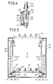
- the intervening space between the two inclined faces 34a is narrowed upward as shown in Fig. 5.
- a driving shaft 35 is rotatably supported on the bottom plate 7 over the distance between the side plates 33 along the running direction of the bobbin changing apparatus AD.
- Driving sprockets 36 are secured to the both end portions of the driving shaft 35 between the full bobbin guide bars 25 and the side plates 33 in both sides, and a sprocket 37 is secured to one end of the driving shaft 35 which projects toward the running wheel beyond the side plate 33 as shown in Fig. 2B.
- a chain 40 is mounted between this sprocket 37 and a sprocket 39 of the rotation shaft of a driving motor 38.
- Driven sprockets 41 are rotatably supported on a respective bracket attached to the top plate 24 vertically above the corresponding driving sprockets 36, and lifting chains 42 are mounted between left and right corresponding driving and driven sprockets 36 and 41, respectively (Fig. 1).
- a cam lever 46 having a cam follower 45 is connected by a key to one end of a shaft 47 rotatably mounted on the lift block 44 on the side of the corresponding side plate 33 and is swung in the front-rear direction (left-right direction in Fig. 6), and a fan-shaped sector gear 48 is connected by a key to the other end of the shaft 47.
- This sector gear 48 is engaged with a gear 51 of a swinging arm 50 supported by a supporting shaft 49 and swingably movable in the vertical direction.
- the shaft 49 is secured to each lift block 44.
- Each swinging arm 50 clips a stationary shaft 52 with the top end thereof and a pair of timing belt pulleys 53 integrally secured to both the left and right sides of the empty bobbin peg bar 19 are rotatably fitted to the corresponding swinging arm 50.
- a timing pulley 54 is connected by a key to the top end of each supporting shaft 49 so that the pulley 54 does not turn relative to the corresponding lift block 44.
- Timing belts 56 is mounted between the above-mentioned each pair of timing pulleys 54 and 53 through a respective tension pulley 55, so that even if the swinging arms 50 swing, the empty bobbin peg bar 19 is always kept at the horizontal posture.
- Driving sprockets 57 secured to a driving shaft 58 are rotatably supported at the bottom plate 7 of the machine body 6 of the bobbin changing apparatus in the rear of the empty bobbin guide bars 43, and a driven sprocket 59 is secured to one end of the driving shaft 58 and a driving chain 62 is mounted between this sprocket 59 and a sprocket 61 of a driving motor 60 (see Figs. 1 and 3).
- Driven sprockets 63 corresponding to the driving sprockets 57 are pivoted in the vicinity of the top plate 24 vertically above the driving sprockets 57.
- a pair of lift chains 64 are mounted between each pair of these driving and driven sprockets 57 and 63, and an intermediate part of each chain 64 is connected to the rear face of the corresponding lift block 44 (see Fig. 6).
- Grooved cam plates 64 having a cam groove 65a, in which the cam followers 45 are fitted and guided, are secured to the inner sides of the left and right side plates 33.
- Each cam groove 65a is formed to have a cam groove shape such that with the vertical movement of each lift blocks 44, the empty bobbin peg bar 19 can be displaced along a locus T shown in Fig.
- each peg 20 is located in the rear of the empty bobbin guide bar 43 so that the pegs 20 do not interfere with the vertical movement of the full bobbin peg bar 19 carrying full bobbins FB thereon.
- the upper receiving position S8 of the empty bobbin peg bar 19 and the common upper transfer position S6 and completion position (fall end) S5 of the common lower transfer position of the empty bobbin peg bar 19 are in agreement with the respective positions S4, S2, and S1 of the full bobbin peg bar 19.
- the lift device for the empty bobbin peg bar 19 is thus constructed with a mechanism for forward-backward movement.
- brackets 67 are arranged on the left and right sides at positions equidistant with respect to the bobbin changing center CL.
- Horizontal guide bars 68 are laterally arranged between the brackets 67 and rear plates 66.
- a supporting block 69c is secured on the axial line of the bobbin changing center CL and a feed bar 69a parallel to the horizontal bars 68 is rotatably supported between the supporting block 69c and the rear plate 66.
- a sprocket 69b is secured to the end of the feed bar 69a on the side of the rear plate 66, and a chain 71 b is mounted between this sprocket 69b and a sprocket 85 of a motor 70.
- a feed screw 72 is formed on the feed bar 69a substantially along the entire length thereof.
- Legs of a gate-like slide base 73 are fitted in the horizontal guide bars 68 movably in the front-rear direction, and a plate 74 is secured to the lower faces of the legs.
- a feed bracket 75 having a female screw engaged with the feed screw 72 of the feed bar 69 is secured to this plate 74.
- Lift bars 77 arranged vertically on the left and right lower parts of a bobbin changing bar 76 are vertically movably fitted on the upper portions of the legs of the slide base 73 respectively.
- a lift screw lever 78 is vertically mounted at an intermediate part between the lift bars 77 of the bobbin changing bar 76, and a female screw 80 of a driving sprocket 79 rotatably supported on the slide base 73 is screwed to the screw lever 78.
- a chain 83 is mounted between the driving sprocket 79 and a sprocket 82 of a driving motor 81 secured to the slide base 73.
- the bobbin changing bar 76 can make a forward-backward movement on the front side of the roving frame and a vertical movement.
- the upper face of the bobbin changing bar 76 is opened to form sliding faces 84, and sliders 85 and 86 for the front and rear rows, which have bobbin changing arms (bobbin changing arms for the front and rear rows) described below, are alternately arranged on the sliding faces 84 in the order of the slider for the front row and the slider for the rear row from the left side, when seen from the back face of the machine body 6 of the bobbin changing apparatus AD, as shown in Fig. 9.
- the sliders 85 and 86 are movable only in the left-right direction (Fig.
- a groove cam 93 having cylindrical cam grooves 93A and 93B formed on both sides with a distance corresponding to the distance between the sliders 85 and 86 for the front and rear rows, is slidably spline-fitted to the spline shaft 89.
- Cam followers 95 are arranged on the lower faces of the sliders 85 and 86 for the respective front and rear rows at positions corresponding to the cam grooves 93A and 93B. These cam followers 95 are engaged with the corresponding cam grooves.
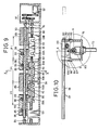
- the sliders 85 and 86 for the respective front and rear rows slide in two adjacent groove cams, except those located on both the ends, and when these groove cams 93A and 93B are turned by a predetermined angle e (between points A and B shown in Fig. 10), the slider pitch is changed from P1 to P (or vice versa) (Fig.
- Each slider 85 for the front row has, integrated therewith, each bobbin changing arm 96 for the front row, which can confront the row of bobbin wheels 5a of the roving frame 1, and the bifurcate top end of the slider 85 supports a flange B1 of the upper portion of the bobbin from below.
- Each one of sliders 86 for two bobbins of the rear row is provided with a bobbin changing arm 97 for the corresponding one of two bobbins of rear row, which can confront the row of bobbin wheels 5b, and each bobbin changing arm 97 for the bobbins of rear row has bifrucated fork portion connecting the tip ends of left and right guide levers 98.
- the guide levers 98 are inserted in slide apertures 99 of the respective sliders 86 for the two bobbins of the rear row so that the bobbin changing arms 97 for the two bobbins of the rear row can slide in the front-rear direction.
- Racks 100 are formed on the lower sides of each guide lever 98.
- a pinion 101 rotatably supported on each slider 86 for the rear row is engaged with the rack 100.
- the pinion 101 is spline-fitted to the spline shaft 90 and each slider 85 for the bobbin of front row is freely fitted to the corresponding spline shaft 90.
- the device for changing the front-rear distance between the bobbin changing arms 96 and 96 for the respective front and rear rows is thus constructed.
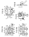
- the tooth numbers of respective gears of the gear row 91 are set so that when the spline shaft 89 is turned by e, each bobbin changing arm 97 for the rear row is displaced by L, and the operation of changing the zigzag arrangement of bobbins of one staff in the roving frame 1 to the arrangement in agreement with the bobbin arrangement of the spinning creel (or reverse change), as shown in Fig. 11, can be synchronously performed by one driving motor 92.
- proximity switches SW1 through SW8 are arranged at predetermined positions in the vertical direction.
- the proximity switches SW1 through SW4 are for detecting approach members 102 (Fig. 2) mounted on the slide blocks 26 of the full bobbin peg bar 18, and these proximity switches SW1 through SW4 confirm, in the order form below, the preparation position (lower end) S1 of the position for lower transfer operation of the full bobbin peg bar 18, the slightly elevated receiving position S2 of the above-mentioned position for the lower transfer operation, and the intermediate stop position S3 and the position for upper transfer operation S4, respectively, to stop the driving motor 38 (Fig. 3) and stop the full bobbin peg bar 18 at the respective positions.
- the proximity switches SW5 through SW8 are for detecting approach members 103 (Fig. 3) projected from the rear faces of the slide blocks 44 of the empty bobbin peg bar 19, and these proximity switches SW5 through SW8 confirm, in the order from below, the completion position (lower end) S5 of the position for lower transfer operation of the empty bobbin peg bar 19, the slightly elevated receiving position S6 of the position for the lower transfer operation, the stand-by position S7 shown in Fig. 8, and the position for upper transfer operation S8, respectively, to stop the driving motor 60 (Fig. 3) and stop the empty bobbin peg bar 19 at the respective positions.
- Limit switches LS1 through LS3 are for confirming the retreat end of the slide base 73, the transfer position (the position where the forks of the bobbin changing arms 96 and 97 for the bobbins of front and rear rows are arranged in one line vertically above the line of the pegs of the full bobbin peg bar 18), and the front ends of the forks of zigzag bobbin changing arms for the respective bobbins of front and rear rows on zigzag bobbin wheels, and the limit switches LS1 through LS3 are energized by a dog 104 attached to the leg of the slide base 73 to stop the slide base 73 at the respective positions. Furthermore, as shown in Fig.
- a dog 105 is attached to one slide bar 77 on the lower face of the slide base 77 and upper and lower limit switches LS4 and LS5 are arranged on the slide based through brackets to confirm the rise end and drop end of the bobbin changing bar 76 and stop the bobbin changing bar 76 at the respective positions.
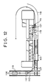
- a roving bobbin transporting unit CR used in combination with the bobbin changing apparatus AD of the present invention will now be described with reference to Fig. 2 and Figs. 12 through 17.
- a main transporting rail connecting the roving frame 1 to the creel of the spinning frame (not shown) is laid out above the end side of the machine frame.
- a branched transporting rail 111 on the side of the roving frame is connected to the main transporting rail 110 through a changeover switch device 112.
- the branched transporting rail 111 is disposed vertically above the full bobbin peg bar 18 of the bobbin changing apparatus AD at the time of bobbin changing along the bobbin wheels 5a and 5b of the roving frame 1 and is laid out at the rear of the machine frame while bypassing the outer end side of the machine frame.
- Each of the transporting rails 110 and 111 has a rectangular cross-section having the lower side opened, and wheels 113 roll within the transporting rails 110 and 111 to displace bobbin transporting members 114 for the transportation of roving bobbins along the transporting rails 110 and 111.
- a plurality (6 in the present embodiment) of bobbin supporting members 116 are suspended from the lower side of a base plate 116 of the bobbin transporting member 114 while keeping the bobbin pitch P of the spinning creel in the longitudinal direction between two adjacent bobbin supporting members 116.
- the bobbin transporting members 114 are connected to each other through a connecting lever 117, These bobbin transporting member 114 are connected so that roving bobbins of one roving frame can be held, whereby a large bobbin transporting unit 118 is constructed.
- the bobbin changing centers are set at points L1, L2, Vietnamese, that is, these centers are set at the center between the second and third bobbin supporting member 116 members counted from the bobbin supporting member 116 located on the right end in Fig. 2A and the positions apart from this center by 4.P and multiples thereof.
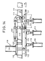
- a driving device 119 which is provided with a mechanism for displacing the transporting unit 118, is mounted on the transporting rail 110 in a condition wherein it is capable of running on the branched transporting rail.
- a plurality of driving devices 119 are arranged at intervals shorter than the entire length of the transporting unit 118. In this driving device 119 (Figs.
- swinging arms 122 are supported swingably in the horizontal direction with a vertical shaft 121 on both sides of a base 120 secured across the transporting rails 110 and 111, a rotary disk 123 is rotatably supported on one swinging arm 122, and a rotary disk 125 attached to a driving motor 124 is rotatably supported on the other swinging arm 122, so that the rotary disk 125 confronts the rotary disk 123.
- the base plate 115 of the bobbin transporting member 114 is clipped from both sides by the force of a spring 126 and the rotary disk 125 is positively driven to move the bobbin transporting unit 118.
- a proximity switch PX for detecting the positioning split cotter pin 127 is attached to the transporting rail 111 through a bracket 128 (see Fig. 15). On the side opposite to the proximity switch PX, a catcher 129 is swung by the operation of a cylinder 130 mounted on the rail 111. (see Fig. 14).
- the transporting unit 118 is at the first bobbin changing position L1
- the first positioning split cotter pin 127 confronts the proximity switch PX and the catcher 129 is capable of engaging to the split cotter pin 127, and after the completion of the bobbin change operation for the first bobbin transporting member 114, the catcher 129 is capable of disengaging from this positioning split cotter pin 127.
- the driving motor 124 and cylinder 130 make a one-pitch (P4) feeding of the bobbin transporting unit 118, and after completion of the bobbin changing operation, displace the bobbin transporting unit 118 to the spinning process to feed full roving bobbins to the spinning frames, and displace the bobbin transporting unit having empty bobbins EB to the roving frames which must carry out the bobbin changing operation by a control circuit 210 shown in Fig. 17.
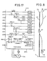
- a controller SPC is disposed to control the driving motor 124, and turning-ON and turning-OFF of the motor and changing of the rotation speed or rotation direction are controlled by opening and closing contacts RMH-1 and the like.
- the changeover switch device 112 (see Fig. 16) comprises a supporting bracket 131 secured to the transporting rail 110 and a solenoid 133 turnably mounted to the bracket 131, a swing arm 134 turnably pivoted on a free end portion of a piston of the solenoid 133, a delivery course changeover plate 32, one end portion of which is connected by a pin to the other end of the swing arm 134 in a condition such that the plate 132 is capable of taking two guide positions for guiding the transporting unit 118 along the transporting rail 110 or to the branched transporting rail 111.
- the bobbin changing operation by the above-mentioned preferable embodiment will be hereinafter described in detail.
- the transporting unit 118 having empty bobbins EB is displaced to the branched transporting rail 111 along the front face of the roving frame 1 from the main transporting rail 110.
- the driving device 119 closes a contact Hi of a high speed switch of the circuit 205 shown in Fig.
- a contact RTHR-1 connected to the controller SPC of the circuit 209 is closed and the forward end of the cylinder 130 turns ON the forward end limit switch LSA (circuit 200) to turn ON a relay RLSA, whereby a contact RLSA-2 of the contact 206 is closed to turn ON a relay RMH and close contacts RMH-1 and RMH-2 of the circuit 209, and the driving motor 124 (Fig. 14) of the driving device 119 is reversed at a high speed to displace the transporting unit 118 at a high speed by the rotary disk 125.
- the proximity switch 135 As shown in Fig.
- the contact Hi of the circuit 205 is opened and the solenoid SOL is changed over to retreat the cylinder 130 and engage the catcher 129 with the first positioning split cotter pin 127, whereby the bobbin changing center L1 of the transporting unit 118 is made to correspond with the bobbin changing center CL1 of the roving frame 1 and the transporting unit 118 is stopped at the bobbin changing position.
- the bobbin changing bar 76 is located at the position of the lower end or retreat end (stand-by position), the full bobbin peg bar 18 is located at the preparation position (lower end position) S1 of the common lower transfer position and the empty bobbin peg bar 19 is located at the stand-by position S7 (Fig. 18A).
- the one-line arrangement of the bobbin changing arms 96 and 97 for the respective front and rear rows of the bobbin wheels (hereinafter refers only to the respective front and rear rows) is changed to the zigzag arrangement, and simultaneously, by rotating the feed bar 69a, bobbin changing bar 76 is advanced toward the full bobbins FB on the respective bobbin wheels 5a, 5b and is stopped at the forward end.
- the forks of the bobbin changing arms 96 and 97 for the respective front and rear rows are inserted below the upper flanges BT of the corresponding full bobbins FB and the lift screw lever 78 is turned to raise the bobbin changing bar 76 to the rise end and suspend the full bobbins FB on the respective bobbin changing arms 96 and 7 for the respective front and rear rows.
- the empty bobbin peg bar 9 is moved forward from the standby position S7 by driving the lift chains 64, and raised to the upper transfer position S8, and four empty bobbins EB of the transporting unit 118 at the bobbin changing position are loaded on the pegs 20 of the empty bobbin peg bar 9 (Fig. 18B).
- the empty bobbin peg bar 19 having the empty bobbins EB loaded thereon is displaced downward, and retreated and stopped at the stand-by position S7.
- the bobbin changing bar 76 is being retreated, the bobbin changing arms 96 and 97 for the respective front and rear rows, which have the full bobbins FB suspended therefrom, are re-arranged from the zigzag arrangement into a one-line arrangement, and the bobbin changing arms 96 and 97 for the respective front and rear rows are stopped at the transfer position where the respective full bobbins FB taken out are located vertically above the respective pegs 20 of the full bobbin peg bar 18.
- the full bobbin peg bar 18 is slightly elevated, and the full bobbins FB are placed on the respective pegs 20 at the receiving position S2 (see Fig. 18C). Then, the bobbin changing bar 76 is retreated to the retreat end and the lift chain 42 are driven to elevate the full bobbin peg bar 18 upward in the vertical direction and attach the full bobbins FB to the bobbin supporting member 116.
- the empty bobbin peg bar 19 located at the stand-by position S7 is displaced downward to the lower transfering position S6 where the bobbin changing arms 96 and 97 of the bobbin changing bar 76 for the respective front and rear rows, located at the elevated end and retreat end in the one-line arrangement, are at a height allowing insertion of their furcate free end portions into the upper flanges BT of the corresponding empty bobbins EB (Fig. 18D).
- the full bobbin peg bar 18 is displaced downward and stopped at the intermediate stop position S3, and the bobbin changing arms 96 and 97 for the respective front and rear rows, which are located at the rise end and retreat end in the one-line arrangement, are advanced and stopped at the above-mentioned transfer position and the furcate free end portions of the bobbin changing arms 96 and 97 are inserted below the respective upper flanges BT of the corresponding empty bobbins EB.
- the empty bobbin peg bar 19 is then slightly displaced downward and located at the completion position (lower end position) S5 of the common lower transfer position which coincides with the above mentioned position S6, and the empty bobbins EB are suspended in a one-line arrangement of the bobbin changing arms 96 and 97 for the respective front and rear rows (Fig. 18E). Then, while the one-line arrangement of the bobbin changing arms 96 and 97 for the respective front and rear rows is changed to the zigzag arrangement, the bobbin changing bar 76 is located on the advance end and the bobbin changing bar 76 is displaced downward, and the empty bobbins EB are attached to the corresponding empty bobbin wheels 5a and 5b of the roving frame 1 (Fig. 18F).
- the bobbin changing bar 76 is retreated to the retreat end, and the zigzag arrangement of the bobbin changing arms 96 and 97 for the front and rear rows is changed to the one-line arrangement (Fig. 18G). Then, the empty bobbin peg bar 19 located at the completion position S5 of the common lower transfer position is displaced upward to the stand- by position S7 and the full bobbin peg bar 8 located at the intermediate stop position S3 is displaced downward to the preparation position S1 of the common lower tranfer position, see Fig. 18.H.
- the bobbin changing apparatus AD When one cycle of the bobbin changing operation is thus completed, the bobbin changing apparatus AD is displaced to the position for the next bobbin changing operation. At this point, a contact Pi (for issuing a one-pitch feed signal) of the circuit 201 shown in Fig. 17 is closed to turn ON a relay RTP. Thereupon, a contact TRP-1 of the circuit 208 is turned OFF to effect changeover of the solenoid SOL of the solenoid valve of the cylinder 130, and the cylinder 130 is advanced to swing the catcher 129 upward and release the engagement with the first positioning split cotter pin 127.
- a contact Pi for issuing a one-pitch feed signal
- a contact TRP-1 of the circuit 208 is turned OFF to effect changeover of the solenoid SOL of the solenoid valve of the cylinder 130, and the cylinder 130 is advanced to swing the catcher 129 upward and release the engagement with the first positioning split cotter pin 127.
- the cylinder 130 turns ON the limit switch LSA to turn ON a relay RLSA, and a contact RLSA-1 of the circuit 202 is turned ON and a relay RMP is turned ON. Accordingly, contacts RMP-1 and RMP-2 of the controller SPC of the circuit 209 are turned ON to rotate the driving motor 124 at a low speed in the normal direction and move the transportation unit 118 in the direction of arrow B in Fig. 19.
- the proximity switch contact PX of the circuit 203 and relay RPX are turned ON (at this point, the contact PI is turned OFF), and the contact RPX-1 of the circuit 201 is turned OFF, the relay RTP is turned OFF, RPX-2 of the circuit 204 is turned ON and a timer TR is turned ON.
- the contact TRP-1 of the circuit 208 is turned ON to effect changeover of the solenoid SOL, and the timer TR turns the driving motor 124 in the normal direction excessively for a predetermined time so that the cylinder 130 is retreated, the catcher 129 is brought down, the transportation unit 118 is displaced at a low speed, the second positioning split cotter pin 127 which has been moved is caught by the catcher 129, and the second positioning split cotter pin 127 is firmly pressed to the front end portion of the catcher 129.
- the timer TR runs out, the timer contacts TR-1 and TR-2 are turned OFF, the relays RMP and RPX are turned OFF, the timer TR is reset, and the driving motor 124 is stopped.
- the transporting unit 18 is displaced by one pitch P4, and as shown in Fig. 19B, the bobbin changing center C1 of the bobbin changing apparatus AD is made to correspond with the second bobbin changing centers CL1 and L2 of the roving frame 1 and the transporting unit 118, and the second bobbin changing operation is started.
- the contact Hi is closed at the circuit 205 to turn ON the relay RTH and turn OFF the contact RTH-1 and to effect changeover of the solenoid SOL, whereby the cylinder 130 for the catcher 129 is advanced to elevate the catcher 129 and the limit switch LSH at the advance end is turned ON to turn ON the relay RLSA and turn ON the relay RMH.
- the contacts RMH-1 and RMH-2 connected to the controller of the circuit 209 are closed, and at this point, since the contact RTHR-2 is closed, the driving motor 124 is rotated at a high speed in the normal direction and the transporting unit 118 suspending full bobbins for one spinning frame is transported to the position adjacent to the creel of the spinning frame.
- a sufficient vertical space is formed between the lower ends of the bobbins suspended from the transporting unit 118 and the top end of the bobbin changing apparatus AD. Accordingly, as shown in Fig. 12, in the portion CP where the transporting rails 110 and 111 cross the running rail of the bobbin changing apparatus AD in one plane, even if the transporting unit 118 having bobbins suspended therefrom is superposed on the bobbin changing apparatus AD in a plane, since the transporting unit 118 is not superposed on the bobbin changing apparatus AD in the vertical direction, layout of the transporting rail and the running rail of the bobbin changing apparatus AD or a running rail 136 (Fig. 12) for a truck for loading and moving the bobbin changing apparatus along the side face of the roving frame can be facilitated.
- the post treatment at the time of transporting doffed full bobbins to the spinning frame can be simplified.
- the rising slide block or lift block is further moved upward by utilizing this movement of raising the peg bars, and therefore, the actual rise end of the slide block or lift block is at a position lower than the upper transfer position of each peg bar and the height of the machine body of the bobbin changing apparatus can be effectively reduced.
- the position for controlling the bobbin changing bar can be set at three points (front end, rear end, and intermediate position), and the control of the bobbin changing bar is facilitated and the space necessary for the movement of the bobbin changing bar in the forward-backward direction is reduced.
- the full bobbin peg bar is raised to the receiving position from the preparation position and full bobbins are loaded on the full bobbin peg bar, but there may be adopted a modification in which the full bobbin peg bar is stopped at the receiving positon of the common lower transfer position and the bobbin changing bar is vertically moved to transfer full bobbins onto the full bobbin peg bar.
- a known battery car or the like may be used as the driving device of the transporting unit.
- bobbin changing bars for the respective front and rear rows of the bobbin wheels of a roving frame are not limited to those used in the present embodiment, but means using a screw feed mechanism or a cylinder, as disclosed in EP-A 0 148 129, may be used.
- the lift devices for full and empty bobbins utilize chains and chain sprockets, but lift devices utilizing a belt driving mechanism or other type of known lifting devices may be used.
- four bobbins are subjected to the bobbin changing operation at a time, but an appropriate number of bobbins may be treated at a time according to the arrangement of bobbin wheels in the roving frame.
- the same upper transfer position is used for the full bobbin peg bar and empty bobbin peg bar in the above-mentioned embodiment as the common upper transfer position, but there may be adopted a modification in which the forward-backward movement mechanism of the lift device for the empty bobbin peg bar is omitted, a vertical lift device similar to that for the full bobbin peg bar is used, and two rails for the full bobbin peg bar and the empty bobbin peg bar are arranged above the full bobbin peg bar and the empty bobbin peg bar, respectively.
- full bobbins are taken out on the full bobbin peg bar and attached to the bobbin supporting members of the full bobbin transporting rail located vertically above, and then the empty bobbin peg bar is raised to receive empty bobbins from the empty bobbin transporting rail, and after the empty bobbin peg bar is brought down, the bobbin changing arm is advanced and empty bobbins are fed to the roving frame.
Landscapes
- Engineering & Computer Science (AREA)
- Mechanical Engineering (AREA)
- Textile Engineering (AREA)
- Spinning Or Twisting Of Yarns (AREA)
Description
- The present invention relates to a bobbin changing method in a roving frame and an apparatus for carrying out this bobbin changing method. More particularly, the present invention relates to a bobbin changing method in a roving frame in which full bobbins held on a bobbin wheel of a roving frame, having a top-support-type flyer, are exchanged with empty bobbins suspended by the respective bobbin supporting members which are arranged in advance in upper corresponding positions above the roving frame, and an apparatus for carrying out this bobbin changing method.
- A bobbin changing apparatus, in which an operation of exchanging bobbins is carried out by a bobbin changer capable of running along a machine frame of a roving frame, is disclosed in Japanese Unexamined Patent Publication No. 50-89642. In this apparatus, the exchange of bobbins is carried out for each bobbin held by the respective bobbin wheels of the roving frame by one bobbin changing arm moving forward and backward and in the vertical direction. More specifically, the top portion of each of two empty bobbins suspended by the respective bobbin supporting members of a transporting apparatus is held and taken out by the bobbin changing arm and placed on the corresponding peg of a bobbin reserving mechanism, and the bobbin reserving mechanism is swung to retreat the empty bobbins to the position where the taking-out of each full bobbins is not disturbed. The full bobbins are then taken out from bobbin wheels by the bobbin changing arm and mounted on the corresponding bobbin supporting members supported by the transporting apparatus, and the bobbin reserving mechanism is returned to the original position and the full bobbins are held by the corresponding bobbin changing arms and fed onto the corresponding bobbin wheels of the roving frame.
- According to this conventional technique, since empty bobbins suspended by the bobbin supporting members are once taken out and placed on the corresponding pegs of the bobbin reserving mechanism, and the bobbin changing arms must travel two times between the respective bobbin wheels and the corresponding bobbin supporting members, and since only two empty bobbins can be simultaneously exchanged with full bobbins, the time required for the bobbin changing operation becomes long. Furthermore, since full and empty bobbins are moved forward and backward and in the vertical direction between the respective bobbin wheels and the corresponding bobbin supporting members in the state where the top portions of the bobbins are suspended by the respective bobbin changing arms, the overhang quantity of the bobbin changing arm holding heavy full bobbins becomes large and the height of the rising end of the bobbin changing arm also becomes large, and therefore, the bobbin changer becomes tall and unstable. Further, it is impossible to move the bobbin changing arm forward and backward and in the vertical direction at a high speed. Moreover, since the bobbin changing arm transfers full bobbins on the respective bobbin wheels of front and rear rows to the bobbin supporting members while maintaining the distance between the front and rear full bobbins as it is, the same distance as that between the full bobbins on the respective bobbin wheels of front and rear rows must be maintained between the bobbin supporting members of the transporting apparatus. If full bobbins suspended by the bobbin supporting members of the transporting apparatus are arranged in a zigzag manner, the automation of a roving bobbin exchange in a spinning frame becomes very difficult.
- To solve the above-mentioned problems, we developed a bobbin changing method and apparatus in which the bobbin reserving mechanism in the above-mentioned bobbin changing apparatus is omitted and each of the respective bobbin changing arms per se is moved along a course formed between the respective bobbin exchange positions of bobbin wheels of the roving frame and bobbin supporting members located above the roving frame (EP-A 0 148 129). According to this system, to exchange bobbins held on front and rear rows of bobbin wheels of the roving frame with bobbins on bobbin supporting members located above the roving frame, two bobbin changing arms, working separately for the front and rear rows of bobbin wheels, are used for full bobbins and empty bobbins, respectively, and independent moving mechanisms are used to cause the respective bobbin changing arms to make forward-backward movements and vertical movements between the respective bobbin wheels of the roving frame and the corresponding bobbin supporting members of a bobbin delivery means. Accordingly, the construction becomes complicated and it is impossible to design the bobbin changing apparatus in a compact form. Furthermore, accordig to this system, since bobbins are held by suspending upper flange portions of the bobbins with the bobbin changing arm, it is necessary to elevate the bobbin changing arm to such a position level at which it is adjacent to the bobbin supporting members of the bobbin transporting apparatus, and the height of the bobbin changing apparatus per se becomes large. Accordingly, the bobbin changing apparatus becomes unstable, and the bobbins suspended by the bobbin supporting members interfere with the bobbin changing apparatus, and the bobbin changing apparatus cannot pass below the bobbins. Therefore, it is impossible to adopt a layout in which the transporting rails for the transporting apparatus and the guide rail of the bobbin changing apparatus sterically cross each other, and it is difficult to automatically control the bobbin changing apparatus as a machine for carrying out the bobbin exchange operation for a group of many roving frames.
- It is a primary object of the present invention to provide a practical bobbin changing method applied for the roving process, by which the above-mentioned problems are solved, and an apparatus for use in carrying out this bobbin changing method.
- The basic technical idea for attaining this object is that the unitary cycle of bobbin changing work, consisting of the bobbin changing operation of displacing and exchanging full bobbins and empty bobbins between the respective bobbin wheels of a roving frame and the corresponding bobbin supporting members which are arranged in advance in upper corresponding positions above the roving frame concerned is divided into the step of vertically moving each one of the full bobbins and the corresponding one of the empty bobbins between a bobbin transfer position, which is common for each one of the full bobbins and the corresponding one of the empty bobbins, at the level of the bobbin wheels of the roving frame and a bobbin holding and releasing position of the bobbin supporting member, which is common for the each one of the full bobbins and the respective one of the corresponding empty bobbins, along the same course, except for a part thereof, and the step of transferring the bobbins between the respective bobbin wheels of the roving frame and the above-mentioned corresponding common bobbin transfer positions, whereby it is made possible to simultaneously perform the operation of receiving full bobbins from the bobbin wheels of the flyer frame and the operation of receiving empty bobbins from the bobbin supporting members, and it is also made possible to simultaneously perform at least parts of the operation of displacing the full bobbins received from the roving frame toward the respective bobbin supporting members, from which the empty bobbins have been taken out, and suspending the full bobbins on the corresponding bobbin supporting members, and the operation of displacing the empty bobbins taken out from the bobbin supporting members to the above-mentioned corresponding common bobbin transfer positions. Accordingly, the construction of the bobbin changing apparatus for carrying out this bobbin changing method is greatly simplified and the apparatus can be made compact, and the bobbin changing operation can be performed assuredly and promptly. Furthermore, since in the displacing courses for full bobbins and empty bobbins, the bobbin transferring position and the bobbin holding releasing position of each one of the bobbin supporting members are common to the corresponding full bobbin and empty bobbin, in order to avoid interference in the vertical movements of the full bobbins and empty bobbins, a stand-by position for each empty bobbin is formed in the displacing course for each one of the empty bobbins at a position deviated from a linear course connecting the above-mentioned holding and releasing position and the bobbin transferring position.
- In view of the desired compactness of the bobbin changing apparatus, where full bobbins are taken out from the respective bobbin wheels of the roving frame and displaced to the above-mentioned respective corresponding common bobbin transfer positions, and where empty bobbins are placed on the respective corresponding bobbin wheels of the roving frame from the respective common transfer positions, the bobbins are moved in the state where the upper flange portion of each bobbin is suspended; and where the full bobbins are elevated from their transfer positions to the respective corresponding bobbin holding and releasing positions of the bobbin supporting members and are held by the respective corresponding bobbin supporting members, and where the empty bobbins are received from the bobbin supporting members and are brought down to the above-mentioned respective transfer positions, the bobbins are displaced in the state where each bobbin is held at the bottom thereof. If this method is adopted, the manner of holding bobbins to be displaced is changed at the above-mentioned respective common bobbin transfer position. Accordingly, in the bobbin changing apparatus of a roving frame according to the present invention, the apparatus height can be effectively reduced, and thus the method according to the present invention contributes greatly to the compactness of the bobbin changing apparatus.
- The bobbin changing method in a roving frame based on the above-mentioned basic technical concept, according to the present invention, is a bobbin changing method in which the bobbin changing operation of a group of bobbins is carried out by using a bobbin changing apparatus for empty bobbins prepared and arranged in advance at an upper position of the roving frame and full bobbins held on bobbin wheels of the flyer frame. After completion of the above-mentioned unit operation for a group of bobbins, the bobbin changing apparatus is displaced along bobbin rails and is located at a position corresponding to bobbin wheels for the subsequent unit operation, and this unit operation is repeated, until the above-mentioned bobbin changing operation is completed for all bobbin wheels of a roving frame. This method is characterized by the following constitutional elements of the invention, that is, the bobbin changing operation is carried out by displacing full bobbins and empty bobbins along the respective bobbin moving courses formed between the positions of bobbin wheels of the roving frame and the corresponding positions for holding bobbins by the respective bobbin supporting members and releasing these bobbins therefrom above the roving frame; a common lower bobbin transfer position is formed in each of the above-mentioned bobbin displacing courses, to which position a full bobbin taken out from a bobbin wheel of the roving frame is carried before this bobbin is displaced to the above-mentioned position for holding by the corresponding bobbin supporting member and empty bobbin previously received from the corresponding supporting member is displaced before this empty bobbin is carried to a such position for mounting the corresponding bobbin wheel of the roving frame, at substantially the same height level as the height of the bobbin wheels within the bobbin changing apparatus; the bobbins are displaced along the respective displacing courses between the above-mentioned respective common lower transfer positions and the positions of the respective corresponding bobbin wheels, while holding the upper position of each bobbin, and the bobbins are displaced along the respective displacing courses between the respective common lower transfer positions and the holding and releasing positions of the respective corresponding bobbin supporting members while holding the lower portion of each bobbin; the state of holding each bobbin is changed to the other bobbin holding state at each common lower transfer position; and empty bobbins received from the respective bobbin supporting members are reserved for a while at a position deviated from the respective linear courses connecting the respective bobbin supporting members to the respective corresponding common lower transfer positions when the full bobbins are displaced to the corresponding bobbin supporting members from the above-mentioned respective common lower transfer positions during the unit operation of the bobbin changing operation. The above-mentioned position for holding a full bobbin by the corresponding bobbin supporting member and also for releasing an empty bobbin from this bobbin supporting member is hereinafter referred to as a common upper transfer position.
- As the method in which empty bobbins to be subjected to the bobbin changing operation are prepared and arranged in advance in the upper portion of the roving frame, there can be mentioned a method in which a bobbin transporting apparatus comprising a plurality of transporting members, each having a plurality of bobbin supporting members for suspending a bobbin is travelled along transporting rail means laid out in the longitudinal direction of the roving frame in the upper portion of the roving frame and is stopped at predetermined positions for carrying out the bobbin changing operation. Instead of this automatic method, there may be adopted a method in which a creel or creels for holding bobbin supporting members is arranged above the roving frame, empty bobbins are manually suspended by the bobbin supporting members in advance, these empty bobbins are exchanged with full bobbins by the bobbin changing operation of the present invention, and then are manually delivered out from the bobbin supporting members. Moreover, such a manual operation may be performed by a method similar to the known bobbin exchange method in a spinning frame, as disclosed in Japanese Unexamined Patent Publication No. 58-120826. In view of the above-mentioned, the bobbin changing method and apparatus of the present invention can be utilized in various modes according to actual conditions at the spinning mills.
- In the present invention, since application of an automatic system for supplying roving bobbins from the roving process to the spinning process is intended, the pitches of bobbin supporting members are made to correspond with the pitches of bobbin hangers of the creel of a spinning frame. Accordingly, when the operation is carried out in a roving frame in which front and rear rows (two rows) of bobbin wheels are arranged, this two-row arrangement is not in agreement with the one-row arrangement of the bobbin supporting members and the operation is disturbed by this disagreement. However, this problem can be practically solved by changing the pitches of bobbins held by the respective bobbin changing arms, and by changing the arrangement conditions between the zigzag arrangement and a linear arrangement, while the bobbins are displaced between the position of the bobbin wheels and the respective corresponding lower transfer positions.
- As is apparent from the above-mentioned description, in the apparatus for use in carrying out the bobbin changing method in a roving frame according to the present invention, a peg bar for full bobbins and a peg bar for empty bobbins, each having a plurality of bobbin holding pegs, are used for moving full bobbins and empty bobbins between the above-mentioned common lower transfer positions and the common upper transfer positions for the respective bobbin supporting members, these two peg bars are moved between the position coinciding to the common lower and upper bobbin transfer positions along the above-mentioned respective displacing courses except an intermediate stand-by position for each peg bar for empty bobbins, a carrying mechanism is used to carry full bobbins and empty bobbins between the respective bobbin wheels of the roving frame and the respective corresponding common lower bobbin transfer positions, the full bobbins received from the respective bobbin wheels of the roving frame are transferred to the respective corresponding peg bar for full bobbins at the respective corresponding common lower transfer positions, and the empty bobbins taken out from the respective bobbin supporting members to the peg bar for empty bobbins at the respective common upper transfer positions are displaced to the respective common lower transfer positions by displacing the peg bar for the empty bobbins downward, and these empty bobbins are transfered to the carrying mechanism from the peg bar for empty bobbin at the corresponding respective common lower transfer positions.
- Elements having different functions are combined in the above-mentioned manner to construct the apparatus of the present invention. Since these elements are arranged so that mutual interference is avoided among these elements, the apparatus is made compact by a combination of simple mechanisms, and therefore, the operation can be carried out in simple way and the operational steps can be promptly carried out. Accordingly, the practical value of the present invention is very high.
-
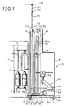
- Figure 1 is a side view of a bobbin changing apparatus for a roving frame, wherein a part of a bobbin transporting apparatus is shown;
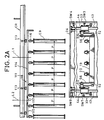
- Figure 2A is a front view of an upper portion of the bobbin changing apparatus, together with the part of the bobbin transporting apparatus shown in Fig. 1;
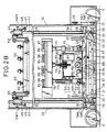
- Fig. 2B is a front view of the bobbin changing apparatus shown in Fig. 1 wherein the upper portion thereof is omitted;
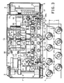
- Fig. 3 is a plan view of the bobbin changing apparatus shown in Fig. 1;
- Fig. 4 is a side view of a part of a lifting mechanism for a peg bar for full bobbins;
- Fig. 5 is a schematic front view of the bobbin changing apparatus, omitting machine elements except for the lifting mechanism for the peg bar for full bobbins, for illustrating the displacing operation of the peg bar for full bobbins;
- Fig. 6 is a side view of a main part of the lift mechanism for a peg bar for empty bobbins;
- Fig. 7 is a view taken along the line VII-VII in Fig. 6;
- Fig. 8 is a diagram illustrating the moving locus of the peg bar for empty bobbins;
- Fig. 9 is a sectional view of a bobbin changing bar of a bobbin carrying device mounted on the bobbin changing apparatus shown in Fig. 1;
- Fig. 10 is a view showing the section taken along the line X-X in Fig. 9;
- Fig. 11 A and Fig. 11B are diagrams illustrating the operation of a bobbin changing arms for front and rear rows which are mounted at the bobbin changing bar shown in Fig. 9;
- Fig. 12 is a plan view showing a bobbin transporting apparatus, a travelling rail and a roving frame, which are designed so that they are adapted to the bobbin changing apparatus in a roving frame according to the present invention;
- Fig. 13 is a plan view showing a connection unit of the bobbin transporting apparatus;
- Fig. 14 is a side view showing the unit transporting device and a positioning device thereof;
- Fig. 15 is a sectional view of a positioning device taken along the line XV-XV in Fig. 14.
- Fig. 16 is a plan view of a switching mechanism applied for the transporting apparatus shown in Fig. 12;
- Fig. 17 is an electric circuit diagram illustrating a control circuit for the transporting apparatus and positioning device;
- Figs. 18A, 18B, 18C, 18D, 18E, 18F, 18G, and 18H are drawings illustrating the operational steps of the bobbin changing process according to the present invention; and
- Figs. 19A and 19B are diagrams illustrating the positional relationship among the roving frame, the bobbin changing apparatus, and the transporting apparatus when the transporting apparatus shown in Fig. 12 is utilized.
- Some modifications may be made to the bobbin changing method in a roving frame according to the present invention when this method is practically carried out, but the above-mentioned basic technical idea should be always embodied. Accordingly, the bobbin changing apparatus in which this technical idea is embodied will now be described in detail with reference to a preferred embodiment illustrated in the accompanying drawings.
- Referring to Figs. 1 through 3, a bobbin changing machine AD is positioned at a predetermined position in front of a
roving frame 1. In thisroving frame 1, top support type front andrear flyers 3 are disposed in a zigzag manner on atop rail 2 of theroving frame 1 and one group of four topsupport type flyers 3 are arranged in one staff so that a pitch P1 (Fig. 3) is maintained betweenadjacent flyers 3 and a pitch P2 is maintained betweenadjacent flyers 3 of adjacent groups, in the longitudinal direction of thetop rail 2. Furthermore, a distance L is set between the front and rear rows of theflyers 3. Theflyers 3 are rotated at a high speed through driving shafts and gears (not shown) arranged within thetop rail 2. Below theflyers 3, abobbin rail 4 is vertically movably arranged, andbobbin wheels 5a and 5b concentric with theflyers 3 are arranged on thebobbin rail 4 and are rotated at a high speed through driving shafts and gears (not shown). - For a better understanding of the practical value of the bobbin changing method and apparatus of the present invention, an automatic bobbin changing system in which the above-mentioned bobbin transporting apparatus is used will now be described in detail. This automatic bobbin changing system comprises the bobbin changing apparatus AD of the present invention and a roving bobbin transporting apparatus CR located above a
roving frame 1. The bobbin changing apparatus AD is first described. - In the bobbin changing apparatus AD, running
wheels 9 secured towheel shafts 8 are rotatably supported on abottom plate 7 of abody 6 of the bobbin changing apparatus AD through a pair ofbearings 10 at front and rear parts thereof, in the running direction. A drivenpulley 11 is secured to one wheel 8 (the left wheel in Fig. 3) and atiming belt 14 is mounted between thispulley 11 and a drivingpulley 13 of a drivingmotor 12 located on thebottom plate 7. The runningwheels 9 are mounted on runningrails 15 laid out on the front floor surface of theroving frame 1 along the entire length of theroving frame 1, so as to be able to run in the longitudinal direction thereof.Approach members 16 are arranged at respective staff centers (bobbin changing centers CL1, CL2, ..., of the roving frame 1) betweenbobbin wheels 5a and 5b on the floor surface along the longitudinal direction of the machine frame. A proximity switch 17 capable of detecting theapproach member 16 is secured to thebottom plate 7 of themachine body 6 of the bobbin changing apparatus AD at a position conforming to the center of the pitch of bobbin changing arms for the respective second and third front and rear rows of a bobbin changing bar (described below as bobbin changing center CL of the bobbin changing apparatus AD). The construction of the bobbin changing bar and bobbin changing arms will be explained in detail later. When the drivingmotor 12 is driven, the bobbin changing apparatus AD is displaced on the running rails 15 along the front face of theroving frame 1, and when theapproach member 16 confronts the proximity switch 17, the bobbin changing apparatus AD is atopped at a predetermined bobbin changing position. - Full bobbin and empty bobbin peg bars 18 and 19 of the
machine body 6 and lifting mechanisms for these pegs will now be described in detail.Pegs 20 for one staff (four pegs) are arranged on the top face of the fullbobbin peg bar 18 so that the distance between twoadjacent pegs 20 is equal to the bobbin pitch P of a spinning creel. Eachpeg 20 is vertically slidable on the upper face of the fullbobbin peg bar 18 and is urged upward by a spring 21, and the top end of thepeg 20 is positioned by a fall- preventingscrew 22.Pegs 20 of the emptybobbin peg bar 19, described below, also have the same structure (see Fig. 6). Guide blocks 23 are secured to both the left and right ends of the fullbobbin peg bar 18, and these guide blocks 23 are slidably mounted on the corresponding respective guide bars 27 mounted perpendicularly to the corresponding respective slide blocks 26, which are slidably mounted on the corresponding respective guide bars 25 extended from the left and right end portions of thebottom plate 7 of themachine body 6 to thetop plate 24 thereof. One end of each of first andsecond links guide block 23 with the corresponding end of the fullbobbin peg bar 18, both ends of the fullbobbin peg bar 18 can be extended to create a pair of end portions having the same function as the above-mentionedguide block 23. Apin 31 on the side of eachslide block 26 is located vertically below apin 30 on the side of thecorresponding guide block 23. The other ends of the first andsecond links corresponding cam follower 32.Cam plates 34 confronting the correspondingcam followers 32 and having a inwardlyinclined face 34a are attached to left and rightouter side plates 33 of the full bobbin guide bars 25 of thebody 8, in the vertical direction of themachine body 6 substantially along the entire length thereof (thecam plates 34 are omitted in Figs. 1 and 2). The intervening space between the twoinclined faces 34a is narrowed upward as shown in Fig. 5. A drivingshaft 35 is rotatably supported on thebottom plate 7 over the distance between theside plates 33 along the running direction of the bobbin changing apparatus AD. Drivingsprockets 36 are secured to the both end portions of the drivingshaft 35 between the full bobbin guide bars 25 and theside plates 33 in both sides, and asprocket 37 is secured to one end of the drivingshaft 35 which projects toward the running wheel beyond theside plate 33 as shown in Fig. 2B. Achain 40 is mounted between thissprocket 37 and asprocket 39 of the rotation shaft of a drivingmotor 38. Driven sprockets 41 are rotatably supported on a respective bracket attached to thetop plate 24 vertically above the corresponding drivingsprockets 36, and liftingchains 42 are mounted between left and right corresponding driving and drivensprockets 36 and 41, respectively (Fig. 1). Intermediate parts of thelifting chains 42 are secured to the corresponding slide blocks 26 on the side faces in the direction of the running wheels. The lifting mechanism for the fullbobbin peg bar 18 is thus constructed, and as shown in Fig. 5, by the motion of thelifting chains 42, the slide blocks 26 are vertically displaced. When the slide blocks 26 move upward, the fullbobbin peg bar 18 is pushed up by the slide blocks 26 because the distance between the left andright cam followers 32 is contracted by engagement with the correspondingrespective cam plates 34, and the fullbobbin peg bar 18 is vertically moved among the common upper transfer position (rise end) S4 where full bobbins FB can be caught by the corresponding bobbin supporting members of abobbin transporting apparatus 114 described later, a receiving position S2 of the common lower transfer motion where full bobbins FB taken out from therespective bobbin wheels 5a and 5b by a bobbin changing bar described hereinafter and mounted on the corresponding pegs 20 on the fullbobbin peg bar 18, and led to a preparation position S1 (lowermost displaced position) of the common lower transfer motion below the receiving position S2. - As shown in Figs. 1 through 3 and 6 through 8, in the empty
bobbin peg bar 19, as in the above-mentioned fullbobbin peg bar 18, pegs 20 (four pegs) of one staff are arranged in a line, in a condition such that the distance between adjacent twopegs 20 is set at the pitch P in the spinning creel. The lifting mechanism for the emptybobbin peg bar 19 is now described. Empty bobbin guide bars 43 are arranged in parallel to the full bobbin guide bars 25 slightly obliquely behind the full bobbin guide bars 25, and alift block 44 is slidably fitted to each of the empty bobbin guide bars 43. In eachlift block 44, acam lever 46 having acam follower 45 is connected by a key to one end of ashaft 47 rotatably mounted on thelift block 44 on the side of thecorresponding side plate 33 and is swung in the front-rear direction (left-right direction in Fig. 6), and a fan-shapedsector gear 48 is connected by a key to the other end of theshaft 47. Thissector gear 48 is engaged with agear 51 of a swingingarm 50 supported by a supportingshaft 49 and swingably movable in the vertical direction. Theshaft 49 is secured to eachlift block 44. Each swingingarm 50 clips astationary shaft 52 with the top end thereof and a pair of timing belt pulleys 53 integrally secured to both the left and right sides of the emptybobbin peg bar 19 are rotatably fitted to the corresponding swingingarm 50. A timingpulley 54 is connected by a key to the top end of each supportingshaft 49 so that thepulley 54 does not turn relative to thecorresponding lift block 44. Timingbelts 56 is mounted between the above-mentioned each pair of timing pulleys 54 and 53 through arespective tension pulley 55, so that even if the swingingarms 50 swing, the emptybobbin peg bar 19 is always kept at the horizontal posture. Drivingsprockets 57 secured to a drivingshaft 58 are rotatably supported at thebottom plate 7 of themachine body 6 of the bobbin changing apparatus in the rear of the empty bobbin guide bars 43, and a drivensprocket 59 is secured to one end of the drivingshaft 58 and a drivingchain 62 is mounted between thissprocket 59 and asprocket 61 of a driving motor 60 (see Figs. 1 and 3). Driven sprockets 63 corresponding to the drivingsprockets 57 are pivoted in the vicinity of thetop plate 24 vertically above the drivingsprockets 57. A pair oflift chains 64 are mounted between each pair of these driving and drivensprockets 57 and 63, and an intermediate part of eachchain 64 is connected to the rear face of the corresponding lift block 44 (see Fig. 6).Grooved cam plates 64 having a cam groove 65a, in which thecam followers 45 are fitted and guided, are secured to the inner sides of the left andright side plates 33. Each cam groove 65a is formed to have a cam groove shape such that with the vertical movement of each lift blocks 44, the emptybobbin peg bar 19 can be displaced along a locus T shown in Fig. 8, and at the stand-by position S7 intermediate in the vertical direction, the axial center of each peg 20 is located in the rear of the emptybobbin guide bar 43 so that thepegs 20 do not interfere with the vertical movement of the fullbobbin peg bar 19 carrying full bobbins FB thereon. The upper receiving position S8 of the emptybobbin peg bar 19 and the common upper transfer position S6 and completion position (fall end) S5 of the common lower transfer position of the emptybobbin peg bar 19 are in agreement with the respective positions S4, S2, and S1 of the fullbobbin peg bar 19. The lift device for the emptybobbin peg bar 19 is thus constructed with a mechanism for forward-backward movement. - The full bobbin and empty bobbin carrying device will now be described with reference to Figs. 1 through 3 and 9 through 11. On the
bottom plate 7 of themachine body 6 of the bobbin changing apparatus AD,brackets 67 are arranged on the left and right sides at positions equidistant with respect to the bobbin changing center CL. Horizontal guide bars 68 are laterally arranged between thebrackets 67 andrear plates 66. A supportingblock 69c is secured on the axial line of the bobbin changing center CL and afeed bar 69a parallel to thehorizontal bars 68 is rotatably supported between the supportingblock 69c and therear plate 66. Asprocket 69b is secured to the end of thefeed bar 69a on the side of therear plate 66, and achain 71 b is mounted between thissprocket 69b and asprocket 85 of amotor 70. Afeed screw 72 is formed on thefeed bar 69a substantially along the entire length thereof. Legs of a gate-like slide base 73 are fitted in thehorizontal guide bars 68 movably in the front-rear direction, and aplate 74 is secured to the lower faces of the legs. Afeed bracket 75 having a female screw engaged with thefeed screw 72 of the feed bar 69 is secured to thisplate 74. Lift bars 77 arranged vertically on the left and right lower parts of abobbin changing bar 76 are vertically movably fitted on the upper portions of the legs of theslide base 73 respectively. A lift screw lever 78 is vertically mounted at an intermediate part between the lift bars 77 of thebobbin changing bar 76, and a female screw 80 of a drivingsprocket 79 rotatably supported on theslide base 73 is screwed to the screw lever 78. A chain 83 is mounted between the drivingsprocket 79 and a sprocket 82 of a drivingmotor 81 secured to theslide base 73. Accordingly, thebobbin changing bar 76 can make a forward-backward movement on the front side of the roving frame and a vertical movement. As shown in Fig. 10, the upper face of thebobbin changing bar 76 is opened to form sliding faces 84, andsliders machine body 6 of the bobbin changing apparatus AD, as shown in Fig. 9. Thesliders rear slider holders bobbin changing bar 76. Twospline shafts bobbin changing bar 76 rotatably along the longitudinal direction of the machine frame, and one end of each of the twospline shafts motor 92 through agear row 91. Agroove cam 93 havingcylindrical cam grooves sliders spline shaft 89. Amember 94 for regulating the left-right movement of thegroove cam 93, which is in sliding contact with both the left and right ends of thegroove cam 93, is secured to thebobbin changing bar 76.Cam followers 95 are arranged on the lower faces of thesliders cam grooves cam followers 95 are engaged with the corresponding cam grooves. Thesliders groove cams slider 85 for the front row has, integrated therewith, eachbobbin changing arm 96 for the front row, which can confront the row of bobbin wheels 5a of theroving frame 1, and the bifurcate top end of theslider 85 supports a flange B1 of the upper portion of the bobbin from below. Each one ofsliders 86 for two bobbins of the rear row is provided with abobbin changing arm 97 for the corresponding one of two bobbins of rear row, which can confront the row ofbobbin wheels 5b, and eachbobbin changing arm 97 for the bobbins of rear row has bifrucated fork portion connecting the tip ends of left and right guide levers 98. The guide levers 98 are inserted inslide apertures 99 of therespective sliders 86 for the two bobbins of the rear row so that thebobbin changing arms 97 for the two bobbins of the rear row can slide in the front-rear direction.Racks 100 are formed on the lower sides of eachguide lever 98. Apinion 101 rotatably supported on eachslider 86 for the rear row is engaged with therack 100. Thepinion 101 is spline-fitted to thespline shaft 90 and eachslider 85 for the bobbin of front row is freely fitted to thecorresponding spline shaft 90. The device for changing the front-rear distance between thebobbin changing arms gear row 91 are set so that when thespline shaft 89 is turned by e, eachbobbin changing arm 97 for the rear row is displaced by L, and the operation of changing the zigzag arrangement of bobbins of one staff in theroving frame 1 to the arrangement in agreement with the bobbin arrangement of the spinning creel (or reverse change), as shown in Fig. 11, can be synchronously performed by one drivingmotor 92. - On the inner sides of the left and
right side plates 33 of themachine body 6 of the bobbin changing apparatus, proximity switches SW1 through SW8 are arranged at predetermined positions in the vertical direction. The proximity switches SW1 through SW4 are for detecting approach members 102 (Fig. 2) mounted on the slide blocks 26 of the fullbobbin peg bar 18, and these proximity switches SW1 through SW4 confirm, in the order form below, the preparation position (lower end) S1 of the position for lower transfer operation of the fullbobbin peg bar 18, the slightly elevated receiving position S2 of the above-mentioned position for the lower transfer operation, and the intermediate stop position S3 and the position for upper transfer operation S4, respectively, to stop the driving motor 38 (Fig. 3) and stop the fullbobbin peg bar 18 at the respective positions. The proximity switches SW5 through SW8 are for detecting approach members 103 (Fig. 3) projected from the rear faces of the slide blocks 44 of the emptybobbin peg bar 19, and these proximity switches SW5 through SW8 confirm, in the order from below, the completion position (lower end) S5 of the position for lower transfer operation of the emptybobbin peg bar 19, the slightly elevated receiving position S6 of the position for the lower transfer operation, the stand-by position S7 shown in Fig. 8, and the position for upper transfer operation S8, respectively, to stop the driving motor 60 (Fig. 3) and stop the emptybobbin peg bar 19 at the respective positions. Limit switches LS1 through LS3 are for confirming the retreat end of theslide base 73, the transfer position (the position where the forks of thebobbin changing arms dog 104 attached to the leg of theslide base 73 to stop theslide base 73 at the respective positions. Furthermore, as shown in Fig. 2, adog 105 is attached to oneslide bar 77 on the lower face of theslide base 77 and upper and lower limit switches LS4 and LS5 are arranged on the slide based through brackets to confirm the rise end and drop end of thebobbin changing bar 76 and stop thebobbin changing bar 76 at the respective positions. - A roving bobbin transporting unit CR used in combination with the bobbin changing apparatus AD of the present invention will now be described with reference to Fig. 2 and Figs. 12 through 17.
- A main transporting rail connecting the
roving frame 1 to the creel of the spinning frame (not shown) is laid out above the end side of the machine frame. A branched transportingrail 111 on the side of the roving frame is connected to the main transportingrail 110 through achangeover switch device 112. The branched transportingrail 111 is disposed vertically above the fullbobbin peg bar 18 of the bobbin changing apparatus AD at the time of bobbin changing along thebobbin wheels 5a and 5b of theroving frame 1 and is laid out at the rear of the machine frame while bypassing the outer end side of the machine frame. Each of the transportingrails wheels 113 roll within the transportingrails bobbin transporting members 114 for the transportation of roving bobbins along the transportingrails bobbin supporting members 116 are suspended from the lower side of abase plate 116 of thebobbin transporting member 114 while keeping the bobbin pitch P of the spinning creel in the longitudinal direction between two adjacentbobbin supporting members 116. Thebobbin transporting members 114 are connected to each other through a connectinglever 117, Thesebobbin transporting member 114 are connected so that roving bobbins of one roving frame can be held, whereby a largebobbin transporting unit 118 is constructed. The bobbin changing centers are set at points L1, L2, ....., that is, these centers are set at the center between the second and thirdbobbin supporting member 116 members counted from thebobbin supporting member 116 located on the right end in Fig. 2A and the positions apart from this center by 4.P and multiples thereof. A drivingdevice 119, which is provided with a mechanism for displacing the transportingunit 118, is mounted on the transportingrail 110 in a condition wherein it is capable of running on the branched transporting rail. A plurality of drivingdevices 119 are arranged at intervals shorter than the entire length of the transportingunit 118. In this driving device 119 (Figs. 13 and 14), swingingarms 122 are supported swingably in the horizontal direction with avertical shaft 121 on both sides of a base 120 secured across the transportingrails rotary disk 123 is rotatably supported on one swingingarm 122, and arotary disk 125 attached to a drivingmotor 124 is rotatably supported on the other swingingarm 122, so that therotary disk 125 confronts therotary disk 123. - The
base plate 115 of thebobbin transporting member 114 is clipped from both sides by the force of aspring 126 and therotary disk 125 is positively driven to move thebobbin transporting unit 118. On thebase plates 115 of thesebobbin transporting members 114 located in the rear (the right side in Figs. 14, 19A, 19B) of thebobbin transporting unit 118, positioning splitcotter pins 127 in a number corresponding to the frequency of stoppage for bobbin changing in one roving frame are secured while maintaining the mutual pitch P4 which coincides with the difference between one movement pitch (3•P1 +P2) of the bobbin changing apparatus AD and the bobbin changing center pitch (4.P) of the bobbin transporting member 114 (see Fig. 3). A proximity switch PX for detecting the positioning splitcotter pin 127 is attached to the transportingrail 111 through a bracket 128 (see Fig. 15). On the side opposite to the proximity switch PX, acatcher 129 is swung by the operation of acylinder 130 mounted on therail 111. (see Fig. 14). When the transportingunit 118 is at the first bobbin changing position L1, the first positioning splitcotter pin 127 confronts the proximity switch PX and thecatcher 129 is capable of engaging to the splitcotter pin 127, and after the completion of the bobbin change operation for the firstbobbin transporting member 114, thecatcher 129 is capable of disengaging from this positioning splitcotter pin 127. At the time of carrying out the bobbin changing operation, the drivingmotor 124 andcylinder 130 make a one-pitch (P4) feeding of thebobbin transporting unit 118, and after completion of the bobbin changing operation, displace thebobbin transporting unit 118 to the spinning process to feed full roving bobbins to the spinning frames, and displace the bobbin transporting unit having empty bobbins EB to the roving frames which must carry out the bobbin changing operation by acontrol circuit 210 shown in Fig. 17. In this control circuit, a controller SPC is disposed to control the drivingmotor 124, and turning-ON and turning-OFF of the motor and changing of the rotation speed or rotation direction are controlled by opening and closing contacts RMH-1 and the like. The changeover switch device 112 (see Fig. 16) comprises a supportingbracket 131 secured to the transportingrail 110 and asolenoid 133 turnably mounted to thebracket 131, aswing arm 134 turnably pivoted on a free end portion of a piston of thesolenoid 133, a deliverycourse changeover plate 32, one end portion of which is connected by a pin to the other end of theswing arm 134 in a condition such that theplate 132 is capable of taking two guide positions for guiding the transportingunit 118 along the transportingrail 110 or to the branched transportingrail 111. - The bobbin changing operation by the above-mentioned preferable embodiment will be hereinafter described in detail. When an advance instruction to start the bobbin changing operation is electrically sent to a particular
roving frame 1, the transportingunit 118 having empty bobbins EB is displaced to the branched transportingrail 111 along the front face of theroving frame 1 from the main transportingrail 110. At this point, the drivingdevice 119 closes a contact Hi of a high speed switch of thecircuit 205 shown in Fig. 17 and a contact R of an inversion switch of thecircuit 207, to excite relays RTH and RTHR, and a normally closed contact RTH-1 of thecircuit 208 is opened and a solenoid SOL of a solenoid valve (not shown) connected to thecylinder 130 for thecatcher 129 is changed over, whereby the cylinder 130 (Fig. 14) is advanced and thecatcher 129 is moved upward. Simultaneously, a contact RTHR-1 connected to the controller SPC of thecircuit 209 is closed and the forward end of thecylinder 130 turns ON the forward end limit switch LSA (circuit 200) to turn ON a relay RLSA, whereby a contact RLSA-2 of thecontact 206 is closed to turn ON a relay RMH and close contacts RMH-1 and RMH-2 of thecircuit 209, and the driving motor 124 (Fig. 14) of thedriving device 119 is reversed at a high speed to displace the transportingunit 118 at a high speed by therotary disk 125. When the top end of the transportingunit 118 is detected by theproximity switch 135 as shown in Fig. 19-(A), the contact Hi of thecircuit 205 is opened and the solenoid SOL is changed over to retreat thecylinder 130 and engage thecatcher 129 with the first positioning splitcotter pin 127, whereby the bobbin changing center L1 of the transportingunit 118 is made to correspond with the bobbin changing center CL1 of theroving frame 1 and the transportingunit 118 is stopped at the bobbin changing position. In this condition, when an electrical signal is issued to indicate that the size of the thread package of bobbins of the roving frame becomes full, so that the bobbin changing operation must be applied to this roving frame, the bobbin changing apparatus AD is brought close to the front face of thisroving frame 1, and thefirst approach member 16 confronts theproximity switch 7 and the bobbin changing apparatus AD is stopped at the first bobbin changing position, whereby the bobbin changing centers CL, L1 and CL1 of the bobbin changing apparatus AD, the transportingunit 18 and theroving frame 1 are made to correspond with one another (see Figs. 2 and 3). At this point, thebobbin changing bar 76 is located at the position of the lower end or retreat end (stand-by position), the fullbobbin peg bar 18 is located at the preparation position (lower end position) S1 of the common lower transfer position and the emptybobbin peg bar 19 is located at the stand-by position S7 (Fig. 18A). - When the
bobbin changing bar 76 is at the stand- by position, the one-line arrangement of thebobbin changing arms feed bar 69a,bobbin changing bar 76 is advanced toward the full bobbins FB on therespective bobbin wheels 5a, 5b and is stopped at the forward end. The forks of thebobbin changing arms bobbin changing bar 76 to the rise end and suspend the full bobbins FB on the respectivebobbin changing arms bobbin peg bar 9 is moved forward from the standby position S7 by driving thelift chains 64, and raised to the upper transfer position S8, and four empty bobbins EB of the transportingunit 118 at the bobbin changing position are loaded on thepegs 20 of the empty bobbin peg bar 9 (Fig. 18B). Then, the emptybobbin peg bar 19 having the empty bobbins EB loaded thereon is displaced downward, and retreated and stopped at the stand-by position S7. Simultaneously, while thebobbin changing bar 76 is being retreated, thebobbin changing arms bobbin changing arms respective pegs 20 of the fullbobbin peg bar 18. At this point, the fullbobbin peg bar 18 is slightly elevated, and the full bobbins FB are placed on therespective pegs 20 at the receiving position S2 (see Fig. 18C). Then, thebobbin changing bar 76 is retreated to the retreat end and thelift chain 42 are driven to elevate the fullbobbin peg bar 18 upward in the vertical direction and attach the full bobbins FB to thebobbin supporting member 116. Simultaneously, the emptybobbin peg bar 19 located at the stand-by position S7 is displaced downward to the lower transfering position S6 where thebobbin changing arms bobbin changing bar 76 for the respective front and rear rows, located at the elevated end and retreat end in the one-line arrangement, are at a height allowing insertion of their furcate free end portions into the upper flanges BT of the corresponding empty bobbins EB (Fig. 18D). Then, the fullbobbin peg bar 18 is displaced downward and stopped at the intermediate stop position S3, and thebobbin changing arms bobbin changing arms bobbin peg bar 19 is then slightly displaced downward and located at the completion position (lower end position) S5 of the common lower transfer position which coincides with the above mentioned position S6, and the empty bobbins EB are suspended in a one-line arrangement of thebobbin changing arms bobbin changing arms bobbin changing bar 76 is located on the advance end and thebobbin changing bar 76 is displaced downward, and the empty bobbins EB are attached to the correspondingempty bobbin wheels 5a and 5b of the roving frame 1 (Fig. 18F). Then, thebobbin changing bar 76 is retreated to the retreat end, and the zigzag arrangement of thebobbin changing arms bobbin peg bar 19 located at the completion position S5 of the common lower transfer position is displaced upward to the stand- by position S7 and the fullbobbin peg bar 8 located at the intermediate stop position S3 is displaced downward to the preparation position S1 of the common lower tranfer position, see Fig. 18.H. - When one cycle of the bobbin changing operation is thus completed, the bobbin changing apparatus AD is displaced to the position for the next bobbin changing operation. At this point, a contact Pi (for issuing a one-pitch feed signal) of the
circuit 201 shown in Fig. 17 is closed to turn ON a relay RTP. Thereupon, a contact TRP-1 of thecircuit 208 is turned OFF to effect changeover of the solenoid SOL of the solenoid valve of thecylinder 130, and thecylinder 130 is advanced to swing thecatcher 129 upward and release the engagement with the first positioning splitcotter pin 127. Then, at the advance end, thecylinder 130 turns ON the limit switch LSA to turn ON a relay RLSA, and a contact RLSA-1 of thecircuit 202 is turned ON and a relay RMP is turned ON. Accordingly, contacts RMP-1 and RMP-2 of the controller SPC of thecircuit 209 are turned ON to rotate the drivingmotor 124 at a low speed in the normal direction and move thetransportation unit 118 in the direction of arrow B in Fig. 19. Then, when the second positioning splitcotter pin 127 is detected by the proximity swich PX, the proximity switch contact PX of thecircuit 203 and relay RPX are turned ON (at this point, the contact PI is turned OFF), and the contact RPX-1 of thecircuit 201 is turned OFF, the relay RTP is turned OFF, RPX-2 of thecircuit 204 is turned ON and a timer TR is turned ON. Thereupon, the contact TRP-1 of thecircuit 208 is turned ON to effect changeover of the solenoid SOL, and the timer TR turns the drivingmotor 124 in the normal direction excessively for a predetermined time so that thecylinder 130 is retreated, thecatcher 129 is brought down, thetransportation unit 118 is displaced at a low speed, the second positioning splitcotter pin 127 which has been moved is caught by thecatcher 129, and the second positioning splitcotter pin 127 is firmly pressed to the front end portion of thecatcher 129. When the timer TR runs out, the timer contacts TR-1 and TR-2 are turned OFF, the relays RMP and RPX are turned OFF, the timer TR is reset, and the drivingmotor 124 is stopped. Accordingly, the transportingunit 18 is displaced by one pitch P4, and as shown in Fig. 19B, the bobbin changing center C1 of the bobbin changing apparatus AD is made to correspond with the second bobbin changing centers CL1 and L2 of theroving frame 1 and the transportingunit 118, and the second bobbin changing operation is started. When the above mentioned operation is repeated and the bobbin changing for oneroving frame 1 is completed, in order to transport the transportingunit 118 at a high speed toward the spinning frame, the contact Hi is closed at thecircuit 205 to turn ON the relay RTH and turn OFF the contact RTH-1 and to effect changeover of the solenoid SOL, whereby thecylinder 130 for thecatcher 129 is advanced to elevate thecatcher 129 and the limit switch LSH at the advance end is turned ON to turn ON the relay RLSA and turn ON the relay RMH. Thereupon, the contacts RMH-1 and RMH-2 connected to the controller of thecircuit 209 are closed, and at this point, since the contact RTHR-2 is closed, the drivingmotor 124 is rotated at a high speed in the normal direction and the transportingunit 118 suspending full bobbins for one spinning frame is transported to the position adjacent to the creel of the spinning frame. - As shown in Fig. 18A or 18H, a sufficient vertical space is formed between the lower ends of the bobbins suspended from the transporting
unit 118 and the top end of the bobbin changing apparatus AD. Accordingly, as shown in Fig. 12, in the portion CP where the transportingrails unit 118 having bobbins suspended therefrom is superposed on the bobbin changing apparatus AD in a plane, since the transportingunit 118 is not superposed on the bobbin changing apparatus AD in the vertical direction, layout of the transporting rail and the running rail of the bobbin changing apparatus AD or a running rail 136 (Fig. 12) for a truck for loading and moving the bobbin changing apparatus along the side face of the roving frame can be facilitated. - Incidentally, in the present embodiment, since the zigzag bobbin arrangement in the roving frame is changed to the bobbin arangement (one-line arrangement) of the creel in the spinning frame only by the doffing operation of the bobbin changing apparatus, the post treatment at the time of transporting doffed full bobbins to the spinning frame can be simplified. Furthermore, in the present embodiment, when the full bobbin peg bar and empty bobbin peg bar are displaced upwards toward the upper transfer position, the rising slide block or lift block is further moved upward by utilizing this movement of raising the peg bars, and therefore, the actual rise end of the slide block or lift block is at a position lower than the upper transfer position of each peg bar and the height of the machine body of the bobbin changing apparatus can be effectively reduced. Moreover, in the present embodiment, since the common lower transporting position of the full bobbin peg bar and the empty bobbin peg bar are set at the same position, the position for controlling the bobbin changing bar can be set at three points (front end, rear end, and intermediate position), and the control of the bobbin changing bar is facilitated and the space necessary for the movement of the bobbin changing bar in the forward-backward direction is reduced.
- In the present embodiment, at the common lower transfer position, the full bobbin peg bar is raised to the receiving position from the preparation position and full bobbins are loaded on the full bobbin peg bar, but there may be adopted a modification in which the full bobbin peg bar is stopped at the receiving positon of the common lower transfer position and the bobbin changing bar is vertically moved to transfer full bobbins onto the full bobbin peg bar. A known battery car or the like may be used as the driving device of the transporting unit. Furthermore, bobbin changing bars for the respective front and rear rows of the bobbin wheels of a roving frame are not limited to those used in the present embodiment, but means using a screw feed mechanism or a cylinder, as disclosed in EP-A 0 148 129, may be used. In the present embodiment, the lift devices for full and empty bobbins utilize chains and chain sprockets, but lift devices utilizing a belt driving mechanism or other type of known lifting devices may be used. In the present embodiment, four bobbins are subjected to the bobbin changing operation at a time, but an appropriate number of bobbins may be treated at a time according to the arrangement of bobbin wheels in the roving frame. The same upper transfer position is used for the full bobbin peg bar and empty bobbin peg bar in the above-mentioned embodiment as the common upper transfer position, but there may be adopted a modification in which the forward-backward movement mechanism of the lift device for the empty bobbin peg bar is omitted, a vertical lift device similar to that for the full bobbin peg bar is used, and two rails for the full bobbin peg bar and the empty bobbin peg bar are arranged above the full bobbin peg bar and the empty bobbin peg bar, respectively. In this modification, full bobbins are taken out on the full bobbin peg bar and attached to the bobbin supporting members of the full bobbin transporting rail located vertically above, and then the empty bobbin peg bar is raised to receive empty bobbins from the empty bobbin transporting rail, and after the empty bobbin peg bar is brought down, the bobbin changing arm is advanced and empty bobbins are fed to the roving frame.
Claims (12)
Applications Claiming Priority (2)
| Application Number | Priority Date | Filing Date | Title |
|---|---|---|---|
| JP19817585A JPH0663150B2 (en) | 1985-09-06 | 1985-09-06 | Rover replacement device |
| JP198175/85 | 1985-09-06 |
Publications (3)
| Publication Number | Publication Date |
|---|---|
| EP0214837A2 EP0214837A2 (en) | 1987-03-18 |
| EP0214837A3 EP0214837A3 (en) | 1987-12-02 |
| EP0214837B1 true EP0214837B1 (en) | 1989-12-20 |
Family
ID=16386720
Family Applications (1)
| Application Number | Title | Priority Date | Filing Date |
|---|---|---|---|
| EP19860306818 Expired EP0214837B1 (en) | 1985-09-06 | 1986-09-03 | Bobbin changing method in roving frame and apparatus for carrying out said method |
Country Status (3)
| Country | Link |
|---|---|
| EP (1) | EP0214837B1 (en) |
| JP (1) | JPH0663150B2 (en) |
| DE (1) | DE3667672D1 (en) |
Families Citing this family (8)
| Publication number | Priority date | Publication date | Assignee | Title |
|---|---|---|---|---|
| JPH0638119Y2 (en) * | 1987-08-21 | 1994-10-05 | 豊和工業株式会社 | Safety device in roving tube changer |
| IT1222819B (en) * | 1987-10-02 | 1990-09-12 | Marzoli & C Spa | EQUIPMENT FOR SPINDLE COUNTERS, SUITABLE FOR AUTOMATICALLY PERFORMING THE COLLECTION OF THE SPOOLS AND THEIR REPLACEMENT WITH EMPTY TUBES, ON WHICH THE WINDBIN WINDER |
| FR2665187B1 (en) * | 1990-07-30 | 1992-11-20 | Schlumberger Cie N | DEVICE FOR AUTOMATICALLY LIFTING SPOOLS ON A SPINDLE BENCH FOR LONG FIBERS AND SHORT FIBERS AND METHOD USING THE SAME. |
| JPH08113834A (en) * | 1994-10-14 | 1996-05-07 | Toyota Autom Loom Works Ltd | Method for changing bobbin in roving frame and apparatus for changing bobbin |
| JP2993869B2 (en) * | 1995-06-30 | 1999-12-27 | 株式会社山本製作所 | Assembling device of vertical auger support frame in grain tank |
| DE19631445A1 (en) * | 1996-08-03 | 1998-02-05 | Zinser Textilmaschinen Gmbh | Rewinding machine with bobbin changing device |
| ATE391197T1 (en) * | 2004-12-01 | 2008-04-15 | Rovira Trias Juan | ROVING MACHINE FOR THE PRODUCTION AND DELIVERY OF ROVING POOLS |
| DE102006024553B4 (en) * | 2006-05-23 | 2008-05-08 | Oerlikon Textile Gmbh & Co. Kg | Roving machine with independent bobbin changing device |
Family Cites Families (3)
| Publication number | Priority date | Publication date | Assignee | Title |
|---|---|---|---|---|
| JPS5089642A (en) * | 1973-12-13 | 1975-07-18 | ||
| BR8008751A (en) * | 1979-07-10 | 1981-05-05 | Rieter Ag Maschf | PROCESS FOR AUTOMATICALLY UNLOADING COMPLETE COIL PACKAGES FROM, AND LOADING EMPTY COIL TUBES OVER THE SPINDLES OF A PREPARATORY WIRING MACHINE |
| DE3478479D1 (en) * | 1983-12-28 | 1989-07-06 | Howa Machinery Ltd | Method and apparatus for bobbin changing in roving frame |
-
1985
- 1985-09-06 JP JP19817585A patent/JPH0663150B2/en not_active Expired - Lifetime
-
1986
- 1986-09-03 DE DE8686306818T patent/DE3667672D1/en not_active Expired - Fee Related
- 1986-09-03 EP EP19860306818 patent/EP0214837B1/en not_active Expired
Also Published As
| Publication number | Publication date |
|---|---|
| JPH0663150B2 (en) | 1994-08-17 |
| DE3667672D1 (en) | 1990-01-25 |
| EP0214837A3 (en) | 1987-12-02 |
| EP0214837A2 (en) | 1987-03-18 |
| JPS6257944A (en) | 1987-03-13 |
Similar Documents
| Publication | Publication Date | Title |
|---|---|---|
| US4473997A (en) | Method and apparatus for switching roving bobbins in a spinning frame | |
| EP0258188B1 (en) | Method for piecing rovings and exchanging roving bobbins in a ring spinning frame and working machine for carrying out this method | |
| US4721262A (en) | Textile machine for producing cross-wound bobbins | |
| EP0259267A2 (en) | Roving bobbin exchanging method and apparatus for carrying out roving bobbin exchanging method | |
| EP0214837A2 (en) | Bobbin changing method in roving frame and apparatus for carrying out said method | |
| US5715669A (en) | Bobbin transporting system for roving and spinning machines with apparatus to exchange bobbins of differing pitches | |
| JPH11222358A (en) | Winding tube magazine for fiber machine to manufacture cross winding bobbin | |
| US4690342A (en) | Textile machine for producing cross-wound bobbins | |
| JPH06305640A (en) | Device to take out figure wound bobbin from machine to manufacture figure wound bobbin and to supply freshly bobbin to the machine | |
| EP0124662B1 (en) | Method and apparatus for switching roving bobbins in a spinning frame | |
| US5522210A (en) | Flyer frame | |
| JPH0518924B2 (en) | ||
| JPS6257945A (en) | Doffing method in roving machine | |
| US5996327A (en) | Method of and apparatus for transporting full bobbins and empty bobbin cores | |
| EP0434630B1 (en) | A method for exchanging roving bobbins applied to a ring spinning frame | |
| US5272865A (en) | Method and apparatus for exchanging roving bobbins in a ring spinning frame | |
| JPS61119730A (en) | Method for doffing in roving frame and apparatus therefor | |
| JPH0377291B2 (en) | ||
| JPS6257946A (en) | Doffing machine in roving machine | |
| JPH1121020A (en) | Method and system for carrying roving bobbin | |
| JPS61174432A (en) | Doffer for roving frame | |
| JP2684777B2 (en) | Coarse yarn end position alignment device | |
| JPS61197376A (en) | Bobbin pitch varying apparatus for bobbin transport body | |
| JPH0640208Y2 (en) | Package exchange robot | |
| JPH0325525B2 (en) |
Legal Events
| Date | Code | Title | Description |
|---|---|---|---|
| PUAI | Public reference made under article 153(3) epc to a published international application that has entered the european phase |
Free format text: ORIGINAL CODE: 0009012 |
|
| 17P | Request for examination filed |
Effective date: 19860924 |
|
| AK | Designated contracting states |
Kind code of ref document: A2 Designated state(s): CH DE FR GB IT LI |
|
| PUAL | Search report despatched |
Free format text: ORIGINAL CODE: 0009013 |
|
| AK | Designated contracting states |
Kind code of ref document: A3 Designated state(s): CH DE FR GB IT LI |
|
| 17Q | First examination report despatched |
Effective date: 19880427 |
|
| GRAA | (expected) grant |
Free format text: ORIGINAL CODE: 0009210 |
|
| AK | Designated contracting states |
Kind code of ref document: B1 Designated state(s): CH DE FR GB IT LI |
|
| ITF | It: translation for a ep patent filed | ||
| ET | Fr: translation filed | ||
| REF | Corresponds to: |
Ref document number: 3667672 Country of ref document: DE Date of ref document: 19900125 |
|
| PLBE | No opposition filed within time limit |
Free format text: ORIGINAL CODE: 0009261 |
|
| STAA | Information on the status of an ep patent application or granted ep patent |
Free format text: STATUS: NO OPPOSITION FILED WITHIN TIME LIMIT |
|
| 26N | No opposition filed | ||
| PGFP | Annual fee paid to national office [announced via postgrant information from national office to epo] |
Ref country code: GB Payment date: 19930730 Year of fee payment: 8 |
|
| ITTA | It: last paid annual fee | ||
| PG25 | Lapsed in a contracting state [announced via postgrant information from national office to epo] |
Ref country code: GB Effective date: 19940903 |
|
| PGFP | Annual fee paid to national office [announced via postgrant information from national office to epo] |
Ref country code: FR Payment date: 19940923 Year of fee payment: 9 |
|
| PGFP | Annual fee paid to national office [announced via postgrant information from national office to epo] |
Ref country code: CH Payment date: 19940928 Year of fee payment: 9 |
|
| PGFP | Annual fee paid to national office [announced via postgrant information from national office to epo] |
Ref country code: DE Payment date: 19940930 Year of fee payment: 9 |
|
| GBPC | Gb: european patent ceased through non-payment of renewal fee |
Effective date: 19940903 |
|
| PG25 | Lapsed in a contracting state [announced via postgrant information from national office to epo] |
Ref country code: LI Effective date: 19950930 Ref country code: CH Effective date: 19950930 |
|
| REG | Reference to a national code |
Ref country code: CH Ref legal event code: PL |
|
| PG25 | Lapsed in a contracting state [announced via postgrant information from national office to epo] |
Ref country code: FR Effective date: 19960531 |
|
| PG25 | Lapsed in a contracting state [announced via postgrant information from national office to epo] |
Ref country code: DE Effective date: 19960601 |
|
| REG | Reference to a national code |
Ref country code: FR Ref legal event code: ST |
|
| PG25 | Lapsed in a contracting state [announced via postgrant information from national office to epo] |
Ref country code: IT Free format text: LAPSE BECAUSE OF NON-PAYMENT OF DUE FEES;WARNING: LAPSES OF ITALIAN PATENTS WITH EFFECTIVE DATE BEFORE 2007 MAY HAVE OCCURRED AT ANY TIME BEFORE 2007. THE CORRECT EFFECTIVE DATE MAY BE DIFFERENT FROM THE ONE RECORDED. Effective date: 20050903 |