EP0214769A2 - Aerosol particle charge and size analyzer - Google Patents
Aerosol particle charge and size analyzer Download PDFInfo
- Publication number
- EP0214769A2 EP0214769A2 EP86306194A EP86306194A EP0214769A2 EP 0214769 A2 EP0214769 A2 EP 0214769A2 EP 86306194 A EP86306194 A EP 86306194A EP 86306194 A EP86306194 A EP 86306194A EP 0214769 A2 EP0214769 A2 EP 0214769A2
- Authority
- EP
- European Patent Office
- Prior art keywords
- particle
- charge
- acoustic
- particles
- size
- Prior art date
- Legal status (The legal status is an assumption and is not a legal conclusion. Google has not performed a legal analysis and makes no representation as to the accuracy of the status listed.)
- Granted
Links
- BVSBZAATHYNIHQ-UHFFFAOYSA-N C=CNCC1CC1 Chemical compound C=CNCC1CC1 BVSBZAATHYNIHQ-UHFFFAOYSA-N 0.000 description 1
Images


Classifications
-
- G—PHYSICS
- G01—MEASURING; TESTING
- G01N—INVESTIGATING OR ANALYSING MATERIALS BY DETERMINING THEIR CHEMICAL OR PHYSICAL PROPERTIES
- G01N15/00—Investigating characteristics of particles; Investigating permeability, pore-volume or surface-area of porous materials
- G01N15/02—Investigating particle size or size distribution
- G01N15/0205—Investigating particle size or size distribution by optical means
-
- G—PHYSICS
- G01—MEASURING; TESTING
- G01N—INVESTIGATING OR ANALYSING MATERIALS BY DETERMINING THEIR CHEMICAL OR PHYSICAL PROPERTIES
- G01N2291/00—Indexing codes associated with group G01N29/00
- G01N2291/02—Indexing codes associated with the analysed material
- G01N2291/028—Material parameters
- G01N2291/02836—Flow rate, liquid level
Definitions
- the present invention relates generally to a device for measuring the aerodynamic size and electrical charge of airborne particles and in particular, to a device that subjects aerosols to an acoustic field and to an electric field and thereafter senses the motion of individual airborne particles through the use of a laser Doppler velocimeter.
- Lewis et al U.S. Patent No. 4,375,673 discloses a charge spectrograph wherein a uniform electric field is applied to charged toner particles by a series of rectangular electrodes and the particles collected on filter paper so that the average size and charge can be found from the deflections of the particles.
- Mazumder et al "Simultaneous Measurements of Aerodynamic Diameter and Electrostatic Charge on a Single Particle Basis” in Measurement of Suspended Particles by Quasi-Elastic Light Scattering 327 (B. Dahneke ed.
- an aerosol particle charge and size analyzer and method in which a dual-beam laser Doppler velocimeter (LDV) detects the motion of a particle while the particle is subjected to an acoustic field and an electrical field simultaneously.
- LDV laser Doppler velocimeter
- phase lag and/or the amplitude, of the particle's motion with respect to the acoustic field is measured to determine the aerodynamic diameter of the particle.
- a measure of the velocity and the direction of the drift with respect to the electrical field can then be used to determine the magnitude and polarity of the electrical charge of the particle.
- the device of the present invention measures aerosol particles moving in a flow stream and, through the application of an electro-acoustic field to the particles, provides quick and accurate analysis so that in-situ measurements can be made in real time.
- an acoustic field generated by an acoustic transducer enables both charged and uncharged particles to be measured, and, in a preferred embodiment, the use of high voltage pulsed electrical signals which are reversed in alternating pulses minimizes particle precipitation.
- a variety of electrode shapes may be used to generate the electric field, although disk-shaped electrodes mounted on the acoustic transducer are preferred to provide uniform electrical fields aligned with the acoustic field.
- operating parameters of the present device are variable to accommodate various size particles, including varying the angle of intersection between the two laser beams of the LDV to permit the measurement of particle sizes within a wide range.
- a sheath of clean air flow controls the residence time of particles within the crossed beams of the LDV for improved accuracy.
- the present device also includes signal processing circuitry for use with a program controlled microprocessor which demodulates the LDV signal to derive the particle motion caused by acoustic excitation so that the phase lag of the particle motion and/or the amplitude difference of the particle motion with respect to the acoustic excitation can be determined.
- the electrical circuitry also is capable of distinguishing the particle motion component due to acoustic excitation from the component due to the applied electrical field.
- Data processing circuitry in conjunction with software programs, are capable of storing and displaying the aerodynamic size distribution and the electrostatic charge distribution of an aerosol sample so that the distributions can be plotted.
- the present device is also capable of providing and plotting the distribution of the electrical mobility of individual particles as well as the concentration of the aerosol sample.
- the device of the present invention may be used in quality control of aerosol generation processes, evaluation of electrostatic fabric filters and electrostatic precipitators, measurement of charge-to-mass ratio of powders, especially toner particles used in electrophotography, and characterization of electrostatically charged fog used for fugitive dust control.
- the electrostatic charge of inhaled aerosol particles may affect the retention of particles inside the lung. Therefore, in aerosol therapy, an analysis of the electrostatic charge of medical aerosol particles can have possible use in enhancing lung deposition. Other applications are contemplated as well.
- the device includes a laser 12. an acousto-optic modulator 14, a beam focusing apparatus 16, a relaxation chamber 18. a scattered light focusing apparatus 20, and a photodetector device 22. More specifically, the laser 12 generates a monochromatic light beam 24, which is preferably polarized. The laser beam 24 is passed through an acousto-optic modulator, or Bragg cell 14, which produces several diverging light beams each coherent with the other beams but differing in optical frequency. Two of the diverging light beams 26 and 28 are separated using a mirrored prism 30. The other diverging light beams are not used and, therefore, are removed such as by an aperture or beam stops (not shown). The two light beams 26 and 28 are preferably of approximately equal intensities.
- Mirrors 32 and 34 in conjunction with lens 36 are used to focus the two beams 26 and 28 so that they cross within the relaxation chamber 18. As the beams 26 and 28 cross, they form a measuring volume 38 through which particles pass for measurement.
- the measuring volume 38 is located between first and second acoustic transducers 40 and 42 each of which have an electrode 44 and 46, respectively, mounted thereon over the faces of the transducers 40 and 42.
- the scattered light As particles pass through the measuring volume 38 they scatter the light from the beams 26 and 28.
- the scattered light indicated generally at 48, is focused by lenses 50 and 52 through an aperture 54 in the photodetector device 22.
- a photomultiplier 56 is used to detect the scattered light 48.
- the unscattered light from beams 26 and 28, after passing through them measuring volume 38 is no longer needed and, thus, is blocked by beam stops 58 and 60, respectively.
- a laser 12 which has been used in the present device is a Spectra Physics Argon ion laser Model 164-06 which has been tuned to operate in a single frequency mode at a wavelength of 0.514 microns.
- the beam is vertically polarized upon leaving the laser housing.
- Helium-Neon lasers are less expensive and more portable and may be used in lieu of Argon ion lasers.
- the light beam 24 is fed into a Crystal Technology Acousto-optic modulator Model 3110 which produces light beams shifted in frequency by 40 MHz.
- Fig. 2 shows the relaxation chamber 18 in more detail.
- the relaxation chamber 18 includes an inlet tube 62 through which aerosol particles 64 are drawn and an outlet tube 66 connected to a controlled vacuum system 68 which creates a slight negative pressure in the interior 70 of the chamber 18. The negative pressure causes the aerosol particles 64 to be drawn into the chamber interior 70.
- An aerosol flow stream is established by the inlet tube 62 which is mounted concentrically within a sheath air tube 72 through which a sheath of clean air is fed after being filtered by particle filter 74.
- the sheath airflow rate is controlled by using a positive pressure air flow source (not shown) to control the residence time of individual particles 76 within the measuring volume 38.
- the light beams 26 and 28 which form the measuring volume 38 are admitted into the relaxation chamber 18 through windows (not shown).
- the acoustic transducer 40 generates standing wave acoustic field within the chamber 18 perpendicular to the direction of flow of the sample aerosol 64.
- Acoustic absorbing material 78 is mounted on the interior walls 80 of the chamber 18 to reduce reflections from the walls 80, which are preferably of metal.
- the gas in which the aerosol particles 64 are suspended is moved sinusoidally within the chamber 18 by the acoustic field.
- a second, passive acoustic transducer 42 is used to monitor the acoustic field, It is alos foreseen to monitor the driving signals of the active transducer 40 to determine the acoustic field, although this is a less accurate way of determining the motion of the gas.
- Viscous forces cause the particles of the aerosol 64 to attempt to follow the motion of the gas. Due to the inertia of the particles, their motion lags behind that of the gas and has a lower amplitude.
- the phase lag and the relative amplitude reduction of a particle's motion with respect to the gas are functions of the aerodynamic diameter of the part cle for various frequencies of the acoustic field.
- a measure of e ther the phase or the amplitude (displacement or velocity) of a particle's motion relative to that of the surrounding gas can be used directly to calculate the aerodynamic diameter of the particle. Equations for this calculation are as follows: where Vp is the peak velocity of the particle,
- the aerosol is also subjected to a pulse of high voltage electric field generated by the electrodes 44 and 46.
- At least one of the electrodes 44 and 46 may be spherical to avoid corona discharge resulting from the high voltage, which may be up to several thousand volts.
- the electrodes 44 and 46 consist either of a thin foil or a fine wire mesh placed over the face of the transducers 40 and 42.
- the corona discharge is eliminated by providing insulating rims at the edges of disc-shaped electrodes, which results in a more uniform electric field within the measuring volume 38.
- a particle's motion transverse to the flow direction is a superposition of a unidirectional drift due to the applied electric field during the duration of the pulse and an oscillatory motion due to the acoustic field.
- a measure of the drift velocity V E due to the electric field can, hence, be used to calculate the charge, q, on the particle. provided the electric field strength E s is known, and the aerodynamic diameter d a of the particle is determined from the particle's motion due to the acoustic field.
- a DC pulse is applied to the electrodes 44 and 46 to generate the electric field.
- Each subsequent pulse may have the same polarity as the preceding pulse. However, this has been found to cause precipitation of the particles and. therefore, in a preferred embodiment the polarity of each subsequent pulse is reversed.
- the measuring volume 38 is defined by the region of intersection of the two laser beams 26 and 28, as can be seen in Fig. 3. the interference of the electro-magnetic waves of the two beams 26 and 28 creates a pattern of parallel light and dark planes 82 in the measuring volume 38. As a particle moves through the measuring volume 38. the intensity of light scattered from the particle depends on its position relative to the bright and dark planes 82. The planes 82 bisect the angle of intersection of the light beams 26 and 28 and, thus, are aligned parallel to the direction of flow of the aerosol through the chamber 18 and perpendicular to the electric and acoustic fields.
- the defracted beam 28 from the acousto-optic modulator 14 is shifted in frequency from the undefracted beam 26. This results in a unidirectional motion of the bright and dark planes 82 at the modulation frequency f o of the modulator 14.
- the optical signal at the photodetector 56 due to light scattered from the particle has a frequency f s given by:
- the sinusoidal portion of this signal is isolated from the carrier frequency (f o + f E ) by electronic frequency demodulation techniques.
- the phase, or amplitude, of the sinusoidal portion has been compared in a microprocessor to that known for a size calibration particle and then to a precalculated look-up table so that an aerodynamic diameter can be assigned to the particle.
- the frequency f E due to the electric field acting on a charged particle is found by measuring the average period T s of cycles of the Doppler signal occurring an integral number of acoustic cycles and comparing this measurement to the carrier period 1/fo.
- F E is given by:
- the measurement is performed only when the applied field electric attains a quasi-steady value and the particle attains the quasi-steady migration, or drift, velocity.
- the polarity of the electrical field is reversed during each subsequent pulse in the preferred embodiment and, as a result, the precipitation loss is minimized.
- a single charged aerosol particle traversing the measuring volume 38 and being driven by the acoustic and electric fields, produces an FM signal burst at the output of the photomultiplier tube 56.
- the FM carrier frequency is the LDV bias frequency plus the frequency associated with the electrical mobility of the particle and the modulation side bands are produced by sinusoidal particle motion.
- the current produced at the output of the photomultiplier tube 56 is fed into a mixer 84, and is heterodyned, or mixed, to produce a two MHz FM signal burst for further processing.
- the FM signal is demodulated by a phase-locked loop based signal processor 86.
- the ouput of the signal processor 86 which represents the instantaneous velocity of an aerosol particle, is passed through a bandpass filter and then converted into a pulse train by a high speed comparator (see Fig. 7).
- the signal is then applied to a size counter 88 and to a charge counter 90.
- the output signals from the size counter 88 and the charge counter 90 are fed into a microprocessor 92, which computes both the size and charge for each particle.
- the size and charge information for each particle is stored by the microprocessor 92.
- the size and/or the charge distribution of the tested aerosol can be plotted by using an interface 94 which connects the microprocessor 92 to a microcomputer 96, such as a desk top microcomputer, that may optionally include a printer 98 a plotter 100 and a disk drive 102.
- a photomultiplier tube 56 for use with the present device is a Hamamatsu side-on type photomultiplier tube, model R928.
- FIG. 6 shows the mixer 84 which converts the 41 MHz laser Doppler burst recovered from the photomultiplier tube 56 to a 2 MHz IF frequency.
- the mixer 82 consists of a three stage tuned amplifier portion 104 , a 39 MHz local oscillator 106, a mixer stage 108 and a buffer 110.
- Each stage of the amplifier 104, as well as the mixer stage 108 and buffer 110, consists of a dual-gate insulated-gate field-effect transistor (IGFET) 112, model 3N187, and its biasing circuitry.
- IGFET insulated-gate field-effect transistor
- Figure 7 shows the signal processor 86 which receives the two MHz signal from the mixer 84 and demodulates it to eliminate the 2 MHz carrier.
- the signal processor circuit includes the following: a three stage tuned amplifier 114, 116, and 118, a limiter 120 and a phase locked loop 122.
- the output of the phase locked loop represents the instantaneous velocity of the particle and is fed through an amplifier 124, a band pass filter 126. and then to an analog gate 128.
- An RF threshold level detector 130 determines whether the output signal of the amplifier stage 118 exceeds a predetermined threshold level, and, if so, triggers the analog gate 128 through lead 132 to allow the signal processing sequence to continue is in a loop 132 which also feeds the analog gate 124. If the amplitude of the RF signal from amplifier 118 is greater than the selected level, the particle velocity, or recovered, signal is gated-through the analog gate 128 to an amplifier 134 and a band pass filter 136. In this manner low level, unwanted signals are rejected.
- the second amplifier 134 and the band pass filter 136 are followed by a second analog gate 138 and by a recovered signal detector 140. If the velocity, or recovered, signal is of sufficient amplitude, it is gated through the analog gate 138 to a buffer 144 and a zero crossing detector 146, where the sinusoidal signal is changed to a pulse train of 5 volt square waves.
- a reference signal which is received at an input 148 from the acoustic transducer 42, is amplified by amplifier 150 and then passed through a two-stage phase shifting circuit 152 and 154.
- a zero crossing detector 156 converts the reference signal into a 5 volt square wave pulse train, similar to that of the recovered signal.
- the reference pulse train and the recovered pulse train are then fed to a phase detector 158, in the form of an exclusive OR gate.
- the resulting output is a square wave whose frequency is twice that of the reference signal or the recovered signal.
- the pulse width of this square wave is the phase difference between the recovered signal and the reference signal.
- the phase difference signal is gated to the size counter 88 at lead 160 by a control timing logic unit 162 through gate 164.
- circuitry for the signal processor 86 is shown in more detail in Figs. 8A and 8B.
- the size counter 88 is shown in Fig. 9 and includes inputs 142 and 160 from the signal processor 86 over which the phase difference signal and the recovered velocity signal are fed. The size counter 88 translates this pulse width into a particle size measurement. The size counter 88, in conjunction with the rest of the signal processing circuitry, distinguishes particle motion due to the acoustic field from motion due to the electric field.
- a measure of the duration of the phase difference pulses is accomplished by a 16 bit binary ripple counter 166 that is normally held in the reset condition and is activated by the detection of an RF signal on lead 142.
- An oscillator 168 such as a 12.416 MHz oscillator, is gated by NAND gate 170 and NOR gate 172 to a clock input 174 of the counter 166 which produces a count that is proportional to the duration of the phase difference pulse.
- the phase lag count is fed through tri-state buffers 176 and then to the microprocessor 92 over data bus 178. In a preferred embodiment, four such phase lag counts are accumulated and the average is found for increased accuracy.
- a lead 180 connects the size counter 88 to the charge counter 90.
- a charged particle moving within the measuring volume 38 will be attracted or repelled by an electric field, resulting in a frequency shift in the RF signal received by the photomultiplier 56.
- the charge counter 90 shown in Fig. 10 measures this frequency shift from the 2 MHz center frequency so that the number of charges on a particle can be determined.
- the 2 MHz RF subcarrier signal is received from the signal processor 86 over lead 184, while leads 180 and 182 carry signals from the size counter 88.
- the 2 MHz signal is shaped into a square wave by a comparator 186.
- the output of a 40 MHz TTL oscillator 188 is gated to a four stage ripple counter 190 by gate 192.
- the RF signal is gated to a three stage counter 194 by gate 196. After 1024 zero crossings of the 2 MHz carrier, the gate 192 is closed.
- the number resulting on the counter 190 represents the period of the 2 MHz RF subcarrier.
- Tri-state buffers 198 interface with the microprocessor 92 over data bus 200. Control logic is provided to synchronize data access.
- Appendix A lists software programs used with the present device to control its operation. Portions of the program enable a user to control the operation of the present device to take data, to display the data, to print the data, or to transfer the data to a disk drive system, as well as to plot the aerosol size and charge distributions and to produce three dimensional representations of the charge and size distribution of the sampled aerosol.
- the device operates by assigning a plurality of channels to the particle size detection circuitry and, upon determining a particle's size, the size information is placed into one of the channels corresponding to the approximate size of a particle.
- the size formula is avoided for each particle speeding up the analyzing process.
- the present device can be used to detect and analyze in real time up to 100 particles per second. Even faster particle detection rates are possible by keeping the polarity of the voltage pulses constant from one pulse into the next instead of alternating the polarity of the pulses. At higher rates, however, there is a greater likelihood of coincidence errors, caused by more than one particle in the measuring volume 38.
- the present device can also be used to determine particle concentrations within an aerosol by dividing the total number of particles counted by the run time and effective sample rate in units of flow.
- the present device can analyze particles of a predetermined size range as determined by a number of parameters. By varying these parameters, the size range in which the present analyzer will operate can also be varied. For instance, for a particular angle of intersection of the two light beams 26 and 28, the spacing of the interference planes 82 inside the measuring volume 38 is determined. By changing the angle of intersection of the two light beams 26 and 28, the spacing of the interference planes 82 may also be changed. Other parameters which may also be changed to accommodate particles of different size include: the frequency of the acoustic drive, the pulse duration of the electric field, and the residence time of the particles as controlled by the flow rates of the sheath air and the aerosol sample air.
- One embodiment of the present device includes the feature of simultaneous dual range particle size analyzation.
- a first, or large particle, portion 202 of this embodiment is shown in Figure 11 and a small particle portion 204 is shown in Fig. 12.
- the first portion 202 includes a monochromatic laser 12 that has a wavelength of 488 nanometers and a power output that is variable from 100 to 800 milowatts.
- the light beam 24 is reflected by a pair of mirrors 206 and 208 to the acousto-optic modulator 14 which provides a second beam shifted in frequency of 40 MHz.
- the two beams are then deflected by a mirror 210 into a dove prism beam splitter 212 which produces two pairs of beams, one pair for each particle size range.
- Other types of beam splitters such as a standard cube or dielectric beam splitter, are also contemplated for use in the present device.
- the first beam pair 216 and 218 of the first, or large particle, portion 202 of the present embodiment are incident on a bi-mirror prism 214, the apex of which is centered midway between the beam pair 216 and 218.
- the two beams 216 and 218 separate and travel in opposite directions toward mirrors 220 and 222, respectively.
- the beams then reflect from a second mirror pair 224 and 226 onto a second bi-mirror prism 228.
- the beams 216 and 218 are focused to intersect within a first relaxation chamber 230.
- the angle of intersection of the beams 216 and 218 is small, in the present case being approximately 3".
- the small angle of intersection of the two beams 216 and 218 causes the scattered light between the two beams to be too difficult to measure, and therefore a beam stop 232 is placed in the paths of the beams 216 and 218 and the scattered light, which is measured at a larger angle, is focused by lens pair 234 and 236 through an aperture 238 to a first photomultiplier 240.
- Figure 12 shows the second portion, or small particle portion 204, of the present two range embodiment.
- a second beam pair 242 and 244 is received from the dove prism beam splitter 212 and then reflected by a mirror 246 onto a bi-mirror prism 248, as above.
- a pair of mirrors 250 and 252 focus the second beam pair 242 and 244 at a relatively large angle, for example 40°, into a second relaxation chamber 254.
- the scattered light caused by particles within the measuring volume is collected by a second lens pair 256 and 258 and then is focused through a microscope objective 260 through an aperture 262 to a second photomultiplier 264.
- a single light source can drive a two chamber analyzer for analyzing particles in two different size ranges.
- the two range, two chamber embodiment also includes dual frequency acoustic drives for driving the acoustic transducers within the relaxation chambers 230 and 254.
- Figure 13 shows an acoustic drive used to drive an acoustic transducer at a frequency of 1 kHz.
- the one kHz. driver includes a 100 kHz. oscillator 266 which feeds a pair of divide by 10 circuits 268 and 270.
- the signal is fed through a shaping circuit 272, a buffer 274 and a band pass filter 276 before being connected to a first active transducer in the large particle portion 202.
- a sinusoidal 1 kHz. acoustic field is thus produced by the first acoustic transducer.
- Figure 14 is a circuit diagram of the 1 kHz. portion of the circuit of Figure 13.
- the oscillator 266 is shown feeding the divide by 10 circuits 268 and 270.
- the wave shaping circuit 272 in the form of an opamp feeds the buffer 274 which in turn feeds the three stage band-pass filter 276.
- the second acoustic driver shown in Figure 15 includes a 240 kHz. oscillator 278 which feeds a divide by 10 circuit 280, a wave shaping circuit 282, and then an amplifier 284. This acoustic driver produces a 24 kHz. signal to drive the second active acoustic transducer in the second relaxation chamber 254 for particles of smaller sizes.
- the circuit diagram of the 24 kHz. driver circuit is shown in Fig. 16.
- the above described two particle-size range analyzer operates for particle sizes from 0.2 to 20 micrometers in diameter.
- the large particle measuring portion 202 shown in Figure 11 generates interference fringes spaced at approximately 12.0 micrometers and is able to analyze particles in the size range from 2.0 to 20.0 micrometers.
- the second portion 204 of this embodiment generates interference fringes spaced at approximately 1 micrometer so that particles in the range of 0.2 to 6.0 micrometers in diameter can be analyzed.
- a wide range of particle sizes thus can be analyzed simultaneously in a device having a dual relaxation chambers and a single laser light source.
- the laser light beam is split into a first sensing pair for large particles and into a second sensing pair for small particles.
- Each sensing pair of light beams is focused to form measuring volumes within respective relaxation chambers with respective frequency acoustic fields. It is foreseen to apply this concept to a extend the range of particle sizes which can be analyzed by the present device such as by forming additional chambers. It is also foreseen to vary the sensing parameters in the present device in order to improve sensitivity to a particular particle size or to increase the size range on which the present device operates.
- Figure 17 shows a preferred embodiment of beam focusing apparatus 286.
- a plurality of diverging light beams 288 are shown which were generated by the acousto-optic modulator 14. All but two of the beams 290 and 292 are blocked by an aperture 294 mounted at the edge of a base plate 296.
- On the base plate 296 is mounted a mirrored prism 298, as well as mirrors 300 and 302.
- a lens 304 focuses the light beams 290 and 292 to intersect at a measuring volume 306.
- An additional mirrored prism 308 is provided on the base plate 296, as are holes 310 and 312 and bearing V-slot 314, the importance of which will become apparent by examining Figure 18.
- Figure 18 shows the beam focusing apparatus 286 including a removable optical mount 316.
- the removable optical mount 316 includes two additional mirrors 318 and 320 positioned to change the angle of beam intersection of the two beams 290 and 292.
- the removable optical mount 316 can be removed and repositioned without changing the location of the measuring volume 306, yet the fringe spacing is changed.
- Accurate repositioning of the removable optical mount 316 is achieved by a three point kinamatic support system. Three screws 322, 324 and 326 pass through the plate 316, each with a steel ball bearing (not shown) set on the end. A first bearing sits in the bearing hole 310 in the base plate 296; the second bearing sits in the V-slot 314 in the same base plate 296 for repositioning rotational orientation; and the third bearing sits directly on top of the base plate 296.
- the removable optical mount 316 is then spring mounted by spring loaded mounting bolt 328 to threaded hole 312 to the base plate 296.
- the three screws 322, 324 and 326 are used to set the removable amount 316 parallel to the base plate 296 before the mirrors 318 and 320 are initially aligned. Lock nuts 330, 332 and 334, respectively, are then tightened to prevent any motion after this initial alignment. Thus. by changing the angle of intersection of the two light beams 290 and 292, the particle size range which may be analyzed by the present device is changed.
Landscapes
- Chemical & Material Sciences (AREA)
- Dispersion Chemistry (AREA)
- Physics & Mathematics (AREA)
- Health & Medical Sciences (AREA)
- Life Sciences & Earth Sciences (AREA)
- Analytical Chemistry (AREA)
- Biochemistry (AREA)
- General Health & Medical Sciences (AREA)
- General Physics & Mathematics (AREA)
- Immunology (AREA)
- Pathology (AREA)
- Investigating Or Analysing Materials By Optical Means (AREA)
- Investigating Or Analyzing Materials By The Use Of Ultrasonic Waves (AREA)
Abstract
Description
- The present invention relates generally to a device for measuring the aerodynamic size and electrical charge of airborne particles and in particular, to a device that subjects aerosols to an acoustic field and to an electric field and thereafter senses the motion of individual airborne particles through the use of a laser Doppler velocimeter.
- Measurement of the charge and size of aerosol particles has been sought using a variety of different devices. For instance, an article entitled "An Aerosol Analyzer" by Joseph I. Masters, 24 Review of Scientific Instruments 586 (August 1953), describes a device for collecting charged aerosol particles on filter paper and thereafter measuring the average charge of the particles collected. The charge distribution of the particles cannot be determined, however, nor can the presence of bi-polar charges.
- An article entitled "Electrical Mobility of Sub-micron Particles" by W.J. Megaw et al, 219 Nature 259 (July 20, 1968). describes a device for accumulating deposits in a copper foil lined box through which a radioactive aerosol is passed so that the electrical mobility of the sample can be determined. Filtered air is passed in around the aerosol inlet so that it is possible to adjust the thickness of the flow stream.
- Lewis et al U.S. Patent No. 4,375,673 discloses a charge spectrograph wherein a uniform electric field is applied to charged toner particles by a series of rectangular electrodes and the particles collected on filter paper so that the average size and charge can be found from the deflections of the particles. Mazumder et al. "Simultaneous Measurements of Aerodynamic Diameter and Electrostatic Charge on a Single Particle Basis" in Measurement of Suspended Particles by Quasi-Elastic Light Scattering 327 (B. Dahneke ed. 1983) discloses a method for analyzing aerosol particles wherein an oscillating electric field is applied to the particle and its size and charge are determined from the phase lag of the particle as compared to the electric field. The device uses a laser Doppler velocimeter to detect the particles' motion. However, uncharged particles are not detectable by this device.
- Additional prior art includes: Millikan, R.A. (1909). 79th Meeting of the Br. Assoc. Adv. Sci., Winnepeg, Manitoba: T. Gillespie, et. al., "An Instrument for Determining the Electric Charge Distribution in Aerosols," 30 Canadian Jour. of Chemistry 1056 (Dec. 1952); U.S. Patent No. 2,537.628, Hanson et. al.; U.S. Patent No. 3,208,286, Richard: U.S. Patent No. 3,723,712, Komline, Sr. et. al.; and U.S. Patent No. 3,944,797, Coulter et. al.
- In order to make rapid simultaneous measurements of the aerodynamic size and electrical charge of individual particles in an aerosol in real time and to provide analysis of the distributions of the size and charge of the particles in an aerosol sample even though it is necessary to accommodate various size ranges of particles, an aerosol particle charge and size analyzer and method is provided in which a dual-beam laser Doppler velocimeter (LDV) detects the motion of a particle while the particle is subjected to an acoustic field and an electrical field simultaneously. Individual particles of an aerosol move through the crossed beams of the LDV with an oscillitory motion due to the acoustic field and, additionally if the particle is charged, a horizontal drift parallel to the superimposed electric field. The phase lag and/or the amplitude, of the particle's motion with respect to the acoustic field is measured to determine the aerodynamic diameter of the particle. A measure of the velocity and the direction of the drift with respect to the electrical field can then be used to determine the magnitude and polarity of the electrical charge of the particle.
- The device of the present invention measures aerosol particles moving in a flow stream and, through the application of an electro-acoustic field to the particles, provides quick and accurate analysis so that in-situ measurements can be made in real time.
- The use of an acoustic field generated by an acoustic transducer enables both charged and uncharged particles to be measured, and, in a preferred embodiment, the use of high voltage pulsed electrical signals which are reversed in alternating pulses minimizes particle precipitation. A variety of electrode shapes may be used to generate the electric field, although disk-shaped electrodes mounted on the acoustic transducer are preferred to provide uniform electrical fields aligned with the acoustic field.
- Several operating parameters of the present device are variable to accommodate various size particles, including varying the angle of intersection between the two laser beams of the LDV to permit the measurement of particle sizes within a wide range. A sheath of clean air flow controls the residence time of particles within the crossed beams of the LDV for improved accuracy.
- The present device also includes signal processing circuitry for use with a program controlled microprocessor which demodulates the LDV signal to derive the particle motion caused by acoustic excitation so that the phase lag of the particle motion and/or the amplitude difference of the particle motion with respect to the acoustic excitation can be determined. The electrical circuitry also is capable of distinguishing the particle motion component due to acoustic excitation from the component due to the applied electrical field. Data processing circuitry. in conjunction with software programs, are capable of storing and displaying the aerodynamic size distribution and the electrostatic charge distribution of an aerosol sample so that the distributions can be plotted. The present device is also capable of providing and plotting the distribution of the electrical mobility of individual particles as well as the concentration of the aerosol sample.
- The device of the present invention may be used in quality control of aerosol generation processes, evaluation of electrostatic fabric filters and electrostatic precipitators, measurement of charge-to-mass ratio of powders, especially toner particles used in electrophotography, and characterization of electrostatically charged fog used for fugitive dust control. The electrostatic charge of inhaled aerosol particles may affect the retention of particles inside the lung. Therefore, in aerosol therapy, an analysis of the electrostatic charge of medical aerosol particles can have possible use in enhancing lung deposition. Other applications are contemplated as well.
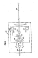
- Fig. 1 is a schematic diagram of an aerosol particle charge and size analyzer according to the principles of the present invention.
- Fig. 2 is a cross-section of the relaxation chamber of the analyzer shown in Fig. 1.
- Fig. 3 is a perspective view showing the intersection of two light beams from Fig. 1 to form a sensing volume.
- Fig. 4 is an enlarged perspective view of the sensing volume of Fig. 3, shown partially cut-away.
- Fig. 5 is a functional block diagram of signal processing circuitry according to the principles of the present invention for use with the analyzer of Fig. 1.
- Fig. 6 is an electrical circuit diagram showing the mixer of Fig. 5.
- Fig. 7 is a functional block diagram showing the signal processor of Fig. 5.
- Figs. 8A and 8B are electrical circuit diagrams showing the signal processor of Fig. 7.
- Fig. 9 is an electrical diagram of the size counter of Fig. 5.
- Fig. 10 is an electrical diagram of the charge counter of Fig. 5.
- Fig. 11 is a schematic diagram of a large particle measurement portion of an embodiment of the present invention.
- Fig. 12 is a schematic diagram of a small particle measurement portion of the embodiment shown in Fig. 11.
- Fig. 13 is a functional block diagram of an acoustic transducer drive circuit for use in the embodiment shown in Fig. 11.
- Fig. 14 is an electrical circuit diagram of the acoustic drive shown in Fig. 13.
- Fig. 15 is a functional block diagram of an acoustic transducer drive for use with the embodiment shown in Fig. 12.
- Fig. 16 is an electrical circuit diagram of the acoustic drive shown in Fig. 15.
- Fig. 17 is a plan view of an optical system for a variable range embodiment of the present invention.
- Fig. 18 is a plan view of the optical system of Fig. 17 including a removable optical mount.
- An aerosol particle charge and size analyzer is shown in Fig. 1 generally at 10. The device includes a
laser 12. an acousto-optic modulator 14, abeam focusing apparatus 16, arelaxation chamber 18. a scatteredlight focusing apparatus 20, and aphotodetector device 22. More specifically, thelaser 12 generates amonochromatic light beam 24, which is preferably polarized. Thelaser beam 24 is passed through an acousto-optic modulator, orBragg cell 14, which produces several diverging light beams each coherent with the other beams but differing in optical frequency. Two of the diverginglight beams prism 30. The other diverging light beams are not used and, therefore, are removed such as by an aperture or beam stops (not shown). The twolight beams -
Mirrors 32 and 34 in conjunction withlens 36 are used to focus the twobeams relaxation chamber 18. As thebeams volume 38 through which particles pass for measurement. The measuringvolume 38 is located between first and secondacoustic transducers electrode transducers - As particles pass through the measuring
volume 38 they scatter the light from thebeams lenses photodetector device 22. Aphotomultiplier 56 is used to detect thescattered light 48. - The unscattered light from
beams volume 38 is no longer needed and, thus, is blocked by beam stops 58 and 60, respectively. - A
laser 12 which has been used in the present device is a Spectra Physics Argon ion laser Model 164-06 which has been tuned to operate in a single frequency mode at a wavelength of 0.514 microns. The beam is vertically polarized upon leaving the laser housing. Helium-Neon lasers are less expensive and more portable and may be used in lieu of Argon ion lasers. - The
light beam 24 is fed into a Crystal Technology Acousto-optic modulator Model 3110 which produces light beams shifted in frequency by 40 MHz. - Fig. 2 shows the
relaxation chamber 18 in more detail. Therelaxation chamber 18 includes aninlet tube 62 through whichaerosol particles 64 are drawn and anoutlet tube 66 connected to a controlledvacuum system 68 which creates a slight negative pressure in the interior 70 of thechamber 18. The negative pressure causes theaerosol particles 64 to be drawn into the chamber interior 70. - An aerosol flow stream is established by the
inlet tube 62 which is mounted concentrically within asheath air tube 72 through which a sheath of clean air is fed after being filtered byparticle filter 74. The sheath airflow rate is controlled by using a positive pressure air flow source (not shown) to control the residence time ofindividual particles 76 within the measuringvolume 38. The light beams 26 and 28 which form the measuringvolume 38 are admitted into therelaxation chamber 18 through windows (not shown). - The
acoustic transducer 40 generates standing wave acoustic field within thechamber 18 perpendicular to the direction of flow of thesample aerosol 64. Acoustic absorbing material 78 is mounted on theinterior walls 80 of thechamber 18 to reduce reflections from thewalls 80, which are preferably of metal. The gas in which theaerosol particles 64 are suspended is moved sinusoidally within thechamber 18 by the acoustic field. A second, passiveacoustic transducer 42 is used to monitor the acoustic field, It is alos foreseen to monitor the driving signals of theactive transducer 40 to determine the acoustic field, although this is a less accurate way of determining the motion of the gas. - Viscous forces cause the particles of the
aerosol 64 to attempt to follow the motion of the gas. Due to the inertia of the particles, their motion lags behind that of the gas and has a lower amplitude. The phase lag and the relative amplitude reduction of a particle's motion with respect to the gas are functions of the aerodynamic diameter of the part cle for various frequencies of the acoustic field. A measure of e ther the phase or the amplitude (displacement or velocity) of a particle's motion relative to that of the surrounding gas can be used directly to calculate the aerodynamic diameter of the particle. Equations for this calculation are as follows:
- Ug is the peak velocity of the gas,
- ω is the angular acoustic frequency,
- <p is the relative phase difference between the motion of the particle and the motion of the gas. rp is known as the "relaxation time" of the particle and is given by:

- The aerosol is also subjected to a pulse of high voltage electric field generated by the
electrodes electrodes electrodes transducers volume 38. - The maximum velocity reached by a particle having an electrical charge q in an electrical field of strength Es is given by:

- A particle's motion transverse to the flow direction is a superposition of a unidirectional drift due to the applied electric field during the duration of the pulse and an oscillatory motion due to the acoustic field. A measure of the drift velocity VE due to the electric field can, hence, be used to calculate the charge, q, on the particle. provided the electric field strength Es is known, and the aerodynamic diameter da of the particle is determined from the particle's motion due to the acoustic field.
- A DC pulse is applied to the
electrodes - The measuring
volume 38 is defined by the region of intersection of the twolaser beams beams dark planes 82 in the measuringvolume 38. As a particle moves through the measuringvolume 38. the intensity of light scattered from the particle depends on its position relative to the bright anddark planes 82. Theplanes 82 bisect the angle of intersection of the light beams 26 and 28 and, thus, are aligned parallel to the direction of flow of the aerosol through thechamber 18 and perpendicular to the electric and acoustic fields. Hence, motion of a particle caused by these fields causes variations in the intensity of the light scattered by it but motion of the particle in the flow stream does not. Proper alignment of thebeams - The
defracted beam 28 from the acousto-optic modulator 14 is shifted in frequency from theundefracted beam 26. This results in a unidirectional motion of the bright anddark planes 82 at the modulation frequency fo of themodulator 14. Hence, the optical signal at thephotodetector 56 due to light scattered from the particle has a frequency fs given by:
- where fE = VE/df is the drift frequency due to the electric field,
- fao = Vp/df is the maximum signal frequency change due to the acoustic drive,
- fa = the acoustic drive frequency.
- df is the spacing between the bright lines of the laser beam interference pattern in the measuring
volume 38 and is given by:
laser beams volume 38 and λ is the optical wavelength of the laser light. The intensity of the light in thelaser beams - The sinusoidal portion of this signal is isolated from the carrier frequency (fo + fE) by electronic frequency demodulation techniques. The phase, or amplitude, of the sinusoidal portion has been compared in a microprocessor to that known for a size calibration particle and then to a precalculated look-up table so that an aerodynamic diameter can be assigned to the particle.
- The frequency fE due to the electric field acting on a charged particle is found by measuring the average period Ts of cycles of the Doppler signal occurring an integral number of acoustic cycles and comparing this measurement to the
carrier period 1/fo. Thus FE is given by: - fE = (1/Ts) -fo.
- The drift velocity is given by VE = df fE and the charge q on the particle is then determined from equation (4). The measurement is performed only when the applied field electric attains a quasi-steady value and the particle attains the quasi-steady migration, or drift, velocity. The polarity of the electrical field is reversed during each subsequent pulse in the preferred embodiment and, as a result, the precipitation loss is minimized.
- A single charged aerosol particle, traversing the measuring
volume 38 and being driven by the acoustic and electric fields, produces an FM signal burst at the output of thephotomultiplier tube 56. The FM carrier frequency is the LDV bias frequency plus the frequency associated with the electrical mobility of the particle and the modulation side bands are produced by sinusoidal particle motion. As shown in Fig. 5. the current produced at the output of thephotomultiplier tube 56, is fed into amixer 84, and is heterodyned, or mixed, to produce a two MHz FM signal burst for further processing. - The FM signal is demodulated by a phase-locked loop based
signal processor 86. The ouput of thesignal processor 86, which represents the instantaneous velocity of an aerosol particle, is passed through a bandpass filter and then converted into a pulse train by a high speed comparator (see Fig. 7). The signal is then applied to asize counter 88 and to acharge counter 90. The output signals from thesize counter 88 and thecharge counter 90 are fed into amicroprocessor 92, which computes both the size and charge for each particle. The size and charge information for each particle is stored by themicroprocessor 92. Once the desired amount of data is collected, the size and/or the charge distribution of the tested aerosol can be plotted by using aninterface 94 which connects themicroprocessor 92 to amicrocomputer 96, such as a desk top microcomputer, that may optionally include a printer 98 aplotter 100 and adisk drive 102. An example of aphotomultiplier tube 56 for use with the present device is a Hamamatsu side-on type photomultiplier tube, model R928. - Figure 6 shows the
mixer 84 which converts the 41 MHz laser Doppler burst recovered from thephotomultiplier tube 56 to a 2 MHz IF frequency. Themixer 82 consists of a three stage tuned amplifier portion 104, a 39 MHzlocal oscillator 106, amixer stage 108 and abuffer 110. Each stage of theamplifier 104, as well as themixer stage 108 andbuffer 110, consists of a dual-gate insulated-gate field-effect transistor (IGFET) 112, model 3N187, and its biasing circuitry. - Figure 7 shows the
signal processor 86 which receives the two MHz signal from themixer 84 and demodulates it to eliminate the 2 MHz carrier. The signal processor circuit includes the following: a three stage tunedamplifier limiter 120 and a phase lockedloop 122. The output of the phase locked loop represents the instantaneous velocity of the particle and is fed through anamplifier 124, aband pass filter 126. and then to ananalog gate 128. - An RF
threshold level detector 130 determines whether the output signal of theamplifier stage 118 exceeds a predetermined threshold level, and, if so, triggers theanalog gate 128 throughlead 132 to allow the signal processing sequence to continue is in aloop 132 which also feeds theanalog gate 124. If the amplitude of the RF signal fromamplifier 118 is greater than the selected level, the particle velocity, or recovered, signal is gated-through theanalog gate 128 to anamplifier 134 and aband pass filter 136. In this manner low level, unwanted signals are rejected. - The
second amplifier 134 and theband pass filter 136 are followed by asecond analog gate 138 and by a recoveredsignal detector 140. If the velocity, or recovered, signal is of sufficient amplitude, it is gated through theanalog gate 138 to abuffer 144 and azero crossing detector 146, where the sinusoidal signal is changed to a pulse train of 5 volt square waves. - A reference signal, which is received at an
input 148 from theacoustic transducer 42, is amplified byamplifier 150 and then passed through a two-stagephase shifting circuit crossing detector 156 converts the reference signal into a 5 volt square wave pulse train, similar to that of the recovered signal. The reference pulse train and the recovered pulse train are then fed to aphase detector 158, in the form of an exclusive OR gate. The resulting output is a square wave whose frequency is twice that of the reference signal or the recovered signal. The pulse width of this square wave is the phase difference between the recovered signal and the reference signal. The phase difference signal is gated to thesize counter 88 atlead 160 by a controltiming logic unit 162 throughgate 164. - The circuitry for the
signal processor 86 is shown in more detail in Figs. 8A and 8B. - The
size counter 88 is shown in Fig. 9 and includesinputs signal processor 86 over which the phase difference signal and the recovered velocity signal are fed. Thesize counter 88 translates this pulse width into a particle size measurement. Thesize counter 88, in conjunction with the rest of the signal processing circuitry, distinguishes particle motion due to the acoustic field from motion due to the electric field. - A measure of the duration of the phase difference pulses is accomplished by a 16 bit
binary ripple counter 166 that is normally held in the reset condition and is activated by the detection of an RF signal onlead 142. Anoscillator 168, such as a 12.416 MHz oscillator, is gated byNAND gate 170 and NOR gate 172 to aclock input 174 of thecounter 166 which produces a count that is proportional to the duration of the phase difference pulse. The phase lag count is fed throughtri-state buffers 176 and then to themicroprocessor 92 overdata bus 178. In a preferred embodiment, four such phase lag counts are accumulated and the average is found for increased accuracy. Alead 180 connects thesize counter 88 to thecharge counter 90. - A charged particle moving within the measuring
volume 38 will be attracted or repelled by an electric field, resulting in a frequency shift in the RF signal received by thephotomultiplier 56. Thecharge counter 90 shown in Fig. 10 measures this frequency shift from the 2 MHz center frequency so that the number of charges on a particle can be determined. - The 2 MHz RF subcarrier signal is received from the
signal processor 86 overlead 184, whileleads size counter 88. The 2 MHz signal is shaped into a square wave by acomparator 186. When a signal is received overlead 180, indicating that a particle is in the measuring volume, the output of a 40MHz TTL oscillator 188 is gated to a fourstage ripple counter 190 bygate 192. At the same time, the RF signal is gated to a threestage counter 194 bygate 196. After 1024 zero crossings of the 2 MHz carrier, thegate 192 is closed. The number resulting on thecounter 190 represents the period of the 2 MHz RF subcarrier. The value of the unshifted carrier is subtracted from the resulting number oncounter 190 to give a net frequency shift, which represents the particles electric mobility, or charge, when the diameter of the particle is known.Tri-state buffers 198 interface with themicroprocessor 92 over data bus 200. Control logic is provided to synchronize data access. - Appendix A lists software programs used with the present device to control its operation. Portions of the program enable a user to control the operation of the present device to take data, to display the data, to print the data, or to transfer the data to a disk drive system, as well as to plot the aerosol size and charge distributions and to produce three dimensional representations of the charge and size distribution of the sampled aerosol.
- In a preferred embodiment the device operates by assigning a plurality of channels to the particle size detection circuitry and, upon determining a particle's size, the size information is placed into one of the channels corresponding to the approximate size of a particle. Thus, recalculation of the size formula is avoided for each particle speeding up the analyzing process.
- The present device can be used to detect and analyze in real time up to 100 particles per second. Even faster particle detection rates are possible by keeping the polarity of the voltage pulses constant from one pulse into the next instead of alternating the polarity of the pulses. At higher rates, however, there is a greater likelihood of coincidence errors, caused by more than one particle in the measuring
volume 38. - The present device can also be used to determine particle concentrations within an aerosol by dividing the total number of particles counted by the run time and effective sample rate in units of flow.
- The present device can analyze particles of a predetermined size range as determined by a number of parameters. By varying these parameters, the size range in which the present analyzer will operate can also be varied. For instance, for a particular angle of intersection of the two
light beams volume 38 is determined. By changing the angle of intersection of the twolight beams - One embodiment of the present device includes the feature of simultaneous dual range particle size analyzation. A first, or large particle,
portion 202 of this embodiment is shown in Figure 11 and asmall particle portion 204 is shown in Fig. 12. Thefirst portion 202 includes amonochromatic laser 12 that has a wavelength of 488 nanometers and a power output that is variable from 100 to 800 milowatts. Thelight beam 24 is reflected by a pair ofmirrors optic modulator 14 which provides a second beam shifted in frequency of 40 MHz. The two beams are then deflected by amirror 210 into a doveprism beam splitter 212 which produces two pairs of beams, one pair for each particle size range. Other types of beam splitters, such as a standard cube or dielectric beam splitter, are also contemplated for use in the present device. - The
first beam pair portion 202 of the present embodiment are incident on a bi-mirror prism 214, the apex of which is centered midway between thebeam pair beams mirrors second mirror pair bi-mirror prism 228. Upon reflection from the secondbi-mirror prism 228 thebeams first relaxation chamber 230. - For measurement of large particles, the angle of intersection of the
beams beams beam stop 232 is placed in the paths of thebeams lens pair 234 and 236 through anaperture 238 to afirst photomultiplier 240. - Figure 12 shows the second portion, or
small particle portion 204, of the present two range embodiment. Asecond beam pair prism beam splitter 212 and then reflected by amirror 246 onto abi-mirror prism 248, as above. A pair ofmirrors second beam pair second relaxation chamber 254. - The scattered light caused by particles within the measuring volume is collected by a
second lens pair microscope objective 260 through anaperture 262 to asecond photomultiplier 264. Thus, a single light source can drive a two chamber analyzer for analyzing particles in two different size ranges. - Not only must the angle of intersection of the light beams change for different particle sizes but also the frequencies of the acoustic transducers (not shown) within the
relaxation chamber relaxation chambers - Figure 13 shows an acoustic drive used to drive an acoustic transducer at a frequency of 1 kHz. The one kHz. driver includes a 100 kHz.
oscillator 266 which feeds a pair of divide by 10circuits shaping circuit 272, abuffer 274 and aband pass filter 276 before being connected to a first active transducer in thelarge particle portion 202. A sinusoidal 1 kHz. acoustic field is thus produced by the first acoustic transducer. - Figure 14 is a circuit diagram of the 1 kHz. portion of the circuit of Figure 13. The
oscillator 266 is shown feeding the divide by 10circuits wave shaping circuit 272 in the form of an opamp feeds thebuffer 274 which in turn feeds the three stage band-pass filter 276. The second acoustic driver shown in Figure 15 includes a 240 kHz.oscillator 278 which feeds a divide by 10circuit 280, awave shaping circuit 282, and then anamplifier 284. This acoustic driver produces a 24 kHz. signal to drive the second active acoustic transducer in thesecond relaxation chamber 254 for particles of smaller sizes. The circuit diagram of the 24 kHz. driver circuit is shown in Fig. 16. - The above described two particle-size range analyzer operates for particle sizes from 0.2 to 20 micrometers in diameter. The large
particle measuring portion 202, shown in Figure 11 generates interference fringes spaced at approximately 12.0 micrometers and is able to analyze particles in the size range from 2.0 to 20.0 micrometers. Thesecond portion 204 of this embodiment generates interference fringes spaced at approximately 1 micrometer so that particles in the range of 0.2 to 6.0 micrometers in diameter can be analyzed. A wide range of particle sizes thus can be analyzed simultaneously in a device having a dual relaxation chambers and a single laser light source. The laser light beam is split into a first sensing pair for large particles and into a second sensing pair for small particles. Each sensing pair of light beams is focused to form measuring volumes within respective relaxation chambers with respective frequency acoustic fields. It is foreseen to apply this concept to a extend the range of particle sizes which can be analyzed by the present device such as by forming additional chambers. It is also foreseen to vary the sensing parameters in the present device in order to improve sensitivity to a particular particle size or to increase the size range on which the present device operates. - Figure 17 shows a preferred embodiment of
beam focusing apparatus 286. A plurality of diverginglight beams 288 are shown which were generated by the acousto-optic modulator 14. All but two of thebeams aperture 294 mounted at the edge of abase plate 296. On thebase plate 296 is mounted a mirroredprism 298, as well asmirrors lens 304 focuses thelight beams volume 306. An additional mirroredprism 308 is provided on thebase plate 296, as areholes 310 and 312 and bearing V-slot 314, the importance of which will become apparent by examining Figure 18. - Figure 18 shows the
beam focusing apparatus 286 including a removableoptical mount 316. The removableoptical mount 316 includes twoadditional mirrors beams optical mount 316 can be removed and repositioned without changing the location of the measuringvolume 306, yet the fringe spacing is changed. - Accurate repositioning of the removable
optical mount 316 is achieved by a three point kinamatic support system. Threescrews plate 316, each with a steel ball bearing (not shown) set on the end. A first bearing sits in thebearing hole 310 in thebase plate 296; the second bearing sits in the V-slot 314 in thesame base plate 296 for repositioning rotational orientation; and the third bearing sits directly on top of thebase plate 296. The removableoptical mount 316 is then spring mounted by spring loaded mountingbolt 328 to threaded hole 312 to thebase plate 296. The threescrews removable amount 316 parallel to thebase plate 296 before themirrors Lock nuts light beams - Although modifications and changes may be suggested by those skilled in the art, it is the intention of the inventors to embody within the patent warranted hereon all changes and modifications as reasonably and properly come within the scope of their contribution to the art.
Claims (18)


Applications Claiming Priority (2)
| Application Number | Priority Date | Filing Date | Title |
|---|---|---|---|
| US765144 | 1985-08-13 | ||
| US06/765,144 US4633714A (en) | 1985-08-13 | 1985-08-13 | Aerosol particle charge and size analyzer |
Publications (3)
| Publication Number | Publication Date |
|---|---|
| EP0214769A2 true EP0214769A2 (en) | 1987-03-18 |
| EP0214769A3 EP0214769A3 (en) | 1988-01-13 |
| EP0214769B1 EP0214769B1 (en) | 1992-05-06 |
Family
ID=25072766
Family Applications (1)
| Application Number | Title | Priority Date | Filing Date |
|---|---|---|---|
| EP86306194A Expired - Lifetime EP0214769B1 (en) | 1985-08-13 | 1986-08-11 | Aerosol particle charge and size analyzer |
Country Status (5)
| Country | Link |
|---|---|
| US (1) | US4633714A (en) |
| EP (1) | EP0214769B1 (en) |
| JP (1) | JPS63118634A (en) |
| CA (1) | CA1282160C (en) |
| DE (1) | DE3685175D1 (en) |
Cited By (2)
| Publication number | Priority date | Publication date | Assignee | Title |
|---|---|---|---|---|
| WO1989004482A1 (en) * | 1987-11-02 | 1989-05-18 | Stephan Dymling | Acoustic method for measuring properties of a mobile medium |
| GB2358703A (en) * | 1999-09-28 | 2001-08-01 | Microtrac Inc | An optical system for determining particle size distribution |
Families Citing this family (36)
| Publication number | Priority date | Publication date | Assignee | Title |
|---|---|---|---|---|
| GB8617568D0 (en) * | 1986-07-18 | 1986-08-28 | Clift R | Measurement of size of particles entrained in gas |
| KR970000633B1 (en) * | 1986-09-30 | 1997-01-16 | 컬로이들 다이나믹스 피티와이. 리미티드 | Method and apparatus for measuring particle size and charge amount |
| JPS63302342A (en) * | 1987-06-01 | 1988-12-09 | Agency Of Ind Science & Technol | Instrument for measuring configuration of particle in gas |
| US4948257A (en) * | 1987-09-14 | 1990-08-14 | Tsi Incorporated | Laser optical measuring device and method for stabilizing fringe pattern spacing |
| EP0359681B1 (en) * | 1988-09-15 | 1995-11-08 | The Board Of Trustees Of The University Of Arkansas | Characterization of particles by modulated dynamic light scattering |
| US5245290A (en) * | 1989-02-27 | 1993-09-14 | Matec Applied Sciences, Inc. | Device for determining the size and charge of colloidal particles by measuring electroacoustic effect |
| JP2962819B2 (en) * | 1990-11-30 | 1999-10-12 | キヤノン株式会社 | Displacement measuring device |
| US5156802A (en) * | 1991-03-15 | 1992-10-20 | The Babcock & Wilcox Company | Inspection of fuel particles with acoustics |
| US5383024A (en) * | 1992-08-12 | 1995-01-17 | Martin Marietta Energy Systems, Inc. | Optical wet steam monitor |
| US5296910A (en) * | 1992-10-05 | 1994-03-22 | University Of Akransas | Method and apparatus for particle analysis |
| JP2938327B2 (en) * | 1993-12-06 | 1999-08-23 | シャープ株式会社 | Measuring device for toner charge |
| US5922976A (en) * | 1995-10-12 | 1999-07-13 | California Institute Of Technology | Method of measuring aerosol particles using automated mobility-classified aerosol detector |
| JP3086873B2 (en) * | 1998-08-04 | 2000-09-11 | 工業技術院長 | Particle size distribution measuring method and device |
| WO2000025109A1 (en) * | 1998-10-28 | 2000-05-04 | Scofield Dillon F | Electrodynamic particle size analyzer |
| US6094266A (en) * | 1999-01-22 | 2000-07-25 | Honeywell Inc. | Detector for determining particle size distribution in an oscillating flow field |
| US6408704B1 (en) | 1999-02-01 | 2002-06-25 | Klaus Willeke | Aerodynamic particle size analysis method and apparatus |
| IT1311771B1 (en) * | 1999-02-24 | 2002-03-19 | Giorgio Bergamini | PERFECTED GAS FLOW METER WITH ULTRASOUNDS BASED ON PARABOLIC MIRRORS. |
| US7006682B1 (en) * | 1999-09-09 | 2006-02-28 | Nec Corporation | Apparatus for monitoring particles and method of doing the same |
| US6781118B2 (en) * | 2001-01-17 | 2004-08-24 | California Institute Of Technology | Particle charge spectrometer |
| GB0216549D0 (en) * | 2002-07-16 | 2002-08-28 | Univ Brunel | Method and system for measuring aerosol discharge |
| FR2842606B1 (en) * | 2002-07-18 | 2004-10-15 | Univ Claude Bernard Lyon | METHOD AND DEVICE FOR DETECTING THE PRESENCE OF LOADS ON THE SURFACE OF THE PARTICLES OF AN AEROSOL |
| US7053783B2 (en) | 2002-12-18 | 2006-05-30 | Biovigilant Systems, Inc. | Pathogen detector system and method |
| US7342660B2 (en) * | 2003-09-25 | 2008-03-11 | Deka Products Limited Partnership | Detection system and method for aerosol delivery |
| US7181952B2 (en) * | 2003-12-11 | 2007-02-27 | Fm Global Technologies, Llc | Characterization of mist sprays using a phase-doppler particle analyzer and an iso-kinetic sampling probe |
| US7430046B2 (en) | 2004-07-30 | 2008-09-30 | Biovigilant Systems, Inc. | Pathogen and particle detector system and method |
| EP1907818A4 (en) | 2005-07-15 | 2012-03-14 | Biovigilant Systems Inc | Pathogen and particle detector system and method |
| US7516019B2 (en) * | 2005-07-29 | 2009-04-07 | The Regents Of The University Of California | Method for online measurement of ultrafine aggregate surface area and volume distributions |
| US7782462B2 (en) * | 2006-11-27 | 2010-08-24 | Applied Nanotech Holdings, Inc. | Sono-photonic gas sensor |
| US8628976B2 (en) | 2007-12-03 | 2014-01-14 | Azbil BioVigilant, Inc. | Method for the detection of biologic particle contamination |
| DE102013202423A1 (en) * | 2013-02-14 | 2014-08-14 | Siemens Aktiengesellschaft | Detector for detecting particles in gas of measuring chamber during semiconductor manufacturing process, has pair of electrodes arranged in measuring chamber for generating electric field along gas flow direction |
| US11020057B2 (en) * | 2016-02-12 | 2021-06-01 | Qualcomm Incorporated | Ultrasound devices for estimating blood pressure and other cardiovascular properties |
| WO2018063144A1 (en) * | 2016-09-27 | 2018-04-05 | Halliburton Energy Services, Inc. | Systems and methods for volume concentration determination with diffraction of electromagnetic radiation |
| RU2652662C1 (en) * | 2017-06-14 | 2018-04-28 | федеральное государственное бюджетное образовательное учреждение высшего образования "Донской государственный технический университет", (ДГТУ) | Device for definition of distribution of weighed particles by mass |
| RU2652654C1 (en) * | 2017-06-14 | 2018-04-28 | федеральное государственное бюджетное образовательное учреждение высшего образования "Донской государственный технический университет", (ДГТУ) | Method of determination of distribution of weighed particles by mass |
| RU2763129C1 (en) * | 2021-06-02 | 2021-12-27 | Федеральное государственное бюджетное учреждение "33 Центральный научно-исследовательский испытательный институт" Министерства обороны Российской Федерации | Device for measuring the specific charge of aerosol particles |
| EP4303561A1 (en) | 2022-07-04 | 2024-01-10 | ETH Zurich | Device and method for the determination of the size and electric charge distribution of an ensemble of particles |
Family Cites Families (3)
| Publication number | Priority date | Publication date | Assignee | Title |
|---|---|---|---|---|
| US3208286A (en) * | 1962-08-02 | 1965-09-28 | Joseph D Richard | Particle size analyzer |
| US3763428A (en) * | 1971-11-26 | 1973-10-02 | Varian Associates | Simultaneous measurement of the size distribution of aerosol particles and the number of particles of each size in a flowing gaseous medium |
| DE3104878A1 (en) * | 1981-02-11 | 1982-08-19 | Natalija Georgievna Moskva Bulgakova | Method and device for analysing dispersed aerosol compositions |
-
1985
- 1985-08-13 US US06/765,144 patent/US4633714A/en not_active Expired - Lifetime
-
1986
- 1986-08-11 EP EP86306194A patent/EP0214769B1/en not_active Expired - Lifetime
- 1986-08-11 DE DE8686306194T patent/DE3685175D1/en not_active Expired - Lifetime
- 1986-08-12 CA CA000515782A patent/CA1282160C/en not_active Expired - Lifetime
- 1986-08-13 JP JP61190383A patent/JPS63118634A/en active Granted
Cited By (2)
| Publication number | Priority date | Publication date | Assignee | Title |
|---|---|---|---|---|
| WO1989004482A1 (en) * | 1987-11-02 | 1989-05-18 | Stephan Dymling | Acoustic method for measuring properties of a mobile medium |
| GB2358703A (en) * | 1999-09-28 | 2001-08-01 | Microtrac Inc | An optical system for determining particle size distribution |
Also Published As
| Publication number | Publication date |
|---|---|
| US4633714A (en) | 1987-01-06 |
| EP0214769B1 (en) | 1992-05-06 |
| JPH0346778B2 (en) | 1991-07-17 |
| JPS63118634A (en) | 1988-05-23 |
| EP0214769A3 (en) | 1988-01-13 |
| CA1282160C (en) | 1991-03-26 |
| DE3685175D1 (en) | 1992-06-11 |
Similar Documents
| Publication | Publication Date | Title |
|---|---|---|
| EP0214769B1 (en) | Aerosol particle charge and size analyzer | |
| US5296910A (en) | Method and apparatus for particle analysis | |
| US4778593A (en) | Method and apparatus for discriminating minute particles | |
| US5471299A (en) | Apparatus and method for the analysis of particle characteristics using monotonically scattered light | |
| US4251733A (en) | Technique for simultaneous particle size and velocity measurement | |
| Mazumder et al. | SPART analyzer: its application to aerodynamic size distribution measurement | |
| EP1855081B1 (en) | Means and methods for signal validation for sizing spherical objects | |
| US7087877B2 (en) | Auto focus for a flow imaging system | |
| US3835315A (en) | System for determining parameters of a particle by radiant energy scattering techniques | |
| Brown | Tutorial review: Simultaneous measurement of particle size and particle charge | |
| JPH0694596A (en) | Particle route determination device | |
| US5793478A (en) | Apparatus for measuring particle properties | |
| JPS6055776B2 (en) | Electrophoretic mobility measuring device | |
| US6553849B1 (en) | Electrodynamic particle size analyzer | |
| EP0213468B1 (en) | Apparatus and method for analyzing particles in a medium | |
| Lilienfeld et al. | Development of a prototype fibrous aerosol monitor | |
| US4477187A (en) | Apparatus and method for sizing particles | |
| US6281973B1 (en) | Optical detection system and method for determining particle size distribution in an oscillating flow field | |
| US7453569B2 (en) | Method and apparatus for measuring particle motion using scattered radiation | |
| Renninger et al. | Particle sizing by electrical single particle aerodynamic relaxation time analyzer | |
| GB2264556A (en) | Diffraction analysis of particle size, shape and orientation | |
| RU2006824C1 (en) | Method of analysis of impulse pairs in photoelectric aerosol counters | |
| Hemsley et al. | The use of calibration techniques for the development and application of optical particle sizing instruments | |
| SU1451589A1 (en) | Apparatus for analysis of heterogeneous particles produced in grinding process | |
| Ruck et al. | Particle‐Induced Limits of Accuracy in Laser Doppler Anemometry |
Legal Events
| Date | Code | Title | Description |
|---|---|---|---|
| PUAI | Public reference made under article 153(3) epc to a published international application that has entered the european phase |
Free format text: ORIGINAL CODE: 0009012 |
|
| AK | Designated contracting states |
Kind code of ref document: A2 Designated state(s): CH DE FR GB LI NL |
|
| PUAL | Search report despatched |
Free format text: ORIGINAL CODE: 0009013 |
|
| AK | Designated contracting states |
Kind code of ref document: A3 Designated state(s): CH DE FR GB LI NL |
|
| 17P | Request for examination filed |
Effective date: 19880712 |
|
| 17Q | First examination report despatched |
Effective date: 19900404 |
|
| GRAA | (expected) grant |
Free format text: ORIGINAL CODE: 0009210 |
|
| AK | Designated contracting states |
Kind code of ref document: B1 Designated state(s): CH DE FR GB LI NL |
|
| REF | Corresponds to: |
Ref document number: 3685175 Country of ref document: DE Date of ref document: 19920611 |
|
| ET | Fr: translation filed | ||
| PLBE | No opposition filed within time limit |
Free format text: ORIGINAL CODE: 0009261 |
|
| STAA | Information on the status of an ep patent application or granted ep patent |
Free format text: STATUS: NO OPPOSITION FILED WITHIN TIME LIMIT |
|
| 26N | No opposition filed | ||
| PGFP | Annual fee paid to national office [announced via postgrant information from national office to epo] |
Ref country code: GB Payment date: 20000801 Year of fee payment: 15 |
|
| PGFP | Annual fee paid to national office [announced via postgrant information from national office to epo] |
Ref country code: FR Payment date: 20000830 Year of fee payment: 15 |
|
| PGFP | Annual fee paid to national office [announced via postgrant information from national office to epo] |
Ref country code: CH Payment date: 20000920 Year of fee payment: 15 |
|
| PGFP | Annual fee paid to national office [announced via postgrant information from national office to epo] |
Ref country code: DE Payment date: 20000929 Year of fee payment: 15 |
|
| PG25 | Lapsed in a contracting state [announced via postgrant information from national office to epo] |
Ref country code: GB Free format text: LAPSE BECAUSE OF NON-PAYMENT OF DUE FEES Effective date: 20010811 |
|
| PG25 | Lapsed in a contracting state [announced via postgrant information from national office to epo] |
Ref country code: LI Free format text: LAPSE BECAUSE OF NON-PAYMENT OF DUE FEES Effective date: 20010831 Ref country code: CH Free format text: LAPSE BECAUSE OF NON-PAYMENT OF DUE FEES Effective date: 20010831 |
|
| PGFP | Annual fee paid to national office [announced via postgrant information from national office to epo] |
Ref country code: NL Payment date: 20010831 Year of fee payment: 16 |
|
| GBPC | Gb: european patent ceased through non-payment of renewal fee |
Effective date: 20010811 |
|
| REG | Reference to a national code |
Ref country code: CH Ref legal event code: PL |
|
| PG25 | Lapsed in a contracting state [announced via postgrant information from national office to epo] |
Ref country code: FR Free format text: LAPSE BECAUSE OF NON-PAYMENT OF DUE FEES Effective date: 20020430 |
|
| PG25 | Lapsed in a contracting state [announced via postgrant information from national office to epo] |
Ref country code: DE Free format text: LAPSE BECAUSE OF NON-PAYMENT OF DUE FEES Effective date: 20020501 |
|
| REG | Reference to a national code |
Ref country code: FR Ref legal event code: ST |
|
| PG25 | Lapsed in a contracting state [announced via postgrant information from national office to epo] |
Ref country code: NL Free format text: LAPSE BECAUSE OF NON-PAYMENT OF DUE FEES Effective date: 20030301 |
|
| NLV4 | Nl: lapsed or anulled due to non-payment of the annual fee |
Effective date: 20030301 |