EP0214728B1 - Erkennungssystem - Google Patents
Erkennungssystem Download PDFInfo
- Publication number
- EP0214728B1 EP0214728B1 EP86305495A EP86305495A EP0214728B1 EP 0214728 B1 EP0214728 B1 EP 0214728B1 EP 86305495 A EP86305495 A EP 86305495A EP 86305495 A EP86305495 A EP 86305495A EP 0214728 B1 EP0214728 B1 EP 0214728B1
- Authority
- EP
- European Patent Office
- Prior art keywords
- labels
- output
- confidence
- data
- portions
- Prior art date
- Legal status (The legal status is an assumption and is not a legal conclusion. Google has not performed a legal analysis and makes no representation as to the accuracy of the status listed.)
- Expired - Lifetime
Links
Images


Classifications
-
- G—PHYSICS
- G10—MUSICAL INSTRUMENTS; ACOUSTICS
- G10L—SPEECH ANALYSIS TECHNIQUES OR SPEECH SYNTHESIS; SPEECH RECOGNITION; SPEECH OR VOICE PROCESSING TECHNIQUES; SPEECH OR AUDIO CODING OR DECODING
- G10L15/00—Speech recognition
Definitions
- This invention relates to a recognition system and in particular to systems for the recognition of waveforms. Particular applications of such systems include the recognition of speech waveforms or waveforms arising from any other physical process. Throughout this specification particular reference will be made to speech recognition systems. However, the present invention is equally applicable to other recognition problems.
- the original waveform to be recognized is one of sound pressure varying with time.
- This variation in amplitude may be represented electronically as, for example, a voltage level varying with time.
- the characteristic commonly studied in known speech recognisers is that of the variation of energy with frequency for successive short time segments of the waveform.
- Such a system is shown for example in European Patent Application 0086589 where the speech patterns to be recognised are a time series of frequency spectrum envelopes.
- Such spectrum transformation from a time domain to a frequency domain representation is used to derive spectrograms of unknown words which can then be correlated with the spectrograms of known words for recognition by choosing the reference spectrogram which is most similar to the unknown spectrogram.
- Such spectrograms can be obtained for example from a set of tuned filters whose outputs are sampled periodically thus producing a spectrogram of a particular time window of speech.
- spectrograms can be obtained for example from a set of tuned filters whose outputs are sampled periodically thus producing a spectrogram of a particular time window of speech.
- pre-emphasise the spectral content of the waveform by amplifying the signal by a factor which increases with frequency.
- the aim of such signal transformations is to improve the recognition performance of the overall system.
- information is also lost. For instance, the time ordering of events separated by periods less than the width of the transform window or the filter bank time constant are lost.
- the loss of such information has a detrimental effect on the recognition performance on waveforms which are only distinguishable by short transient events.
- Such spectrogram correlation methods are conventionally extended by detecting the peaks in energy called formants which can be observed in spectrograms.
- Spoken words are characterised by the pattern of energy peaks in the frequency-time domain, but as with phonemes, there is no definition of formants which is independent of word context or speaker. Moreover formants are extremely difficult to locate reliably in real speech.
- speech signals suffer from considerable variation between repetitions of the same utterance, and between utterances from different speakers of the same words. Such variations can occur in a variety of characteristics one example being the time duration of a word. This hampers conventional recognition systems which are unable to act independently of such variability.
- Non-linear variations in the duration of words are conventionally handled by allowing the spectrograms being correlated to stretch in time or frequency by a process known as Dynamic Time Warping (DTW).
- DTW Dynamic Time Warping
- Such methods have a large processing requirement and the consequently less specific matching process increases the likelihood of mismatches between similar sounding words e.g., pin, bin.
- a recognizing system comprising means for the input of electronic data to be recognized, decision means for outputting as electronic recognition signals labels corresponding to portions of said data and chosen from a reference set of labels wherein said decisions means comprises assignment means for assigning to each of successive portions of said data in dependence on said successive portions of data a plurality of labels from a reference set of labels and corresponding confidence measures indicating a degree of confidence in the correct assignment of each label; a plurality of buffer means each for storing values corresponding to a plurality of successive portions of data forming a one dimensional array said values comprising for each portion of data, timing information defining the position in time of the portion relative to others of said portions and one of said labels and the corresponding confidence measure assigned to the portion by said assignment means and each for containing labels having corresponding confidence measures of a predetermined rank relative to those of other labels assigned to the same portion of data, one of said buffer means being an output buffer means containing values whose corresponding confidence measures indicate the highest confidence in the correct assignment of the corresponding label of all
- Such an arrangement using a buffer for storing values in which labels have already been assigned to the portions of a one dimensional array before output decisions are made enables the system to operate continuously if required without any need for segmentation. Since the decision made by the output means depends on the relative magnitude of the confidence measures for adjacent portions rather than the absolute confidence measure in respect of each portion the system is less susceptible to being either too discriminatory or not discriminatory enough in locating recognised waveform portions whilst still being able to operate in a continuous fashion if required. Furthermore since the system may be operated continuously many recognition problems may be overcome by suitable selection of the length of the buffer particularly if a limited set of waveforms are to be recognized.
- the multiple buffers overcome additional recognition problems, particularly in the context of voice recognition where words have to be recognized which only differ in the presence or absence of endings.
- the arrangement enables in effect a decision about a particular portion of a waveform or other data to be postponed until it has been ascertained that other possible label assignments fulfil certain conditions and in this respect is generally applicable to other recognition problems which involve the recognition of electronic data.
- the portions of the waveform to be recognised which are adjacent overlap.
- the overlap may consist of an input shift register being read by feature detectors at each step of the input data through it so that the input shift register effectively comprises a window being scanned along a waveform through which a series of overlapping portions of the waveform are observed in turn.
- the present invention further comprises a feature matching device comprising a plurality of feature detectors arranged in operation to detect any occurrence in successive portions of said data of any of a plurality of respective features and said decision means is for outputting said labels in dependence on the features detected by said feature matching device in said successive portions and said assignment means is for assigning said labels and corresponding confidence measures in dependence on the features detected by said feature matching device in said successive portions.
- a feature matching device comprising a plurality of feature detectors arranged in operation to detect any occurrence in successive portions of said data of any of a plurality of respective features and said decision means is for outputting said labels in dependence on the features detected by said feature matching device in said successive portions and said assignment means is for assigning said labels and corresponding confidence measures in dependence on the features detected by said feature matching device in said successive portions.
- the output means in operation stores and delays outputting the recognition signals for a predetermined time if the confidence measures corresponding to the same sub-array of neighbouring portions stored in any other buffer means indicate an increase in the confidence of the correct assignment of any of their corresponding labels with time and replaces said stored recognition signals with any recognition signal subsequently recognised during said predetermined time having a confidence measure indicating a greater confidence in the correct assignment of the corresponding label than that of said stored signal and outputs the recognition signal in said store at the end of said predetermined delay.
- a signal is output if at the time the initial assignment is made there are no other less likely label assignments which are increasing in confidence. If there are any less likely label assignments which are increasing in confidence the initial signal is preferably stored and only output if none subsequently become more confidently assigned candidates for output than the initial signal before a predetermined length of time has elapsed. If the other initially confident assignments do become more confident that the initial assignment before the predetermined length of time has elapsed and are thus entered in the buffer containing the labels assigned with the highest confidence measures then they may preferably replace the initial stores signal and be output in preference to the initial label to be output providing the usual conditions for output are met. It is thus possible to correctly distinguish between waveforms and words differing only in their suffixes even though they may have common prefixes which in other system lead to premeature misrecognitions.
- the decision to output a signal from the output buffer means is preferably made in respect to those portions whose corresponding confidence measures in said output buffer means indicate a degree of confidence in the correct assignment of their corresponding labels which is greater than that indicated by each of the confidence measures in said output buffer means corresponding to a sub array of neighbouring portions in the array.
- the output means then in effect search for maxima in the confidence measures corresponding to the neighbouring portions in the array in the output buffer means.
- the maxima may be searched for only in respect of the immediately preceding and immediately succeeding portions to that to be output or with respect to several preceding and several succeeding portions in the array.
- Other suitable relationships between the confidence measures of portions in respect of which labels are to be output and those of their neighbouring portions in the array can be used as appropriate.
- the output means is for outputting electronic recognition signals if the label to be output has a corresponding confidence measure indicating a greater degree of confidence in its correct assignment than that of any of the labels corresponding to a predetermined number of succeeding portions in said array.
- This enables the rejection of false recognitions of adjacent portions of waveform.
- the number of succeeding portions of the array studied is preferably chosen so that it represents a time interval small compared to the duration of a spoken word or other waveform pattern to be recognised so that maxim corresponding to adjacent words are not confused.
- the buffer means function as one or more shift registers and tests on the confidence measures of said labels in said buffer means are conducted at the input to each buffer means and labels and timing information output from the output of the output buffer means if before the label to be output has reached the output no further confidence measure maxima greater than that to be output have been detected at the input of the output buffer means.
- Such an arrangement may in effect utilise the buffer shift register as the store for recognition signals to be output and as the timing device for deciding when the predetermined time has elapsed at the end of which the recognition signal is to be output from the store.
- the output buffer means should preferably only contain values for portions of data corresponding to a total time length less than the time duration of a waveform to be recognised.
- the input means includes an input buffer which functions as an input shift register comprising a series of cells through which said signal can be continuously passed, the contents of the buffer constituting a said temporal portion, and there is further provided a feature detection device operable to detect the presence of a plurality of predetermined features within a said portion; and said decision means comprises means for reading the feature detection device at steps of said signal through said register and comparing the readings for said features thus detected with predetermined reference vectors each having a corresponding label, and assigning that label whose reference factor most closely matches said readings together with a corresponding confidence measure to the portion of said signal which produced said readings.
- the input shift register contains data corresponding in time duration to at least the length of the longest waveform portion to be recognised and the labels are assigned at each step of said data through said input shift register. This facilitates operation of the system in a continuous and constructionally convenient manner.
- the input shift register may contain data corresponding in time duration to at least the length of the longest feature to be detected and the feature matching device may comprise a cumulative store in respect of each feature detector the content of said stores indicating whether a feature has been detected since the store was last cleared and the contents of the stores being compared with said reference vectors at each step of said data through said shift register and said cumulative stores being cleared after a predetermined time which is preferably after each a label is output from the system.
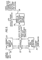
- FIG. 1 a schematic diagram of a waveform recognition system according to an embodiment of the present invention is shown.
- the signal in the form of a time domain waveform which in the case of speech waveform recognition could be obtained from a suitable microphone, is first passed through a low pass filter (1) to suppress aliasing effect.
- the signal is then sampled at a suitable rate and digitized (2).
- the use of a low pass filter is not essential though, unless aliasing destroys all the distinguishing information in the signal.
- the signal may then be normalised in energy by a conventional automatic gain control processing stage (3).
- This stage again is not essential and if the loudness of the signal is itself a distinguishing feature such energy normalisation may be omitted.
- the normalised signal is then passed to a feature matching device (4) which detects the presence or otherwise of a set of features in the waveform. During each sample period this device constructs a binary vector or list of feature occurrences detected and passes it to the decision circuit.
- the decision circuit (5) then analyses the successive feature lists and compares them during each sample period with a set of labelled reference feature lists each corresponding to a waveform to be recognised in order to identify the closest reference feature list or lists. Labels and confidence measures for the closest reference feature lists are then assigned and output together with information identifying the time of recognition to the syntactic processing device (6).
- the syntactic processing device (6) accepts a sequence of recognition labels and recognition times from the decision circuit. Labels are rejected if they conflict with the syntactic constraints of the recognition task. The device may substitute other labels if rules derived from contextual evidence permit.
- the feature matching device (4) in Figure 1 detects the presence or absence of a number of features in a time domain representation of the waveform to be recognised.
- the features comprise tests of amplitude all of which must be simultaneously satisfied for the feature to be present.
- Figure 2 shows such a feature (7) matching a waveform to two different positions.
- the tests are preferably of whether the amplitude of the signal is greater than a specific value at a specific time or less than a specific value at a specific time. However any other suitable such tests may be used for example the amplitude may be required to be within two or more limits.
- the times of the tests are specified relative to the times of the other tests comprising the feature.
- Each feature can consist of any number of such tests separated by fixed time intervals of any length. Generally the tests would preferably not include more than 5 such tests or extend over a time period longer than the duration of the longest waveform or word in the vocabulary to be recognised.
- the tests necessary to establish the presence or absence of the above features in the waveform to be recognised may be carried out in a number of ways using either analogue or digital circuitry.
- the tests are conducted using digital circuitry as shown in Fig. 1 in which a digitiser (2) is used.
- This is preferably achieved by passing the sampled and digitised waveform values down a shift register which is clocked in synchronism with the sample frequency.
- the system in effect studies a series of overlapping portions of the input waveform each portion being formed by the contents of the shift register.
- Each stage of the shift register thus contains one digital word corresponding to the amplitude of the corresponding sample of the waveform.
- a set of taps may then be taken from predetermined stages of the shift register test the values in the shift register stages to which they are connected.
- Feature detectors are connected to the taps to test for the combined presence of values which satisfy the conditions for a respective feature in the stages of the shift register to which the taps are connected.
- the time interval between the tests making up a feature corresponds to the spacing between the taps.
- the shift register is preferably at least as long as the time interval occupied by the longest feature.
- the waveform as it is passed down the shift register thus presents all possible time shifted versions to the feature detectors. If at any instant all the tests for any particular feature are found to be satisfied the feature is noted as being present.
- Many such feature detectors may be connected to the shift register and many taps corresponding to tests for a plurality of features may be connected to any one shift register stage. Multiple connections to shift register elements however, could lead to a high density of interconnect and difficulties in VLSI implementation.
- the connections for each feature do not need to overlap providing the detection delay corresponding to the spatial separation of the taps is compensated.
- taps to be connected via delay circuits to shift register stages other than those to which they would be connected if no delay circuits were used. Such a construction can be useful in a VLSI implementation where the number of connections to each shift register is preferably kept low.
- Test configurations for each feature are ideally chosen so that they appear in more than one class of waveform. This ensures that the recogniser extracts as much information from the input signal as possible and provides immunity to certain forms of noise.
- Conventional template matching systems seek only to obtain matches with single classes of patterns and suffer from an increasing error rate as the number of classes also increases.
- the selection of the test configurations for features may be carried out by trial and error or automatically using a suitable algorithm and the most suitable set of features will depend on the recognition task to be performed.
- the device may either construct a binary vector comprising a list of feature occurrences detected during that sample period alone and compare the list compiled with the reference set of feature lists or the device may construct a list of feature occurrences which is stored in a cumulative store which lists all those features which have been detected since the cumulative store was last cleared. In the latter case the store is preferably cleared after each recognition has occurred and been output from the system.
- the portion of waveform for which the sample feature lists are compiled are of constant time duration and are preferably the same length as that the input shift register corresponds to.
- the sample feature lists compiled are of increasing length and may be of longer duration than that the input shift register corresponds to.
- the comparator circuit (8) compares the sample feature list (9) whether it comes from a cumulative store in the feature matching device (4) or direct from the feature detectors of the feature matching device (4), at each step of the data through the input shift register, with a set of reference feature lists (10) each corresponding to a word in the system's vocabulary and then works out a confidence measure indicating the degree of confidence in the correct assignment of each label in the set to the corresponding portion of data.
- At least one reference feature list is labelled with the silence category and very low amplitude signals, noise or meaningless signals would tend to be assigned this label by the decision circuit.
- the measure of closeness taken is preferably the number of differences between the sample and the reference lists and may be computed very rapidly for a very large number of binary references for example by using the methods described in US patent number 4119946. In this case a low value of the smallest reference distance measure will signify a high value for the confidence of the corresponding label decision.
- Other suitable comparator means may of course be used to calculate other measures of the closeness and therefore confidence measures in the correctness of the assignment of the labels if required.
- the comparator outputs to a single output buffer (11) that label together with its corresponding confidence measure and an indication of the time of recognition which the comparator has found to have the reference feature list closest to the sample feature list, i.e. that having the highest confidence measure in the correctness of its assignment.
- a continuous series of assignments of labels and corresponding confidence measures are generated as the waveform passes through the system.
- the decision circuit preferably retains the last N label assignements with their corresponding timing information and confidence measures in the buffer (11).
- a maximum in the degree of confidence in the correct assignment of the labels and thus confidence measures (a confidence measure maxima) is found in the buffer which is preferably not exceeded by any of the N succeeding measures the corresponding label together with the time of the confidence measure maximum with which the label is associated are then output from the buffer by the decision circuit.
- N may be chosen so that it represents a time interval small compared to the duration of a spoken word of other waveform pattern so that maxima corresponding to adjacent words are not confused.
- the length of the buffer may correspond to the length of time corresponding to the last N label decisions or to a greater length of time and may operate as a shift register in which case the label to be output may be output from the end of the shift register if a maxima detector at the input to the buffer has not detected any greater maxima since that to be output and within N succeeding assignments.
- a maxima detector at the input to the buffer has not detected any greater maxima since that to be output and within N succeeding assignments.
- the maxima detector (12) analyses the confidence measures of in this case the three most recent labels entered into the output buffer (11) and looks for maxima. However the maxima detector could study a greater number of labels.
- N is set to be four or less then both the labels will be output by the detector (12) enabling the output enable (13) at the end of the output buffer shift register (11). If N is set to be greater than four then the higher confidence measure of the latter label (which is twenty two in contrast to eighteen for the former) will result in the latter label only being output when it reaches the end of the shift register.
- the comparator outputs labels and confidence measures for a plurality of the most confident class label assignments from the comparator means each to a separate buffer together with their confidence measures and timing information.
- the top 3 or 4 class choices are monitored and thus 3 or 4 buffers are used each containing respectively the 1st (11), 2nd (14), 3rd (15) and 4th (16) choice of label for any one sample period.
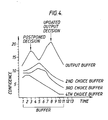
- the above difficulty might be manifest by the incorrect recognition of "polar” as “pole” followed by an unrecognisable segment.
- the problem is overcome by this embodiment of the present invention by postponing the "pole” decision if the confidence of one or more other class decisions (e.g. "polar, polarise") are detected to be rising at the same time that the "pole” recognition is made.
- the 2nd and 3rd choise buffers contain labels whose confidence measures are increasing at the time that the postponed decision to output label A corresponding to "pole” is made by the detection of the corresponding confidence maxima at time three. If the next candidate label for output (i.e.
- the next label having a confidence measure maxima, in this example label B corresponding to "polar" corresponded to a class whose confidence was rising at the time of the postponed decision, it would be output instead as an updated classification decision by the decision circuit (as will "polar" in this example at time eight).
- This decision would again be postponed if the same criterion applied as before (e.g. if the confidence measure for label C in the 3rd choice buffer were increasing at time eight when the maxima for "polar" was detected).
- the original postponed decision would be output (in this example the label C increases in confidence at times one to five but never reaches a value higher than those for labels A and B).
- a label would be considered to have a confidence measure which was rising if the confidence measures associated with that class of label at that time exceeded all those preceding it in the output buffer (14, 15 or 16) or if the confidence measure at that time satisfied some other gradient detection rule.
- the feature list should not be deleted following a decision which is to be postponed pending a possible update.
- the buffers however must correspond to a length of time at least as long as the predetermined time which one must wait before stopping the search for a better maxima than that already detected which can be used to update it.
- the buffers preferably operate as shift registers as shown in Fig.
- the label to be output is output from the end of the shift register containing the labels assigned with the highest confidence measures (the output buffer) (11) if a maxima and increase detector (12) at the input to that shift register has not detected any greater maxima since that of the initial output decision within N succeeding assignments and the initial output is not to be updated by being replaced by an output label which was found to be increasing in confidence in one of the other shift register buffers by the maxima and increase detector (12) when the initial output decision was made and which subsequently became a more likely candidate for output than the initial output label before the initial output label reached the output of the buffer.
- the output buffer For example in the case where two labels with confidence measure maxima which are to be output are in the output buffer but there was no label in any of the other buffers with a rising confidence measure at the time the initial output decision was made then both the labels in the output buffer are output.
- the volume of additional hardware in the decision circuit necessary to recognise words containing others within them depends upon the depth of nesting encountered. For most applications only the confidence measures and label decisions of the top 3 or 4 class choices need be monitored for upward gradients at any one time, and buffers for the most recent labels timing information and confidence measures for each of these class choices provided. In practice the buffers for the 2nd, 3rd and 4th choices need only be as long as is necessary to detect any increasing confidence measures at the time the initial output decision is made and thus need not be as long as the output buffer. If the output buffer is used as is shown in Figure 3 to store postponed decisions.
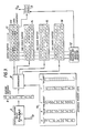
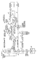
- the functional block diagram of a hardware embodiment of a particular waveform recognition system according to the present invention is shown in Figure 5.
- the hardware inputs waveform samples 20 into a shift register 21.
- Comparators 22 are used to detect the presence of features stored in memory 23, in the "window" of waveform data held in shift register 21.
- the features which are being searched for can be updated by changing the features stored in memory 23.
- the presence or absence of a match, signifying the presence or absence of the relevant features in the waveform data stored in shift register 21, is signalled to a further memory 26 which accumulates a record of which features have been detected in the sampled waveform.
- the results 27 of feature matching are output from memory 26 to the controlling computer.
- the memory 26 can be reset by the controlling computer on line 28 at the end of a sampling period-which may occur, in speech recognition applications, on detecting the end of a word.
- Figure 6 is an overall block diagram of the hardware.
- the hardware performs four distinct functions: storage for the last 256 waveform samples; storage to hold feature definitions; feature detection; and accumulative storage to register which features have been detected in the sampled waveforms since the store was last reset.
- each "feature” consists of one, two or three “elements” (instantaneous amplitudes each satisfying respectively perdetermined constraints) separated by a number of samples, it is possible to interleave a number of features within a memory device so that no two feature "elements” occur at the same sampling point. This concept is best explained with reference to Figure 7 which shows how three features which together comprise seven elements covering seven samples can be packed into nine consecutive locations in the feature definition RAM (the values in two of the locations being in determinate).
- This packing process enables the processing speed of the hardware to be increased by a factor of N over the software simulation, where N is the number of features effectively processed in parallel.
- the circuitry described here with reference to Figures 5, 6 and 8 uses approximately 60 readily available TTL and memory devices, and will process around 100 features effectively in parallel, giving an increase in speed of a factor of 100.
- the hardware may itself be extended or paralleled to yield further improvement in throughput.
- this hardware is of use in many pattern matching applications.
- One example, which is more fully detailed below, is that of character string matching with text data.
- the hardware described here could search for approximately 30 eight character words simultaneously at a rate greater than two full A4 pages of text per second.
- an "instantaneous" storage register 29 has one bit per feature; the sign of that bit indicating whether or not that feature is present in the current "snapshot" of the waveform. Initially, all these bits are set to "true” (i.e., feature present). All the feature elements held in RAM23 are sequentially compared, in comparator 22, with the corresponding waveform sample from RAM21 (which is configured as a shift register). If a feature element in RAM23 does not match the waveform sample, the bit in register 29 corresponding to that feature is set to "false”. After comparing all the elements from RAM23, the only bits in register 29 that remain set "true" correspond to the features that have matched the waveform sample.
- the result from the register 29 is passed to the "accumulative storage" RAM26 where a record of the features that have been matched is stored. This process is repeated for each new waveform input into RAM21, thus effectively scanning the waveform across all the features stored in RAM23.
- RAM23 By loading different values into RAM23 it is possible to search for different features or different combinations of featu res.
- the fast address counts from 0 to 255 between each new input sample.
- the slow address increments on each new sample.
- a count 36 is generated which configures a RAM22 effectively as a shift register.
- Each new waveform sample overwrites the oldest stored sample, thus forming a cyclic store of the most recent 256 samples.
- the input waveform is'seen to scan across all locations. This operation is illustrated by the following: (where 26 is the value of the new sample read in. The oldest sample of 108 has been "lost" off the end of the shift register).
- the comparator 37 compares the magnitude of two absolute 15-bit integers; one further bit from the feature RAM determines whether the magnitude of the feature element should be less than or greater than the waveform magnitude to generate a "true" output. Note that for the implementation of a character searching system only an equality condition is required from the comparator.
- the instantaneous storage consists of some pipelined circuitry. This is used to achieve the required cycle period. In effect the output results are delayed by one sample period, but the data throughput rate is maintained.
- the three way pipelined storage functions as follows:
- the result of the matching operation is returned to the host computer at 32 eight bit bytes. These represent which of the 256 features (theoretical maximum) have been present in the waveform since the accumulative storage was last reset. Bits correspoinding to features that have not been defined are simply ignored.
- the feature matching circuitry of Figure 8 may be adapted to implement a high speed character string search system. This is potentially very useful for text processing or database handling programs where speed is vital.
- the modification is simply to change the output of the comparator section of the hardware so that a "true" output is generated when the value of the data sample is precisely equal to the value of the feature element.
- the feature data is then replaced with the ASCII values (or whatever representation is being used) of the string to be searched, and the whole text is input, character by character through the data buffer (at 10KHz).
- each character By labelling each character with its associated string, several different strings may be searched for in one operation. Thus, up to 256 individual characters (equivalent to 32 8-character words) may be searched for in one pass.
- the data throughput rate is again 10KHz, which is equivalent to more than two full A4 pages of text per second.
- search system may contain "wildcard” characters simply by omitting characters in the relevant places.
- "wildcard” characters simply by omitting characters in the relevant places.
- An example of data loading to match the strings, "Thank you”, “pre”, and “hoo * " (where " * " signifies any character) would be: where string number 0 is the null string number, and X is any character.
- this circuitry is potentially very useful in keyword spotting for database applications. This includes searches for telephone numbers, car numbers, or parts thereof etc. It could also be useful for establishing which of a set of keywords are present in a corpus of text, perhaps for classification purposes. As shown above, searches for strings with wildcards/partial information are possible.
Landscapes
- Engineering & Computer Science (AREA)
- Computational Linguistics (AREA)
- Health & Medical Sciences (AREA)
- Audiology, Speech & Language Pathology (AREA)
- Human Computer Interaction (AREA)
- Physics & Mathematics (AREA)
- Acoustics & Sound (AREA)
- Multimedia (AREA)
- Measurement Of Mechanical Vibrations Or Ultrasonic Waves (AREA)
- Radar Systems Or Details Thereof (AREA)
- Holo Graphy (AREA)
- Optical Communication System (AREA)
- Iron Core Of Rotating Electric Machines (AREA)
- Measurement Of Current Or Voltage (AREA)
- Compression, Expansion, Code Conversion, And Decoders (AREA)
- Recording Measured Values (AREA)
- Measuring Or Testing Involving Enzymes Or Micro-Organisms (AREA)
- Electrophonic Musical Instruments (AREA)
Claims (14)
Priority Applications (1)
| Application Number | Priority Date | Filing Date | Title |
|---|---|---|---|
| AT86305495T ATE50468T1 (de) | 1985-07-16 | 1986-07-16 | Erkennungssystem. |
Applications Claiming Priority (2)
| Application Number | Priority Date | Filing Date | Title |
|---|---|---|---|
| GB858517918A GB8517918D0 (en) | 1985-07-16 | 1985-07-16 | Recognition system |
| GB8517918 | 1985-07-16 |
Publications (2)
| Publication Number | Publication Date |
|---|---|
| EP0214728A1 EP0214728A1 (de) | 1987-03-18 |
| EP0214728B1 true EP0214728B1 (de) | 1990-02-21 |
Family
ID=10582353
Family Applications (1)
| Application Number | Title | Priority Date | Filing Date |
|---|---|---|---|
| EP86305495A Expired - Lifetime EP0214728B1 (de) | 1985-07-16 | 1986-07-16 | Erkennungssystem |
Country Status (10)
| Country | Link |
|---|---|
| US (1) | US4955056A (de) |
| EP (1) | EP0214728B1 (de) |
| JP (1) | JP2627745B2 (de) |
| AT (1) | ATE50468T1 (de) |
| AU (1) | AU586495B2 (de) |
| CA (1) | CA1265620A (de) |
| DE (1) | DE3669086D1 (de) |
| GB (1) | GB8517918D0 (de) |
| NZ (1) | NZ216861A (de) |
| WO (1) | WO1987000625A1 (de) |
Cited By (1)
| Publication number | Priority date | Publication date | Assignee | Title |
|---|---|---|---|---|
| DE102006032543A1 (de) * | 2006-07-13 | 2008-01-17 | Nokia Siemens Networks Gmbh & Co.Kg | Verfahren und System zur Reduzierung des Empfangs unerwünschter Nachrichten |
Families Citing this family (34)
| Publication number | Priority date | Publication date | Assignee | Title |
|---|---|---|---|---|
| JP2790466B2 (ja) * | 1988-10-18 | 1998-08-27 | 株式会社日立製作所 | 文字列検索方法及び装置 |
| EP0474496B1 (de) * | 1990-09-07 | 1998-03-04 | Kabushiki Kaisha Toshiba | Sprecherkennungsvorrichtung |
| US5315688A (en) * | 1990-09-21 | 1994-05-24 | Theis Peter F | System for recognizing or counting spoken itemized expressions |
| JPH04182700A (ja) * | 1990-11-19 | 1992-06-30 | Nec Corp | 音声認識装置 |
| US5465317A (en) * | 1993-05-18 | 1995-11-07 | International Business Machines Corporation | Speech recognition system with improved rejection of words and sounds not in the system vocabulary |
| GB2294145A (en) * | 1994-03-03 | 1996-04-17 | Alexander Sergeevich Dmitriev | Method of objects recognition |
| JP3581752B2 (ja) * | 1995-10-09 | 2004-10-27 | 株式会社リコー | 音声認識装置及び音声認識方法 |
| JP3439602B2 (ja) | 1996-06-07 | 2003-08-25 | 株式会社リコー | 音声認識装置 |
| JP3484559B2 (ja) | 1996-08-02 | 2004-01-06 | 株式会社リコー | 音声認識装置および音声認識方法 |
| US5926652A (en) * | 1996-12-20 | 1999-07-20 | International Business Machines Corporation | Matching of wild card patterns to wild card strings associated with named computer objects |
| JP3474072B2 (ja) | 1997-01-31 | 2003-12-08 | 株式会社リコー | 音声認識装置および音声認識方法 |
| US6834276B1 (en) * | 1999-02-25 | 2004-12-21 | Integrated Data Control, Inc. | Database system and method for data acquisition and perusal |
| US20040205035A1 (en) * | 2000-05-01 | 2004-10-14 | Norbert Rimoux | Method and system for adaptive learning and pattern recognition |
| US6854386B2 (en) | 2000-10-31 | 2005-02-15 | International Imaging Materials Inc. | Ceramic decal assembly |
| US6796733B2 (en) | 2000-10-31 | 2004-09-28 | International Imaging Materials Inc. | Thermal transfer ribbon with frosting ink layer |
| US6990904B2 (en) | 2000-10-31 | 2006-01-31 | International Imaging Materials, Inc | Thermal transfer assembly for ceramic imaging |
| US6990445B2 (en) * | 2001-12-17 | 2006-01-24 | Xl8 Systems, Inc. | System and method for speech recognition and transcription |
| US20040243536A1 (en) * | 2003-05-28 | 2004-12-02 | Integrated Data Control, Inc. | Information capturing, indexing, and authentication system |
| US20040243494A1 (en) * | 2003-05-28 | 2004-12-02 | Integrated Data Control, Inc. | Financial transaction information capturing and indexing system |
| US20040243627A1 (en) * | 2003-05-28 | 2004-12-02 | Integrated Data Control, Inc. | Chat stream information capturing and indexing system |
| US7729990B2 (en) * | 2003-05-28 | 2010-06-01 | Stephen Michael Marceau | Check image access system |
| JP3827317B2 (ja) * | 2004-06-03 | 2006-09-27 | 任天堂株式会社 | コマンド処理装置 |
| US20080010067A1 (en) * | 2006-07-07 | 2008-01-10 | Chaudhari Upendra V | Target specific data filter to speed processing |
| US7711622B2 (en) | 2008-03-05 | 2010-05-04 | Stephen M Marceau | Financial statement and transaction image delivery and access system |
| RU2541853C1 (ru) * | 2013-12-10 | 2015-02-20 | Федеральное государственное казенное военное образовательное учреждение высшего профессионального образования"Военная академия Ракетных войск стратегического назначения имени Петра Великого" Министерства обороны Российской Федерации | Устройство ассоциативного распознавания |
| US10747819B2 (en) | 2018-04-20 | 2020-08-18 | International Business Machines Corporation | Rapid partial substring matching |
| US10169451B1 (en) * | 2018-04-20 | 2019-01-01 | International Business Machines Corporation | Rapid character substring searching |
| US11733377B2 (en) * | 2018-05-07 | 2023-08-22 | Texas Instruments Incorporated | Time of flight and code signature detection for coded ultrasonic transmission |
| US11644555B2 (en) | 2018-07-27 | 2023-05-09 | Texas Instruments Incorporated | Threshold generation for coded ultrasonic sensing |
| US10782968B2 (en) | 2018-08-23 | 2020-09-22 | International Business Machines Corporation | Rapid substring detection within a data element string |
| US10732972B2 (en) | 2018-08-23 | 2020-08-04 | International Business Machines Corporation | Non-overlapping substring detection within a data element string |
| CN108922514B (zh) * | 2018-09-19 | 2023-03-21 | 河海大学 | 一种基于低频对数谱的鲁棒特征提取方法 |
| US12372643B2 (en) | 2019-01-11 | 2025-07-29 | Texas Instruments Incorporated | Coded ultrasonic sensing with staggered bursts |
| JP7211523B2 (ja) * | 2019-09-05 | 2023-01-24 | 日本電気株式会社 | マスク生成装置、音信号処理装置、マスク生成方法、およびプログラム |
Family Cites Families (26)
| Publication number | Priority date | Publication date | Assignee | Title |
|---|---|---|---|---|
| US3234392A (en) * | 1961-05-26 | 1966-02-08 | Ibm | Photosensitive pattern recognition systems |
| US3498191A (en) * | 1961-05-26 | 1970-03-03 | Ibm | Methods of preparing reference patterns for pattern recognition systems |
| US3303466A (en) * | 1963-03-05 | 1967-02-07 | Control Data Corp | Character separating reading machine |
| GB1172244A (en) * | 1966-03-16 | 1969-11-26 | Emi Ltd | Improvements relating to Voice Operated Apparatus |
| US3519990A (en) * | 1966-09-15 | 1970-07-07 | Control Data Corp | Recognition system for reading machine |
| GB1270013A (en) * | 1968-07-18 | 1972-04-12 | Plessey Co Ltd | Improvements in or relating to optical character recognition systems |
| US3717848A (en) * | 1970-06-02 | 1973-02-20 | Recognition Equipment Inc | Stored reference code character reader method and system |
| JPS518699B1 (de) * | 1970-11-09 | 1976-03-19 | ||
| JPS4966034A (de) * | 1972-10-27 | 1974-06-26 | ||
| US3940565A (en) * | 1973-07-27 | 1976-02-24 | Klaus Wilhelm Lindenberg | Time domain speech recognition system |
| JPS5517988B2 (de) * | 1974-06-05 | 1980-05-15 | ||
| GB1545117A (en) * | 1976-05-25 | 1979-05-02 | Nat Res Dev | Comparison apparatus eg for use in character recognition |
| JPS5313840A (en) * | 1976-07-23 | 1978-02-07 | Hitachi Ltd | Analogy calculator |
| US4110737A (en) * | 1977-08-22 | 1978-08-29 | The Singer Company | Character recognition apparatus for serially comparing an unknown character with a plurality of reference characters |
| JPS56110191A (en) * | 1980-02-05 | 1981-09-01 | Tokyo Keiki Co Ltd | Type character recognizing device |
| US4349700A (en) * | 1980-04-08 | 1982-09-14 | Bell Telephone Laboratories, Incorporated | Continuous speech recognition system |
| US4348553A (en) * | 1980-07-02 | 1982-09-07 | International Business Machines Corporation | Parallel pattern verifier with dynamic time warping |
| JPS57136000A (en) * | 1981-02-17 | 1982-08-21 | Nippon Electric Co | Pattern matching apparatus |
| US4400828A (en) * | 1981-03-27 | 1983-08-23 | Bell Telephone Laboratories, Incorporated | Word recognizer |
| JPS58130393A (ja) * | 1982-01-29 | 1983-08-03 | 株式会社東芝 | 音声認識装置 |
| EP0116324A1 (de) * | 1983-01-28 | 1984-08-22 | Texas Instruments Incorporated | Sprecherabhängige Erkennungseinrichtung für zusammenhängende Wörter |
| JPS59154575A (ja) * | 1983-02-23 | 1984-09-03 | Hitachi Ltd | 文字の認識方法 |
| WO1984003983A1 (en) * | 1983-03-28 | 1984-10-11 | Exxon Research Engineering Co | Speech recognition methods and apparatus |
| US4723290A (en) * | 1983-05-16 | 1988-02-02 | Kabushiki Kaisha Toshiba | Speech recognition apparatus |
| EP0163377B1 (de) * | 1984-04-10 | 1990-09-12 | BRITISH TELECOMMUNICATIONS public limited company | Mustererkennungseinrichtung |
| US4707857A (en) * | 1984-08-27 | 1987-11-17 | John Marley | Voice command recognition system having compact significant feature data |
-
1985
- 1985-07-16 GB GB858517918A patent/GB8517918D0/en active Pending
-
1986
- 1986-07-15 NZ NZ216861A patent/NZ216861A/xx unknown
- 1986-07-15 CA CA000513868A patent/CA1265620A/en not_active Expired - Lifetime
- 1986-07-16 AU AU61394/86A patent/AU586495B2/en not_active Ceased
- 1986-07-16 WO PCT/GB1986/000415 patent/WO1987000625A1/en not_active Ceased
- 1986-07-16 EP EP86305495A patent/EP0214728B1/de not_active Expired - Lifetime
- 1986-07-16 JP JP61504004A patent/JP2627745B2/ja not_active Expired - Lifetime
- 1986-07-16 US US06/886,072 patent/US4955056A/en not_active Expired - Lifetime
- 1986-07-16 AT AT86305495T patent/ATE50468T1/de not_active IP Right Cessation
- 1986-07-16 DE DE8686305495T patent/DE3669086D1/de not_active Expired - Lifetime
Cited By (1)
| Publication number | Priority date | Publication date | Assignee | Title |
|---|---|---|---|---|
| DE102006032543A1 (de) * | 2006-07-13 | 2008-01-17 | Nokia Siemens Networks Gmbh & Co.Kg | Verfahren und System zur Reduzierung des Empfangs unerwünschter Nachrichten |
Also Published As
| Publication number | Publication date |
|---|---|
| AU586495B2 (en) | 1989-07-13 |
| CA1265620A (en) | 1990-02-06 |
| WO1987000625A1 (en) | 1987-01-29 |
| NZ216861A (en) | 1989-05-29 |
| AU6139486A (en) | 1987-02-10 |
| JP2627745B2 (ja) | 1997-07-09 |
| EP0214728A1 (de) | 1987-03-18 |
| GB8517918D0 (en) | 1985-08-21 |
| DE3669086D1 (de) | 1990-03-29 |
| JPS63500339A (ja) | 1988-02-04 |
| US4955056A (en) | 1990-09-04 |
| ATE50468T1 (de) | 1990-03-15 |
Similar Documents
| Publication | Publication Date | Title |
|---|---|---|
| EP0214728B1 (de) | Erkennungssystem | |
| US5257314A (en) | Voice recognition system having word frequency and intermediate result display features | |
| EP0355748B1 (de) | Mustererkennungsgerät und Verfahren dazu | |
| US4348553A (en) | Parallel pattern verifier with dynamic time warping | |
| US8249870B2 (en) | Semi-automatic speech transcription | |
| JPS63259697A (ja) | 音声認識方法 | |
| US4677673A (en) | Continuous speech recognition apparatus | |
| US20150348539A1 (en) | Speech recognition system | |
| EP0200347B1 (de) | Auf einem erworbenen Wissensgut basierte Einrichtung und Verfahren zur automatischen Spracherkennung | |
| EP0425291A2 (de) | Gerät und Verfahren zur Worterkennung | |
| EP0430615A2 (de) | System zur Spracherkennung | |
| Wong et al. | Postprocessing statistical language models for handwritten Chinese character recognizer | |
| CN111429921A (zh) | 声纹识别方法、系统、移动终端及存储介质 | |
| EP0215573A1 (de) | Einrichtung und Verfahren zur Spracherkennung | |
| Komatsu et al. | Phoneme recognition in continuous speech | |
| KR100355453B1 (ko) | 동시에 병렬적으로 문자인식 및 음성인식을 사용한 컴퓨터 사용자 인터페이스 방법 | |
| EP0420825A2 (de) | Verfahren und Einrichtung zur Isoliertworterkennung, insbesondere in sehr erweiterten Wortschätzen | |
| JPH0283595A (ja) | 音声認識方法 | |
| JP2577891B2 (ja) | 単語音声予備選択装置 | |
| JP3408007B2 (ja) | 形態素解析処理装置 | |
| JPS6365499A (ja) | 構文認識方式 | |
| Yukhymenko | Written Form Extraction of Spoken Numeric Sequences in Speech-to-Text Conversion for Ukrainian | |
| Larar | TOWARD SPEAKER INDEPENDENT ISOLATED WORD RECOGNITION FOR LARGE LEXICONS: A TWO-CHANNEL, TWO-PASS APPROACH. | |
| Reuhkala et al. | A redundant hash addressing method adapted for the postprocessing and error-correction of computer recognized speech | |
| JPS62285189A (ja) | 文字認識後処理方式 |
Legal Events
| Date | Code | Title | Description |
|---|---|---|---|
| PUAI | Public reference made under article 153(3) epc to a published international application that has entered the european phase |
Free format text: ORIGINAL CODE: 0009012 |
|
| AK | Designated contracting states |
Kind code of ref document: A1 Designated state(s): AT BE CH DE FR GB IT LI LU NL SE |
|
| 17P | Request for examination filed |
Effective date: 19870404 |
|
| 17Q | First examination report despatched |
Effective date: 19881201 |
|
| RAP3 | Party data changed (applicant data changed or rights of an application transferred) |
Owner name: BRITISH TELECOMMUNICATIONS PUBLIC LIMITED COMPANY |
|
| RAP1 | Party data changed (applicant data changed or rights of an application transferred) |
Owner name: BRITISH TELECOMMUNICATIONS PUBLIC LIMITED COMPANY |
|
| GRAA | (expected) grant |
Free format text: ORIGINAL CODE: 0009210 |
|
| AK | Designated contracting states |
Kind code of ref document: B1 Designated state(s): AT BE CH DE FR GB IT LI LU NL SE |
|
| PG25 | Lapsed in a contracting state [announced via postgrant information from national office to epo] |
Ref country code: SE Effective date: 19900221 Ref country code: NL Effective date: 19900221 Ref country code: LI Effective date: 19900221 Ref country code: CH Effective date: 19900221 Ref country code: BE Effective date: 19900221 Ref country code: AT Effective date: 19900221 |
|
| REF | Corresponds to: |
Ref document number: 50468 Country of ref document: AT Date of ref document: 19900315 Kind code of ref document: T |
|
| ITF | It: translation for a ep patent filed | ||
| REF | Corresponds to: |
Ref document number: 3669086 Country of ref document: DE Date of ref document: 19900329 |
|
| ET | Fr: translation filed | ||
| REG | Reference to a national code |
Ref country code: CH Ref legal event code: PL |
|
| PG25 | Lapsed in a contracting state [announced via postgrant information from national office to epo] |
Ref country code: LU Free format text: LAPSE BECAUSE OF NON-PAYMENT OF DUE FEES Effective date: 19900731 |
|
| NLV1 | Nl: lapsed or annulled due to failure to fulfill the requirements of art. 29p and 29m of the patents act | ||
| PLBE | No opposition filed within time limit |
Free format text: ORIGINAL CODE: 0009261 |
|
| STAA | Information on the status of an ep patent application or granted ep patent |
Free format text: STATUS: NO OPPOSITION FILED WITHIN TIME LIMIT |
|
| 26N | No opposition filed | ||
| ITTA | It: last paid annual fee | ||
| PGFP | Annual fee paid to national office [announced via postgrant information from national office to epo] |
Ref country code: FR Payment date: 20010611 Year of fee payment: 16 |
|
| PGFP | Annual fee paid to national office [announced via postgrant information from national office to epo] |
Ref country code: GB Payment date: 20010615 Year of fee payment: 16 |
|
| PGFP | Annual fee paid to national office [announced via postgrant information from national office to epo] |
Ref country code: DE Payment date: 20010625 Year of fee payment: 16 |
|
| REG | Reference to a national code |
Ref country code: GB Ref legal event code: IF02 |
|
| PG25 | Lapsed in a contracting state [announced via postgrant information from national office to epo] |
Ref country code: GB Free format text: LAPSE BECAUSE OF NON-PAYMENT OF DUE FEES Effective date: 20020716 |
|
| PG25 | Lapsed in a contracting state [announced via postgrant information from national office to epo] |
Ref country code: DE Free format text: LAPSE BECAUSE OF NON-PAYMENT OF DUE FEES Effective date: 20030201 |
|
| GBPC | Gb: european patent ceased through non-payment of renewal fee |
Effective date: 20020716 |
|
| PG25 | Lapsed in a contracting state [announced via postgrant information from national office to epo] |
Ref country code: FR Free format text: LAPSE BECAUSE OF NON-PAYMENT OF DUE FEES Effective date: 20030331 |
|
| REG | Reference to a national code |
Ref country code: FR Ref legal event code: ST |
|
| PG25 | Lapsed in a contracting state [announced via postgrant information from national office to epo] |
Ref country code: IT Free format text: LAPSE BECAUSE OF NON-PAYMENT OF DUE FEES;WARNING: LAPSES OF ITALIAN PATENTS WITH EFFECTIVE DATE BEFORE 2007 MAY HAVE OCCURRED AT ANY TIME BEFORE 2007. THE CORRECT EFFECTIVE DATE MAY BE DIFFERENT FROM THE ONE RECORDED. Effective date: 20050716 |