EP0214554A2 - Down-hole device for transmitting information from a well - Google Patents
Down-hole device for transmitting information from a well Download PDFInfo
- Publication number
- EP0214554A2 EP0214554A2 EP86111862A EP86111862A EP0214554A2 EP 0214554 A2 EP0214554 A2 EP 0214554A2 EP 86111862 A EP86111862 A EP 86111862A EP 86111862 A EP86111862 A EP 86111862A EP 0214554 A2 EP0214554 A2 EP 0214554A2
- Authority
- EP
- European Patent Office
- Prior art keywords
- outer tube
- drive
- throttle valve
- pressure
- hollow body
- Prior art date
- Legal status (The legal status is an assumption and is not a legal conclusion. Google has not performed a legal analysis and makes no representation as to the accuracy of the status listed.)
- Granted
Links
Images


Classifications
-
- E—FIXED CONSTRUCTIONS
- E21—EARTH DRILLING; MINING
- E21B—EARTH DRILLING, e.g. DEEP DRILLING; OBTAINING OIL, GAS, WATER, SOLUBLE OR MELTABLE MATERIALS OR A SLURRY OF MINERALS FROM WELLS
- E21B47/00—Survey of boreholes or wells
- E21B47/12—Means for transmitting measuring-signals or control signals from the well to the surface, or from the surface to the well, e.g. for logging while drilling
- E21B47/14—Means for transmitting measuring-signals or control signals from the well to the surface, or from the surface to the well, e.g. for logging while drilling using acoustic waves
- E21B47/18—Means for transmitting measuring-signals or control signals from the well to the surface, or from the surface to the well, e.g. for logging while drilling using acoustic waves through the well fluid, e.g. mud pressure pulse telemetry
Definitions
- the invention relates to a device, in particular for use underground for the remote transmission of information from a borehole according to the preamble of claim 1.
- Such a device is known from DE-PS 30 28 813.
- a throttle valve is arranged in the drill pipe so that the flushing liquid flows around it. All devices required to drive the throttle valve form a structural unit with the throttle valve. They are supplied with energy via ducts, which are guided through webs which connect the throttle valve to the drill pipe wall and lie in the flushing agent flow.
- the flushing liquid drives such drill rods as known from DE-PS 21 61 353, usually via a turbine, the drill bit.
- the flushing liquid is mixed with fine material such as cuttings, the webs and the turbine are exposed to a very abrasive flow, which quickly leads to their destruction. If a turbine is not used, i.e. if the drill pipe itself is used as the drive for the drill bit, the drive units for the throttle valve and the transmission elements for the signals from the measuring instruments to the throttle valve are exposed to heavy loads due to the drilling activity and the rotary movement.
- a rotating drill pipe is also known in the prior art, in which an inner tube rotates in the area of the drill bit bar is arranged in a fixed outer tube.
- This part of the drill pipe is also called the target drill rod.
- a target boring bar is a drill pipe installed in the drill string train, which receives and transmits measured values that originate from measuring devices and monitors in the target boring bar. The measured values provide information about the course of the bore, ie about any deviations from a predetermined direction of the borehole, while the guards provide measured values which enable the function monitoring of the various devices of such a target boring bar and which are provided with a device for correcting the bore.
- Such a device generally consists of a plurality of control strips pivotally mounted on the outer tube, which are supported on the joints of the borehole and can be individually adjusted via hydraulically actuatable cylinders in order to correct the direction of the drill pipe.
- a target boring bar is known for example from DE-OS 30 00 239.2.
- several, preferably two inclinometers are usually provided in perpendicular measuring planes oriented at right angles to one another in order to control the hydraulically actuated adjusting cylinders of the control strips. Their measured values not only supply the input variables of the built-in automatic control strip adjustment, but are also transmitted to a control station arranged at the mouth of the borehole with the telemetric device.
- This telemetric device works with electrical signals, which are either towed cables or conductors housed in the holes.
- the signals transmitted in this way are sufficiently precise because a power source that is independent of the flushing current is used to generate and transmit them, which supplies the signal energy and can drive the pressure generator, provided that the latter does not directly receive its kinetic energy from the rotating inner tube.
- a battery can also be used as the current source, it is preferably a generator whose rotor is driven by the rotating inner tube.
- the conductor connection required for the transmission of the signals has a disadvantageous effect.
- the connection is electrically perfect, but is subject to all mechanical and other stresses caused by the rotating drill pipe, the borehole joints and the borehole irrigation.
- a drill drill designed as a drill collar which is designed as a rotating drill pipe.
- the purge stream running through the purge channel and a hydraulic converter, which converts the electrical signals into pressure pulses of the purge, serve as the telemetric device.
- the flushing flow pressure-modulated in this way can be carried out at the drill hole output are measured, whereby the pressure pulses can be received by a receiver and converted into electrical quantities for transmission.
- a tube valve in the drill collar serves as a converter for the pressure modulation of the flushing stream, which throttles the flushing stream and is actuated with the aid of an integrated, self-contained hydraulic circuit.
- the hydraulic working medium is controlled by means of a solenoid valve that is subjected to the electrical inclination data.
- Such a telemetric device requires an axial arrangement of the pipe valve, ie the valve body concentrically in a flushing channel, which guides the flushing past the throttle point past the pipe valve.
- this results in a spatial problem, namely when the drill pipe having the irrigation channel is relatively thin-walled. This is especially the case when it is the inner tube of a target boring bar that has a standing outer tube.
- a standing outer tube cannot be realized with correspondingly thick-walled drilling tubes. This requires the generator to be accommodated in the rotating drill pipe and then requires a turbine driven by the flushing to drive the generator.
- this turbine causes errors in the formation of the electrical signals which are to be transmitted.
- the pressure signals are uneven, at least but marked flat pressure rise and fall when they are generated and transmitted with the known device. This is disadvantageous because not only does it make the detection of the pressure signals more difficult, but also the signal frequency low, and the accuracy of the data to be transmitted in this way remains limited.
- the invention is therefore based on the object of designing a device of the type mentioned at the outset such that, in the case of a drill pipe suitable for target drilling, the units provided for driving the throttle valve for protection against the abrasive flushing liquid outside the same in a part of the drill pipe which is less subject to stress, Shock and exposure to drilling is exposed, arranged and the signals generated with the built-in electro-hydraulic device are transmitted with the required accuracy.
- the invention makes it possible for the first time to combine a target boring bar with a rotating inner tube and a fixed outer tube and a throttle valve arranged in the inner tube.
- Energy is generated either by a generator that is driven by the rotating inner rod or by an electric motor.
- the rinsing liquid serves as the transmission medium for the electrical measuring pulses, which is converted into a sequence of pressure pulses by the throttle valve.
- the pressure pulses received at the mouth of the borehole are converted back into electrical impulses via a transducer and provide information about the condition of the target boring bar and make it possible to correct the drilling direction.
- This principle is only made possible in a target boring bar corresponding to the basic structure of the target boring bar according to the invention by miniaturizing the transducer, which can therefore be accommodated in the limited spatial conditions, while at the same time ensuring the required form of the pressure pulses.
- This miniaturization of the transducer is done by moving all parts and assemblies downstream of the throttle valve into the outer tube, while the arrangement and design of the throttle valve can generate pressure pulses that are accessible for precise evaluation.
- the invention has the advantage that, in addition to the signals supplied by the inclinometers, a large number of further data of the target boring bar can also be transmitted to the outside.
- the required measuring devices and monitors can be accommodated in the standing and therefore relatively less mechanically stressed outer tube and only the signals they provide after conversion into hydraulic or mechanical impulses Transfer the throttle valve to the purge flow.
- the throttle valve according to the invention consists of a ring-shaped base body which is connected in a rotationally fixed manner to the inner tube, the upstream end of which is tapered and serves as a valve seat, and a hollow body which is arranged concentrically in the base body and which is connected to the base body via webs and is open on both sides, and in which an axially displaceable resistance body is guided, which is sealed against the hollow body.
- a drive device in the outer tube actuates the resistance body, which in cooperation with the valve seat varies the flow cross section of the flushing liquid flow.
- the transmission means for the converted measured values are accommodated in the webs for protection against the abrasive rinsing liquid. Only the resistance body and the webs are exposed to the flushing liquid flow, while all sensitive devices such as. Measuring instruments, transducers, throttle valve drive and the energy supply are either arranged in the outer tube, which is less stressed, or in rooms sealed against the flushing liquid.
- the resistance body is designed on the inflow side as a streamlined cap that can be displaced in the axial direction on the hollow body and on the downstream side as a streamlined cap that can be displaced in the axial direction in the hollow body.
- a hydraulic or pneumatic drive can be provided to actuate the throttle valve, in which the resistance body can be actuated through bores in the inner tube and in the webs of the hollow body via a pressure medium supply arranged in the outer tube, the resistance body having two hermetically sealed chambers into which one of the holes opens. If the upstream chamber is supplied with hydraulic or pneumatic pressure medium, the cap pushes against the valve seat and reduces the flow cross-section or completely prevents the flow. The cap sits on the outer circumference of the hollow body.
- a further embodiment of the invention provides that the resistance body can be actuated by levers which act on the resistance body and are driven by drives arranged in the outer tube.
- the levers can be designed as fork rockers that can be inserted through the webs and are mounted on the hollow body.
- the fork rockers actuated by the drive in turn actuate a piston arranged in the hollow body, which displaces the caps in or against the direction of flow.
- rigid connections between the drive and the resistance body can also be used as levers.
- a hydraulically or pneumatically operable ring piston is provided as the drive for the levers and is mounted in the outer tube.
- the lever ends on the drive side are arranged on a rotary bearing, whose fixed part is attached to the ring piston.
- the lever ends on the drive side can also be actuated electromechanically or electromagnetically, but in addition the resistance body can also be driven directly electromagnetically or electromechanically.
- a target boring bar is generally provided with the reference number 1 in a broken-off representation. It consists of an outer tube 2 which is fixed in the borehole and which is provided on its outside with control strips, not shown, which are pivotally mounted on the latter and which are supported on the joints of the borehole and via hydraulically Actuatable cylinders can be adjusted individually to correct the direction of the drill pipe.
- An inner tube 3 is rotatably mounted in the outer tube 2. Connected in a rotationally fixed manner to the inner tube 3, a throttle valve, generally designated 4, is arranged concentrically therein.
- the throttle valve 4 consists of an annular base body 5, in which a hollow body 6 is concentrically attached, which is connected to the base body 5 via webs 7 and 8.
- the webs 7 and 8 are hollow on the inside and are aligned with openings 9 and 10 in the inner tube 3.
- the openings 9 and 10 open into chambers 11 which are guided in a ring around the inner tube 3 in the outer tube 2.
- the base body 5 is open on both sides, one side 12 being tapered.
- the hollow body 6 is also open on both sides.
- the hollow body 6 has a further cap 16, which, however, is guided as a piston in the cylinder formed by the end of the hollow body and is sealed against the hollow body 6 with ring seals 17 and 18.
- the caps 13 and 16 are connected to a rod 19. Where the rod 19 passes the web area, the ends 20 and 21 on the driven side are engaged by levers designed as rocker arms 22 and 23 on the rod 19.
- the fork rockers 22 and 23 are rotatably mounted on the base body 5.
- the drive side Ends 24 and 25 of the fork rockers 22 and 23 are fastened to pins 26.
- the pins 26 are arranged on a ring 27 which is guided around the inner tube 3 and rotatably mounted on rotary bearings 28 which are fastened to an annular piston 29.
- the annular piston 29 can only be displaced in the axial direction.
- the annular piston 29 is acted upon by pressure medium, for example via pressure medium channels 30 and 31.
- the annular piston and the pressure medium channels are sealed against the outer tube 2. If the annular piston 29 is displaced in the annular space 11 in one direction, the fork rockers 22 and 23 move the rod 19 in the opposite direction.
- the rod 19, on which the caps 13 and 16 are arranged thus displaces the caps 13 and 16 either in the direction of the tapered opening 12 of the base body 5, in the extreme case the cap 13 resting on the edge of the opening 12.
- the opening 12 opens into the flushing liquid channel 35, which leads the flushing liquid from the hole mouth, not shown, to the drill bit, also not shown.
- the rinsing liquid flows towards the cap 13, past it, the hollow body 6 and the cap 16, to the drill bit.
- the actuation of the annular piston 29 leads to move the caps 13 and 16 and thus to change the cross-section of the flushing liquid cross-section.
- pressure pulses are transmitted to the flushing liquid stream, which are collected and processed by suitable instruments at the mouth of the borehole.
- the annular space 11 is accessible via the cover 36 for installing the fork rockers and for maintenance work.
- FIGS. 2 and 3 show a further embodiment of the device according to the invention, the same parts as in FIG. 1 being provided with the same reference numerals.
- the caps 13 and 16 are actuated hydraulically or pneumatically.
- a ring piston therefore unfolds as well as the fork rockers.
- channels 40 and 41 and 42 and 43 are provided in the webs, which are aligned with channels 44 to 47 in the inner tube 3.
- the channels 40 to 47 are acted upon by a pressure medium supply, not shown, in the outer tube 2.
- the channels 40 to 43 open into two separate chambers 48 and 49 in the hollow body 6.
- the pressure medium flows into the chambers 48 or 49 and thus presses either the cap 13 to the opening 12 or the cap 16 opposite opening of the base body 5, resulting in the above-mentioned pressure pulse generation in the liquid flow.
- the flow resistance body (caps 13 and 16 and hollow body 6) is hydrostatically pressure-compensated and does not experience any axial displacement due to the external pressure forces.
- Ie The system is over w3 ⁇ w2 ⁇ w1 and d12 - d22 d32 taking into account the flow losses from shape, surface and flow state change hydrodynamically partial pressure compensated and partly force compensated (axial).
Abstract
Description
Die Erfindung betrifft eine Vorrichtung, insbesondere für den Einsatz unter Tage zur Fernübertragung von Informationen aus einem Bohrloch gemäß dem Oberbegriff des Anspruchs 1.The invention relates to a device, in particular for use underground for the remote transmission of information from a borehole according to the preamble of claim 1.
Eine derartige Vorrichtung ist aus der DE-PS 30 28 813 bekannt. Zur Druckpulserzeugung ist dabei ein Drosselventil im Bohrgestänge so angeordnet, daß die Spülflüssigkeit dieses anund umströmt. Alle zum Antrieb des Drosselventils notwendigen Einrichtungen bilden mit dem Drosselventil eine Baueinheit. Sie werden über Kanäle mit Energie versorgt, die durch Stege geführt sind, welche das Drosselventil mit der Bohrrohrwandung verbinden, und in der Spülmittelströmung liegen. Die Spülflüssigkeit treibt bei derartigen Bohrgestängen wie aus der DE-PS 21 61 353 bekannt, in der Regel über eine Turbine den Bohrmeißel an. Da die Spülflüssigkeit jedoch mit Feinmaterial wie Bohrklein versetzt ist, sind die Stege und die Turbine einer sehr abrasiven Strömung ausgesetzt, die schnell zur Zerstörung derselben führt. Wird auf den Einsatz einer Turbine verzichtet, wird also das Bohrgestänge selbst als Antrieb für die Bohrkrone benutzt, so sind die Antriebsaggregate für das Drosselventil sowie die Übertragungselemente für die Signale von den Meßinstrumenten zum Drosselventil durch die Bohrtätigkeit und die Drehbewegung starken Belastungen ausgesetzt.Such a device is known from DE-PS 30 28 813. To generate pressure pulses, a throttle valve is arranged in the drill pipe so that the flushing liquid flows around it. All devices required to drive the throttle valve form a structural unit with the throttle valve. They are supplied with energy via ducts, which are guided through webs which connect the throttle valve to the drill pipe wall and lie in the flushing agent flow. The flushing liquid drives such drill rods as known from DE-PS 21 61 353, usually via a turbine, the drill bit. However, since the flushing liquid is mixed with fine material such as cuttings, the webs and the turbine are exposed to a very abrasive flow, which quickly leads to their destruction. If a turbine is not used, i.e. if the drill pipe itself is used as the drive for the drill bit, the drive units for the throttle valve and the transmission elements for the signals from the measuring instruments to the throttle valve are exposed to heavy loads due to the drilling activity and the rotary movement.
Es ist im Stand der Technik auch bereits die Ausführungsform eines drehenden Bohrgestänges bekannt, bei der im Bereich des Bohrmeißels ein Innenrohr dreh bar in einem feststehenden Außenrohr angeordnet ist. Dieser Teil des Bohrgestänges wird auch Zielbohrstange genannt. Allgemein gesehen ist eine Zielbohrstange ein in den Bohrgestängezug eingebautes Bohrrohr, welches Meßwerte aufnimmt und weitergibt, die von Meßgeräten und Wächtern in der Zielbohrstange stammen. Die Meßwerte geben über den Verlauf der Bohrung, d.h. über etwaige Abweichungen von einer vorgegebenen Bohrlochrichtung Auskunft, während die Wächter Meßwerte liefern, welche die Funktionsüberwachung der verschiedenen Einrichtungen einer solchen Zielbohrstange ermöglichen und welche mit einer Einrichtung zur Korrektur der Bohrung versehen sind. Eine solche Einrichtung besteht in der Regel aus mehreren, am Außenrohr schwenkbar gelagerten Steuerleisten, die sich auf den Stößen des Bohrloches abstützen und iber hydraulisch beaufschlagbare Zylinder einzeln verstellt werden können, um die Richtung des Bohrgestänges zu korrigieren. Eine derartige Zielbohrstange ist z.B. aus der DE-OS 30 00 239.2 bekannt. In das Außenrohr dieser Zielbohrstange sind zur Steuerung der hydraulisch beaufschlagbaren Verstellzylinder der Steuerleisten meistens mehrere, vorzugsweise zwei Neigungsmesser in rechtwinklig zueinander orientierten senkrechten Meßebenen vorgesehen. Deren Meßwerte liefern nicht nur die Eingangsgrößen der eingebauten automatischen Steuerleistenverstellung, sondern werden zu einem am Bohrlochmund angeordneten Steuerstand mit der telemetrischen Einrichtung übertragen. Diese telemetrische Einrichtung arbeitet mit elektrischen Signalen, welche über entweder in einem Schlepp kabel oder in den Bohrungen selbst untergebrachte Leiter übermittelt werden. Die so übermittelten Signale sind ausreichend genau, weil zu ihrer Erzeugurg und Übertragung eine von dem Spülstrom unabhängige Stromquelle dient, welche die Signalenergie liefert und den Druckerzeuger antreiben kann, sofern dieser nicht unmittelbar seine Bewegungsenergie von dem drehenden Innenrohr erhält. Obwohl als Stromquelle auch eine Batterie in Frage kommt, handelt es sich vorzugsweise um einen Generator, dessen Läufer von dem drehenden Innenrohr angetrieben wird.The embodiment of a rotating drill pipe is also known in the prior art, in which an inner tube rotates in the area of the drill bit bar is arranged in a fixed outer tube. This part of the drill pipe is also called the target drill rod. Generally speaking, a target boring bar is a drill pipe installed in the drill string train, which receives and transmits measured values that originate from measuring devices and monitors in the target boring bar. The measured values provide information about the course of the bore, ie about any deviations from a predetermined direction of the borehole, while the guards provide measured values which enable the function monitoring of the various devices of such a target boring bar and which are provided with a device for correcting the bore. Such a device generally consists of a plurality of control strips pivotally mounted on the outer tube, which are supported on the joints of the borehole and can be individually adjusted via hydraulically actuatable cylinders in order to correct the direction of the drill pipe. Such a target boring bar is known for example from DE-OS 30 00 239.2. In the outer tube of this target boring bar, several, preferably two inclinometers are usually provided in perpendicular measuring planes oriented at right angles to one another in order to control the hydraulically actuated adjusting cylinders of the control strips. Their measured values not only supply the input variables of the built-in automatic control strip adjustment, but are also transmitted to a control station arranged at the mouth of the borehole with the telemetric device. This telemetric device works with electrical signals, which are either towed cables or conductors housed in the holes. The signals transmitted in this way are sufficiently precise because a power source that is independent of the flushing current is used to generate and transmit them, which supplies the signal energy and can drive the pressure generator, provided that the latter does not directly receive its kinetic energy from the rotating inner tube. Although a battery can also be used as the current source, it is preferably a generator whose rotor is driven by the rotating inner tube.
Nachteilig wirkt sich jedoch die für die Übertragung der Signale erforderliche Leiterverbindung aus. Wenn sie im Bohrgestänge untergebracht wird, ist die Herstellung und Aufrechterhaltung einwandfreier Kontaktverbindungen zwischen den Bohrrohren schwierig. Bedient sich die telemetrische Einrichtung eines Schleppkabels, so ist die Verbindung zwar elektrisch einwandfrei, unterliegt aber allen mechanischen und sonstigen Beanspruchungen durch das drehende Bohrgestänge, die Bohrlochstöße und die Bohrlochspülung.However, the conductor connection required for the transmission of the signals has a disadvantageous effect. When placed in the drill string, it is difficult to make and maintain proper contact between the drill pipes. If the telemetric device uses a trailing cable, the connection is electrically perfect, but is subject to all mechanical and other stresses caused by the rotating drill pipe, the borehole joints and the borehole irrigation.
Weiterhin ist aus der DE-OS 29 41 102 eine als Schwerstange ausgebildete Zielbohrstange bekannt, welche als drehendes Bohrrohr ausgeführt ist. Hierbei dient als telemetrische Einrichtung der durch den Spülkanal verlaufende Spülstrom und ein hydraulischer Wandler, welcher die elektrischen Signale in Druckimpulse der Spülung umsetzt. Der so druckmodulierte Spülstrom kann am Bohr lochausgang vermessen werden, wodurch sich die Druckimpulse von einem Empfänger aufnehmen und zur Weiterleitung in elektrische Größen umwandeln lassen. Als Wandler für die Druckmodulation des Spülstromes dient in der Schwerstange ein Rohrventil, daß den Spülstrom drosselt und mit Hilfe eines eingebauten, in sich geschlossenen hydraulischen Kreises betätigt wird. Die Steuerung des hydraulischen Arbeitsmediums geschieht mit Hilfe eines Magnetventils, daß mit den elektrischen Neigungsdaten beaufschlagt wird.Furthermore, from DE-OS 29 41 102 a drill drill designed as a drill collar is known, which is designed as a rotating drill pipe. The purge stream running through the purge channel and a hydraulic converter, which converts the electrical signals into pressure pulses of the purge, serve as the telemetric device. The flushing flow pressure-modulated in this way can be carried out at the drill hole output are measured, whereby the pressure pulses can be received by a receiver and converted into electrical quantities for transmission. A tube valve in the drill collar serves as a converter for the pressure modulation of the flushing stream, which throttles the flushing stream and is actuated with the aid of an integrated, self-contained hydraulic circuit. The hydraulic working medium is controlled by means of a solenoid valve that is subjected to the electrical inclination data.
Eine solche telemetrische Einrichtung setzt eine axiale Anordnung des Rohrventils, d.h. des Ventilkörpers konzentrisch in einem Spülkanal voraus, der die Spülung hinter der Drosselstelle an dem Rohrventil vorbeileitet. Einerseits ergibt sich hieraus ein räumliches Problem, wenn nämlich das den Spülkanal aufweisende Bohrrohr verhältnismäßig dünnwandig ist. Das ist insbesondere dann der Fall, wenn es sich um das Innenrohr einer Zielbohrstange handelt, die ein stehendes Außenrohr aufweist. Andererseits kann aber bei entsprechend dickwandigen Bohrrohren ein stehendes Außenrohr nicht verwirklicht werden. Das bedingt die Unterbringung des Stromerzeugers in dem drehenden Bohrrohr und setzt dann für den Antrieb des Generators eine von der Spülung angetriebene Turbine voraus. Diese Turbine verursacht wegen des druckmodulierten Spülstromes und andere, den Spülstrom beeinflussende Größen Fehler der Bildung der elektrischen Signale, die übertragen werden sollen. Im Ergebnis sind die Drucksignale durch einen ungleichmäßigen, jedenfalls aber flachen Druckanstieg und -abfall gekennzeichnet, wenn sie mit der bekannten Einrichtung erzeugt und übermittelt werden. Das ist nachteilig, weil dadurch nicht nur das Erkennen der Drucksignale erschwert wird, sondern auch die Signalfrequenz gering und dadurch die Genauigkeit der auf diese Weise zu übermittelnden Daten beschränkt bleibt.Such a telemetric device requires an axial arrangement of the pipe valve, ie the valve body concentrically in a flushing channel, which guides the flushing past the throttle point past the pipe valve. On the one hand, this results in a spatial problem, namely when the drill pipe having the irrigation channel is relatively thin-walled. This is especially the case when it is the inner tube of a target boring bar that has a standing outer tube. On the other hand, however, a standing outer tube cannot be realized with correspondingly thick-walled drilling tubes. This requires the generator to be accommodated in the rotating drill pipe and then requires a turbine driven by the flushing to drive the generator. Because of the pressure-modulated flushing current and other variables influencing the flushing current, this turbine causes errors in the formation of the electrical signals which are to be transmitted. As a result, the pressure signals are uneven, at least but marked flat pressure rise and fall when they are generated and transmitted with the known device. This is disadvantageous because not only does it make the detection of the pressure signals more difficult, but also the signal frequency low, and the accuracy of the data to be transmitted in this way remains limited.
Der Erfindung liegt daher die Aufgabe zugrunde, eine Vorrichtung der eingangs genannten Art so auszubilden, daß bei einem zur Zielbohrung geeigneten Bohrgestänge die zum Antrieb des Drosselventils vorgesehenen Aggregate zum Schutz gegen die abrasive Spülflüssigkeit außerhalb derselben in einem Teil des Bohrgestanges, der weniger der Beanspruchung, Erschütterung und Belastung durch die Bohrtätigkeit ausgesetzt ist, angeordnet sind und die mit der eingebauten elektrohydraulischen Einrichtung erzeugten Signale mit der erforderlichen Genauigkeit übermittlet werden.The invention is therefore based on the object of designing a device of the type mentioned at the outset such that, in the case of a drill pipe suitable for target drilling, the units provided for driving the throttle valve for protection against the abrasive flushing liquid outside the same in a part of the drill pipe which is less subject to stress, Shock and exposure to drilling is exposed, arranged and the signals generated with the built-in electro-hydraulic device are transmitted with the required accuracy.
Die Erfindung löst diese Aufgabe mit Hilfe der Merkmale des kennzeichnenden Teils des Anspruchs 1. Weitere vorteilhafte Ausgestaltungen der Erfindung sind Gegenstand der Unteransprüche.The invention solves this problem with the aid of the features of the characterizing part of claim 1. Further advantageous refinements of the invention are the subject of the dependent claims.
Die Erfindung ermöglicht es erstmals, eine Zielbohrstange mit drehendem Innenrohr und feststehendem Außenrohr und ein im Innenrohr angeordnetes Drosselventil miteinander zu kombinieren. Die zur Betätigung der an der Zielbohrstange angeordneten Meßinstrumente, der Steuerleisten etc. notwendige Energie wird entweder durch einen Generator erzeugt, der von der drehenden Innenstange angetrieben wird oder durch einen Elektromotor. Als Übertragungsmedium der elektrischen Meßimpulse, welche durch das Drosselventil in eine Folge von Druckpulsen umgewandelt wird, dient die Spülflüssigkeit. Die am Bohrlochmund empfangenen Druckpulse werden über einen Meßwandler wieder in elektrische Impulse umgewandelt und geben Auskunft über den Zustand der Zielbohrstange und ermöglichen es, die Bohrrichtung zu korrigieren. Dieses Prinzip wird bei einer dem grundsätzlichen Aufbau der erfindungsgemäßen Zielbohrstange entsprechenden Zielbohrstange erst durch die Miniaturisierung des Wandlers ermöglicht, der sich deswegen in den beschränkten räumlichen Verhältnissen unterbringen läßt, wobei gleichzeitig für die erforderliche Form der Druckimpulse gesorgt wird. Diese Miniaturisierung des Wandlers geschieht durch die Verlegung aller dem Drosselventil nachgeordneten Teile und Baugruppen in das Außenrohr, während durch die Anordnung und Ausbildung des Drosselventils Druckimpulse erzeugt werden können, die einer genauen Auswertung zugänglich sind. Die Erfindung hat den Vorteil, daß außer den von den Neigungsmessern gelieferten Signalen auch eine Vielzahl von weiteren Daten der Zielbohrstange nach außen übertragen werden kann. Dabei lassen sich die dazu erforderlichen Meßgeräte und Wächter in dem stehenden und daher verhältnismäßig weniger mechanisch belasteten Außenrohr unterbringen und lediglich die von ihnen gelieferten Signale nach Wandlung in hydraulische oder mechanische Impulse für das Drosselventil auf den Spülstrom übertagen. Das Drosselventil gemäß der Erfindung besteht aus einem ringförmig ausgebildeten, drehfest mit dem Innenrohr verbundenen Grundkörper, dessen anströmseitiges Ende verjüngt ist und als Ventilsitz dient und einem im Grundkörper konzentrisch angeordneten Hohlkörper, welcher über Stege mit dem Grundkörper verbunden und beidseitig offen ist, und in dem ein axial verschiebbarer Widerstandskörper geführt ist, welcher gegen den Hohlkörper abgedichtet ist. Eine Antriebseinrichtung im Außenrohr betätigt in Abhängigkeit der Meßwerte den Widerstandskörper, der in Zusammenwirken mit dem Ventilsitz den Strömungsquerschnitt der Spülflüssigkeitsströmung variiert. Die Übertragungsmittel für die umgewandelten Meßwerte sind dabei zum Schutz gegen die abrasive Spülflüssigkeit in den Stegen untergebracht. Einzig und allein der Widerstandskörper und die Stege sind der Spülflüssigkeitsströmung ausgesetzt, während sämtliche empfindlichen Einrichtungen wie. Meßinstrumente, Wandler, Drosselventilantrieb und die Energieversorgung entweder im weniger stark beanspruchten Außenrohr angeordnet sind oder in gegen die Spülflüssigkeit abgedichteten Räumen.The invention makes it possible for the first time to combine a target boring bar with a rotating inner tube and a fixed outer tube and a throttle valve arranged in the inner tube. The necessary to operate the measuring instruments arranged on the target boring bar, the control strips, etc. Energy is generated either by a generator that is driven by the rotating inner rod or by an electric motor. The rinsing liquid serves as the transmission medium for the electrical measuring pulses, which is converted into a sequence of pressure pulses by the throttle valve. The pressure pulses received at the mouth of the borehole are converted back into electrical impulses via a transducer and provide information about the condition of the target boring bar and make it possible to correct the drilling direction. This principle is only made possible in a target boring bar corresponding to the basic structure of the target boring bar according to the invention by miniaturizing the transducer, which can therefore be accommodated in the limited spatial conditions, while at the same time ensuring the required form of the pressure pulses. This miniaturization of the transducer is done by moving all parts and assemblies downstream of the throttle valve into the outer tube, while the arrangement and design of the throttle valve can generate pressure pulses that are accessible for precise evaluation. The invention has the advantage that, in addition to the signals supplied by the inclinometers, a large number of further data of the target boring bar can also be transmitted to the outside. The required measuring devices and monitors can be accommodated in the standing and therefore relatively less mechanically stressed outer tube and only the signals they provide after conversion into hydraulic or mechanical impulses Transfer the throttle valve to the purge flow. The throttle valve according to the invention consists of a ring-shaped base body which is connected in a rotationally fixed manner to the inner tube, the upstream end of which is tapered and serves as a valve seat, and a hollow body which is arranged concentrically in the base body and which is connected to the base body via webs and is open on both sides, and in which an axially displaceable resistance body is guided, which is sealed against the hollow body. Depending on the measured values, a drive device in the outer tube actuates the resistance body, which in cooperation with the valve seat varies the flow cross section of the flushing liquid flow. The transmission means for the converted measured values are accommodated in the webs for protection against the abrasive rinsing liquid. Only the resistance body and the webs are exposed to the flushing liquid flow, while all sensitive devices such as. Measuring instruments, transducers, throttle valve drive and the energy supply are either arranged in the outer tube, which is less stressed, or in rooms sealed against the flushing liquid.
Vorteilhafterweise ist der Widerstandskörper anströmseitig als eine auf dem Hohlkörper in axialer Richtung verschiebbare stromlinienförmige Kappe und abströmseitig als im Hohlkörper in axialer Richtung verschiebbare stromlinienförmige Kappe ausgebildet. Hierdurch wird der abrasiven Strömung ein möglichst geringer Widerstand entgegengesetzt. Zur Betätigung des Drosselventils kann ein hydraulischer bzw. pneumatischer Antrieb vorgesehen sein, in dem der Widerstandskörper durch Bohrungen im Innenrohr und in den Stegen des Hohlkörpers über eine im Außenrohr angeordnete Druckmittelversorgung betätigbar ist, wobei der Widerstandskörper über zwei hermetisch gegeneinander abgedichtete Kammern verfügt, in die je eine der Bohrungen mündet. Wird die anströmseitige Kammer mit hydraulischem bzw. pneumatischem Druckmittel versorgt, so schiebt sich die Kappe gegen den Ventilsitz und verringert den Strömungsquerschnitt bzw. unterbindet die Strömung ganz. Die Kappe sitzt auf dem Außenumfang des Hohlkörpers.Advantageously, the resistance body is designed on the inflow side as a streamlined cap that can be displaced in the axial direction on the hollow body and on the downstream side as a streamlined cap that can be displaced in the axial direction in the hollow body. This makes the abrasive flow as possible low resistance opposed. A hydraulic or pneumatic drive can be provided to actuate the throttle valve, in which the resistance body can be actuated through bores in the inner tube and in the webs of the hollow body via a pressure medium supply arranged in the outer tube, the resistance body having two hermetically sealed chambers into which one of the holes opens. If the upstream chamber is supplied with hydraulic or pneumatic pressure medium, the cap pushes against the valve seat and reduces the flow cross-section or completely prevents the flow. The cap sits on the outer circumference of the hollow body.
Eine weitere Ausführungsform der Erfindung sieht vor, daß der WiderstandskörperdurchHebel betätigbar ist, die am Widerstandskörper angreifen und durch im Außenrohr angeordnete Antriebe angetrieben sind. Dabei können die Hebel als Gabelwippen ausgebildet sein, die durch die Stege einsetzbar und am Hohlkörper gelagert sind. Die durch den Antrieb betätigten Gabelwippen betätigen ihrerseits einen im Hohlkörper angeordneten Kolben, der die Kappen in oder entgegen der Strömungsrichtung verschiebt. Statt der Gabelwippen können als Hebel auch starre Verbindungen zwischen dem Antrieb und dem Widerstandskörper verwendet werden. Als Antrieb für die Hebel ist ein hydraulisch bzw. pneumatisch betreibbarer Ringkolben vorgesehen, der im Außenrohr gelagert ist. Dabei sind die antriebsseitigen Hebelenden an einem Rotationslager angeordnet, dessen feststehender Teil am Ringkolben befestigt ist. Die antriebsseitigen Hebelenden können jedoch auch elektromechanisch bzw. elektromagnetisch betätigt werden, darüber hinaus kann der Widerstandskörper jedoch auch direkt elektromagnetisch bzw. elektromechanisch angetrieben sein.A further embodiment of the invention provides that the resistance body can be actuated by levers which act on the resistance body and are driven by drives arranged in the outer tube. The levers can be designed as fork rockers that can be inserted through the webs and are mounted on the hollow body. The fork rockers actuated by the drive in turn actuate a piston arranged in the hollow body, which displaces the caps in or against the direction of flow. Instead of the fork rockers, rigid connections between the drive and the resistance body can also be used as levers. A hydraulically or pneumatically operable ring piston is provided as the drive for the levers and is mounted in the outer tube. The lever ends on the drive side are arranged on a rotary bearing, whose fixed part is attached to the ring piston. However, the lever ends on the drive side can also be actuated electromechanically or electromagnetically, but in addition the resistance body can also be driven directly electromagnetically or electromechanically.
Ausführungsformen und weitere Vorteile der Erfindung sind im folgenden anhand von Zeichnungen dargestellt und näher erläutert. Es zeigen;
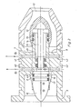
- Fig. 1 in abgebrochener Darstellung eine Zielbohrstange mit darin angeordnetem Drosselventil (Hebelbetätigung),
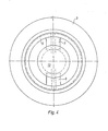
- Fig. 2 Querschnitt des Drosselventils (druckmittelbetätigt),
- Fig. 3 in abgebrochener Darstellung Querschnitt durch eine Zielbohrstange mit darin angeordnetem Drosselventil, Draufsicht des Widerstandskörpers (druckmittelbetätigt),
- Fig. 4 anströmseitige Ansicht des Innenrohres mit darin angeordnetem Drosselventil.
- 1 is a broken view of a target boring bar with throttle valve arranged therein (lever actuation),
- 2 cross section of the throttle valve (actuated by pressure medium),
- 3 shows a broken cross-section through a target boring bar with a throttle valve arranged therein, top view of the resistance body (actuated by pressure medium),
- Fig. 4 upstream view of the inner tube with a throttle valve arranged therein.
In der Zeichnung Figur 1 ist in abgebrochener Darstellung eine Zielbohrstange allgemein mit dem Bezugszeichen 1 versehen. Sie besteht aus einem im Bohrloch feststehenden Außenrohr 2, welches auf seiner Außenseite mit schwenkbar an diesem gelagerten, nicht dargestellten Steuerleisten versehen ist, die sich auf den Stößen des Bohrloches abstützen und über hydraulisch beaufschlagbare Zylinder einzeln verstellt werden können, um die Richtung des Bohrgestänges zu korrigieren. Drehbar im Außenrohr 2 ist ein Innenrohr 3 gelagert. Drehfest mit dem Innenrohr 3 verbunden ist konzentrisch in diesem ein allgemein mit 4 bezeichnetes Drosselventil angeordnet. Das Drosselventil 4 besteht aus einem ringförmigen Grundkörper 5, in dem konzentrisch ein Hohlkörper 6 angebracht ist, der über Stege 7 und 8 mit dem Grundkörper 5 verbunden ist. Die Stege 7 und 8 sind innen hohl ausgebildet und fluchten mit Öffnungen 9 und 10 im Innenrohr 3. Die Öffnungen 9 und 10 münden in Kammern 11, die ringförmig um das Innenrohr 3 im Außenrohr 2 herumgeführt sind. Der Grundkörper 5 ist beidseitig offen, wobei eine Seite 12 verjüngt ausgebildet ist. Auch der Hohlkörper 6 ist beidseitig offen. Auf dem Außenumfang des Hohlkörpers 6 und zwar an seinem der verjüngten Seite 12 des Grundkörpers 5 zugewandten Ende ist eine stromlinienförmige Kappe 13 verschiebbar gelagert und mit Ringdichtungen 14 und 15 gegen den Hohlkörper abgedichtet. An seinem anderen Ende verfügt der Hohlkörper 6 über eine weitere Kappe 16, die jedoch in dem durch das Hohlkörperende gebildeten Zylinder als Kolben geführt und mit Ringdichtungen 17 und 18 gegen den Hohlkörper 6 abgedichtet ist. Die Kappen 13 und 16 sind mit einer Stange 19 verbunden. Dort, wo die Stange 19 den Stegbereich passiert, greifen die abtriebsseitigen Enden 20 und 21 von als Gabelwippen 22 und 23 ausgebildeten Hebeln an der Stange 19 an. Die Gabelwippen 22 und 23 sind am Grundkörper 5 drehbar gelagert. Die antriebbseitigen Enden 24 und 25 der Gabelwippen 22 und 23 sind an Zapfen 26 befestigt. Die Zapfen 26 sind an einem Ring 27 angeordnet, der um das Innenrohr 3 herumgeführt ist und drehbar an Rotationslagern 28 gelagert, die an einem Ringkolben 29 befestigt sind. Der Ringkolben 29 ist lediglich in axialer Richtung verschiebbar. Der Ringkolben 29 wird z.B. über Druckmittelkanäle 30 und 31 mit Druckmittel beaufschlagt. Mit Hilfe der Dichtungen 32, 33 und 34 sind der Ringkolben und die Druckmittelkanäle gegen das Außenrohr 2 abgedichet. Wird der Ringkolben 29 im Ringraum 11 in eine Richtung verschoben, so verschieben die Gabelwippen 22 und 23 die Stange 19 in die entgegengesetzte Richtung. Die Stange 19, an der die Kappen 13 und 16 angeordnet sind, verschiebt somit die Kappen 13 und 16 entweder in Richtung auf die verjüngte Öffnung 12 des Grundkörpers 5, wobei im Extremfall die Kappe 13 auf den Rand der Öffnung 12 aufliegt. Die Öffnung 12 mündet im Spülflüssigkeitskanal 35, der Spülflüssigkeit vom nicht dargestellten Bohrlochmund zur ebenfalls nicht dargestellten Bohrkrone führt. Die Spülflüssigkeit strömt auf die Kappe 13 zu, an dieser, dem Hohlkörper 6 und der Kappe 16 vorbei, zur Bohrkrone. Nicht dargestellte Meßinstrumente im Außenrohr 2, die Meßwerte über den Zustand der Zielbohrstange und deren Richtung aufnehmen, geben diese an einen ebenfalls nicht dargestellten Wandler im Außenrohr 2 weiter, der die elektrischen Impulse in hydraulische Impulse umwandelt, die über die Kanäle 30 und 31 den Ringkolben 29 betätigen. Die Betätigung des Ringkolbens 29 führt zur Verschiebung der Kappen 13 und 16 und somit zu Querschnittsveränderungen des Spülflüssigkeitsquerschnitts. Hierdurch werden Druckpulse auf den Spülflüssigkeitsstrom übertragen, die durch geeignete Instrumente am Bohrlochmund aufgefangen und weiterverarbeitet werden. Zum Einbau der Gabelwippen und für Wartungsarbeiten ist der Ringraum 11 über Deckel 36 zugänglich.In the drawing in FIG. 1, a target boring bar is generally provided with the reference number 1 in a broken-off representation. It consists of an
In den Figuren 2 und 3 ist eine weitere Ausführungsform der erfindungsgemäßen Vorrichtung dargestellt, wobei gleiche Teile wie in Figur 1 mit denselben Bezugszeichen versehen sind. Im Unterschied zum Drosselventil gemäß Figur 1 werden die Kappen 13 und 16 hydraulisch bzw. pneumatisch betätigt. Ein Ringkolben entfältt daher, ebensowie die Gabelwippen. Dafür sind in den Stegen Kanäle 40 und 41 sowie 42 und 43 vorgesehen, die mit Kanälen 44 bis 47 im Innenrohr 3 fluchten. Die Kanäle 40 bis 47 werden von einer nicht dargestellten Druckmittelversorgung im Außenrohr 2 beaufschlagt. Die Kanäle 40 bis 43 münden in zwei voneinander getrennten Kammern 48 und 49 im Hohlkörper 6. Das Druckmittelströmt je nach gewünschter Verschieberichtung der Kappen 13 und 16 in die Kammern 48 oder 49 und drückt somit entweder die Kappe 13 zur Öffnung 12 oder die Kappe 16 zur entgegengesetzten Öffnung des Grundkörpers 5, wodurch sich die oben angesprochene Druckpulserzeugung im Flüssigkeitsstrom ergibt. Durch entsprechende Gestaltung der Durchmesserverhältnisse von d1, d2 und d3 ergibt sich die Möglichkeit der hydrostatischen Druckkompensation.
Ist w1 = w2 = w3 = 0 so ist, abgesehen von der axialen Systemausdehnung (statisches Druckgefälle)
p1 = p2 = p3
und über
d1² - d2² ![]()
ist durch die äußere Strömung (w = 0)
v1 = v2 = 0.FIGS. 2 and 3 show a further embodiment of the device according to the invention, the same parts as in FIG. 1 being provided with the same reference numerals. In contrast to the throttle valve according to FIG. 1, the
If w1 = w2 = w3 = 0 then, apart from the axial system expansion (static pressure drop)
p1 = p2 = p3
and over
d1² - d2² ![]()
is due to the external flow (w = 0)
v1 = v2 = 0.
Das heißt: Der Strömungswiderstandskörper (Kappen 13 und 16 und Hohlkörper 6) ist hydrostatisch druckkompensiert und erfährt keine Axialverschiebung durch die äußeren Druckkräfte.This means that the flow resistance body (caps 13 and 16 and hollow body 6) is hydrostatically pressure-compensated and does not experience any axial displacement due to the external pressure forces.
Ist w1 ≠ w2 ≠ w3 dann ist über die Energiegleichung von Bernulli
p1 ≠ p2 ≠ p3.If w1 ≠ w2 ≠ w3 then it is about Bernulli's energy equation
p1 ≠ p2 ≠ p3.
D.h.: Das System areitet über
w3 < w2 < w1 und d1² - d2² ![]()
unter Berücksichtigung der Strömungsverluste aus Form, Oberfläche und Strömungszustandsänderung hydrodynamisch teildruckkompensiert und teilweise kraftkompensiert (axial).Ie: The system is over
w3 <w2 <w1 and d1² - d2² ![]()
taking into account the flow losses from shape, surface and flow state change hydrodynamically partial pressure compensated and partly force compensated (axial).
Claims (10)
Priority Applications (1)
| Application Number | Priority Date | Filing Date | Title |
|---|---|---|---|
| AT86111862T ATE48179T1 (en) | 1985-08-31 | 1986-08-27 | DEVICE, PARTICULARLY FOR USE UNDERGROUND, FOR REMOTE TRANSMISSION OF INFORMATION FROM A BOREHOLE. |
Applications Claiming Priority (2)
| Application Number | Priority Date | Filing Date | Title |
|---|---|---|---|
| DE19853531226 DE3531226A1 (en) | 1985-08-31 | 1985-08-31 | DEVICE, IN PARTICULAR FOR UNDERGROUND APPLICATION FOR REMOTE TRANSMISSION OF INFORMATION FROM A DRILL HOLE |
| DE3531226 | 1985-08-31 |
Publications (3)
| Publication Number | Publication Date |
|---|---|
| EP0214554A2 true EP0214554A2 (en) | 1987-03-18 |
| EP0214554A3 EP0214554A3 (en) | 1987-07-29 |
| EP0214554B1 EP0214554B1 (en) | 1989-11-23 |
Family
ID=6279890
Family Applications (1)
| Application Number | Title | Priority Date | Filing Date |
|---|---|---|---|
| EP86111862A Expired EP0214554B1 (en) | 1985-08-31 | 1986-08-27 | Down-hole device for transmitting information from a well |
Country Status (10)
| Country | Link |
|---|---|
| US (1) | US4784229A (en) |
| EP (1) | EP0214554B1 (en) |
| JP (1) | JPS62117984A (en) |
| AT (1) | ATE48179T1 (en) |
| AU (3) | AU6212286A (en) |
| BR (1) | BR8604152A (en) |
| CA (1) | CA1261816A (en) |
| DE (2) | DE3531226A1 (en) |
| SU (1) | SU1642958A3 (en) |
| ZA (1) | ZA866610B (en) |
Cited By (2)
| Publication number | Priority date | Publication date | Assignee | Title |
|---|---|---|---|---|
| AU651764B2 (en) * | 1985-08-31 | 1994-07-28 | Bergwerksverband Gmbh | Apparatus, particularly for use under ground, for teletransmission of information from a borehole |
| CN105573248A (en) * | 2016-01-13 | 2016-05-11 | 南京航空航天大学 | Flexible member assembling dimensional deviation control method based on multi-station assembly jig compensation |
Families Citing this family (2)
| Publication number | Priority date | Publication date | Assignee | Title |
|---|---|---|---|---|
| US5957221A (en) | 1996-02-28 | 1999-09-28 | Baker Hughes Incorporated | Downhole core sampling and testing apparatus |
| DE19607402C1 (en) * | 1996-02-28 | 1997-07-10 | Welldone Engineering Gmbh | Device for transmitting information within a drill pipe string of a drilling device by means of pressure pulses in a flowing liquid, in particular drilling fluid |
Citations (6)
| Publication number | Priority date | Publication date | Assignee | Title |
|---|---|---|---|---|
| DE2941102A1 (en) * | 1979-10-08 | 1981-04-16 | Dresser Industries, Inc., 75221 Dallas, Tex. | Measuring and transmitting apparatus used in drill string - is self-contained and forms output signals modulated into mud flow |
| DE2161353C2 (en) * | 1970-12-10 | 1982-07-08 | Société Nationale Elf Aquitaine (Production) S.A., 92400 Courbevoie | Device for the transmission of measured values from a borehole by means of the drilling fluid |
| DE3028813C2 (en) * | 1980-07-30 | 1983-09-08 | Christensen, Inc., 84115 Salt Lake City, Utah | Method and device for the remote transmission of information |
| DE3000239C2 (en) * | 1980-01-05 | 1983-10-20 | Bergwerksverband Gmbh, 4300 Essen | Facility for producing targeted holes |
| DE3233982C1 (en) * | 1982-09-14 | 1983-10-27 | Christensen, Inc., 84115 Salt Lake City, Utah | Auxiliary controlled valve located in a drill string |
| EP0134467A2 (en) * | 1983-07-19 | 1985-03-20 | Bergwerksverband GmbH | Target-directed drilling rod for rotating boring tools with flushing duct for underground mining |
Family Cites Families (6)
| Publication number | Priority date | Publication date | Assignee | Title |
|---|---|---|---|---|
| US3255353A (en) * | 1962-12-21 | 1966-06-07 | Serge A Scherbatskoy | Apparatus for nuclear well logging while drilling |
| US4044834A (en) * | 1975-04-09 | 1977-08-30 | Perkins Lee E | Apparatus and method for controlling the flow of fluids from a well bore |
| DE3046122C2 (en) * | 1980-12-06 | 1984-05-17 | Bergwerksverband Gmbh, 4300 Essen | Equipment for making targeted bores with a target boring bar |
| US4470430A (en) * | 1981-05-26 | 1984-09-11 | Lancaster Robert D | Drilling choke |
| NL8302429A (en) * | 1982-07-10 | 1984-02-01 | Sperry Sun Inc | DEVICE FOR PROCESSING SIGNALS IN A DRILLING HOLE DURING DRILLING. |
| DE3531226A1 (en) * | 1985-08-31 | 1987-03-19 | Schwing Hydraulik Elektronik | DEVICE, IN PARTICULAR FOR UNDERGROUND APPLICATION FOR REMOTE TRANSMISSION OF INFORMATION FROM A DRILL HOLE |
-
1985
- 1985-08-31 DE DE19853531226 patent/DE3531226A1/en active Granted
-
1986
- 1986-08-27 AT AT86111862T patent/ATE48179T1/en active
- 1986-08-27 DE DE8686111862T patent/DE3667093D1/en not_active Expired
- 1986-08-27 EP EP86111862A patent/EP0214554B1/en not_active Expired
- 1986-08-28 SU SU864028087A patent/SU1642958A3/en active
- 1986-08-29 CA CA000517249A patent/CA1261816A/en not_active Expired
- 1986-08-29 BR BR8604152A patent/BR8604152A/en not_active IP Right Cessation
- 1986-09-01 AU AU62122/86A patent/AU6212286A/en not_active Abandoned
- 1986-09-01 JP JP61203918A patent/JPS62117984A/en active Pending
- 1986-09-01 ZA ZA866610A patent/ZA866610B/en unknown
-
1987
- 1987-12-10 US US07/132,613 patent/US4784229A/en not_active Expired - Fee Related
-
1990
- 1990-07-17 AU AU59125/90A patent/AU5912590A/en not_active Abandoned
-
1993
- 1993-06-11 AU AU41233/93A patent/AU651764B2/en not_active Expired - Fee Related
Patent Citations (6)
| Publication number | Priority date | Publication date | Assignee | Title |
|---|---|---|---|---|
| DE2161353C2 (en) * | 1970-12-10 | 1982-07-08 | Société Nationale Elf Aquitaine (Production) S.A., 92400 Courbevoie | Device for the transmission of measured values from a borehole by means of the drilling fluid |
| DE2941102A1 (en) * | 1979-10-08 | 1981-04-16 | Dresser Industries, Inc., 75221 Dallas, Tex. | Measuring and transmitting apparatus used in drill string - is self-contained and forms output signals modulated into mud flow |
| DE3000239C2 (en) * | 1980-01-05 | 1983-10-20 | Bergwerksverband Gmbh, 4300 Essen | Facility for producing targeted holes |
| DE3028813C2 (en) * | 1980-07-30 | 1983-09-08 | Christensen, Inc., 84115 Salt Lake City, Utah | Method and device for the remote transmission of information |
| DE3233982C1 (en) * | 1982-09-14 | 1983-10-27 | Christensen, Inc., 84115 Salt Lake City, Utah | Auxiliary controlled valve located in a drill string |
| EP0134467A2 (en) * | 1983-07-19 | 1985-03-20 | Bergwerksverband GmbH | Target-directed drilling rod for rotating boring tools with flushing duct for underground mining |
Cited By (3)
| Publication number | Priority date | Publication date | Assignee | Title |
|---|---|---|---|---|
| AU651764B2 (en) * | 1985-08-31 | 1994-07-28 | Bergwerksverband Gmbh | Apparatus, particularly for use under ground, for teletransmission of information from a borehole |
| CN105573248A (en) * | 2016-01-13 | 2016-05-11 | 南京航空航天大学 | Flexible member assembling dimensional deviation control method based on multi-station assembly jig compensation |
| CN105573248B (en) * | 2016-01-13 | 2018-01-30 | 南京航空航天大学 | Sheet metal assembly dimensional discrepancy control method based on the compensation of multistation assembling jig |
Also Published As
| Publication number | Publication date |
|---|---|
| DE3531226C2 (en) | 1987-09-24 |
| DE3667093D1 (en) | 1989-12-28 |
| DE3531226A1 (en) | 1987-03-19 |
| CA1261816A (en) | 1989-09-26 |
| EP0214554B1 (en) | 1989-11-23 |
| EP0214554A3 (en) | 1987-07-29 |
| US4784229A (en) | 1988-11-15 |
| AU651764B2 (en) | 1994-07-28 |
| AU5912590A (en) | 1990-11-01 |
| JPS62117984A (en) | 1987-05-29 |
| ATE48179T1 (en) | 1989-12-15 |
| SU1642958A3 (en) | 1991-04-15 |
| AU6212286A (en) | 1987-03-05 |
| ZA866610B (en) | 1987-05-27 |
| AU4123393A (en) | 1993-08-19 |
| BR8604152A (en) | 1987-04-28 |
Similar Documents
| Publication | Publication Date | Title |
|---|---|---|
| EP0134467B1 (en) | Target-directed drilling rod for rotating boring tools with flushing duct for underground mining | |
| DE4126249C2 (en) | Telemetry device in particular for the transmission of measurement data during drilling | |
| DE2309605C2 (en) | Electroacoustic transducer device, especially for use in flow measurement systems | |
| DE2233324C3 (en) | Device for borehole measurement during drilling | |
| DE3032299C2 (en) | ||
| DE60305733T2 (en) | DRILLING A DRILL | |
| DE112008003203B4 (en) | Pressure compensation and rotary seal system for a tool during drilling | |
| DE3511916A1 (en) | ROTARY ACTUATOR VALVE FOR DRILLING LIQUID REMOTE TRANSMISSION SYSTEMS | |
| EP0317605A1 (en) | Device for guiding a drilling tool and/or pipe string | |
| DE10106080C2 (en) | Deep hole well logger having means for transmitting logging data | |
| DE3733913A1 (en) | DEVICE AND METHOD FOR PRODUCING OVERPRESSURE IMPULSES IN A DRILLING MUD FLOW | |
| DE3028813C2 (en) | Method and device for the remote transmission of information | |
| DE3208469A1 (en) | DEVICE FOR ANCHORING AN INSTRUMENT IN A CAVITY, EQUIPPED WITH FOLDABLE ARMS | |
| DE2919007C2 (en) | Core drilling equipment for rock boreholes | |
| EP0131771A1 (en) | Drilling device, especially for underground mining | |
| DE3032834C2 (en) | ||
| DE3242905A1 (en) | DEVICE FOR MEASURING PRESSURE IN A HOLE | |
| DE3113749A1 (en) | DEVICE FOR REMOTELY TRANSMITTING INFORMATION FROM A DRILL HOLE TO THE GROUND SURFACE DURING THE OPERATION OF A DRILLING DEVICE | |
| DE2161353A1 (en) | Hydraulically operated device for the transmission of shaft bottom measurement signals to the surface station | |
| DE3000239C2 (en) | Facility for producing targeted holes | |
| EP0214554A2 (en) | Down-hole device for transmitting information from a well | |
| EP0486751B1 (en) | Directional drill string with an integrated electrical generator | |
| DE3132807A1 (en) | DEVICE FOR SIGNALING WITHIN A DRILL HOLE DURING THE DRILLING PROCESS | |
| DE19621849A1 (en) | Borehole drilling device for rotating and for moving tube lengths axially | |
| CH653406A5 (en) | DEVICE FOR PRODUCING TARGETED HOLES. |
Legal Events
| Date | Code | Title | Description |
|---|---|---|---|
| PUAI | Public reference made under article 153(3) epc to a published international application that has entered the european phase |
Free format text: ORIGINAL CODE: 0009012 |
|
| AK | Designated contracting states |
Kind code of ref document: A2 Designated state(s): AT BE CH DE FR GB LI SE |
|
| PUAL | Search report despatched |
Free format text: ORIGINAL CODE: 0009013 |
|
| 17P | Request for examination filed |
Effective date: 19870422 |
|
| AK | Designated contracting states |
Kind code of ref document: A3 Designated state(s): AT BE CH DE FR GB LI SE |
|
| 17Q | First examination report despatched |
Effective date: 19880520 |
|
| GRAA | (expected) grant |
Free format text: ORIGINAL CODE: 0009210 |
|
| AK | Designated contracting states |
Kind code of ref document: B1 Designated state(s): AT BE CH DE FR GB LI SE |
|
| REF | Corresponds to: |
Ref document number: 48179 Country of ref document: AT Date of ref document: 19891215 Kind code of ref document: T |
|
| ET | Fr: translation filed | ||
| REF | Corresponds to: |
Ref document number: 3667093 Country of ref document: DE Date of ref document: 19891228 |
|
| GBT | Gb: translation of ep patent filed (gb section 77(6)(a)/1977) | ||
| PLBE | No opposition filed within time limit |
Free format text: ORIGINAL CODE: 0009261 |
|
| STAA | Information on the status of an ep patent application or granted ep patent |
Free format text: STATUS: NO OPPOSITION FILED WITHIN TIME LIMIT |
|
| 26N | No opposition filed | ||
| PGFP | Annual fee paid to national office [announced via postgrant information from national office to epo] |
Ref country code: GB Payment date: 19930805 Year of fee payment: 8 |
|
| PGFP | Annual fee paid to national office [announced via postgrant information from national office to epo] |
Ref country code: FR Payment date: 19930816 Year of fee payment: 8 |
|
| PGFP | Annual fee paid to national office [announced via postgrant information from national office to epo] |
Ref country code: SE Payment date: 19930825 Year of fee payment: 8 Ref country code: AT Payment date: 19930825 Year of fee payment: 8 |
|
| PGFP | Annual fee paid to national office [announced via postgrant information from national office to epo] |
Ref country code: BE Payment date: 19930906 Year of fee payment: 8 |
|
| PGFP | Annual fee paid to national office [announced via postgrant information from national office to epo] |
Ref country code: CH Payment date: 19930920 Year of fee payment: 8 |
|
| PGFP | Annual fee paid to national office [announced via postgrant information from national office to epo] |
Ref country code: DE Payment date: 19931029 Year of fee payment: 8 |
|
| PG25 | Lapsed in a contracting state [announced via postgrant information from national office to epo] |
Ref country code: GB Effective date: 19940827 Ref country code: AT Effective date: 19940827 |
|
| PG25 | Lapsed in a contracting state [announced via postgrant information from national office to epo] |
Ref country code: SE Effective date: 19940828 |
|
| PG25 | Lapsed in a contracting state [announced via postgrant information from national office to epo] |
Ref country code: LI Effective date: 19940831 Ref country code: CH Effective date: 19940831 Ref country code: BE Effective date: 19940831 |
|
| EAL | Se: european patent in force in sweden |
Ref document number: 86111862.8 |
|
| BERE | Be: lapsed |
Owner name: BERGWERKSVERBAND G.M.B.H. Effective date: 19940831 Owner name: SCHWING HYDRAULIK ELEKTRONIK G.B.M.H & CO. Effective date: 19940831 |
|
| GBPC | Gb: european patent ceased through non-payment of renewal fee |
Effective date: 19940827 |
|
| PG25 | Lapsed in a contracting state [announced via postgrant information from national office to epo] |
Ref country code: FR Effective date: 19950428 |
|
| REG | Reference to a national code |
Ref country code: CH Ref legal event code: PL |
|
| PG25 | Lapsed in a contracting state [announced via postgrant information from national office to epo] |
Ref country code: DE Effective date: 19950503 |
|
| EUG | Se: european patent has lapsed |
Ref document number: 86111862.8 |
|
| REG | Reference to a national code |
Ref country code: FR Ref legal event code: ST |