EP0214389A2 - Cooling system for automotive engine or the like - Google Patents
Cooling system for automotive engine or the like Download PDFInfo
- Publication number
- EP0214389A2 EP0214389A2 EP86108740A EP86108740A EP0214389A2 EP 0214389 A2 EP0214389 A2 EP 0214389A2 EP 86108740 A EP86108740 A EP 86108740A EP 86108740 A EP86108740 A EP 86108740A EP 0214389 A2 EP0214389 A2 EP 0214389A2
- Authority
- EP
- European Patent Office
- Prior art keywords
- coolant
- radiator
- reservoir
- coolant jacket
- temperature sensor
- Prior art date
- Legal status (The legal status is an assumption and is not a legal conclusion. Google has not performed a legal analysis and makes no representation as to the accuracy of the status listed.)
- Granted
Links
Images


Classifications
-
- F—MECHANICAL ENGINEERING; LIGHTING; HEATING; WEAPONS; BLASTING
- F01—MACHINES OR ENGINES IN GENERAL; ENGINE PLANTS IN GENERAL; STEAM ENGINES
- F01P—COOLING OF MACHINES OR ENGINES IN GENERAL; COOLING OF INTERNAL-COMBUSTION ENGINES
- F01P11/00—Component parts, details, or accessories not provided for in, or of interest apart from, groups F01P1/00 - F01P9/00
- F01P11/14—Indicating devices; Other safety devices
- F01P11/18—Indicating devices; Other safety devices concerning coolant pressure, coolant flow, or liquid-coolant level
-
- F—MECHANICAL ENGINEERING; LIGHTING; HEATING; WEAPONS; BLASTING
- F01—MACHINES OR ENGINES IN GENERAL; ENGINE PLANTS IN GENERAL; STEAM ENGINES
- F01P—COOLING OF MACHINES OR ENGINES IN GENERAL; COOLING OF INTERNAL-COMBUSTION ENGINES
- F01P3/00—Liquid cooling
- F01P3/22—Liquid cooling characterised by evaporation and condensation of coolant in closed cycles; characterised by the coolant reaching higher temperatures than normal atmospheric boiling-point
- F01P3/2271—Closed cycles with separator and liquid return
Definitions
- the present invention relates generally to an evaporative type cooling system for an internal combustion engine wherein liquid coolant is permitted to boil and the vapor used as a vehicle for removing heat therefrom, and more specifically to such a system which does not require a plurality of electromagnetic valves and a complex control circuit for its operation and which can constantly maintain the cooling circuit of the system free of contaminating air and the like non-condensble matter.
- the warm-up characteristics of the engine are undesirably sluggish.
- the temperature difference between the inlet and discharge ports of the coolant jacket is 4 degrees
- the amount of heat which 1 Kg of water may effectively remove from the engine under such conditions is 4 Kcal.
- the cooling system is required to remove approximately 4000 Kcal/h.
- a flow rate of 167 liter/min (viz., 4000 - 60 x 14) must be produced by the water pump. This of course undesirably consumes several horsepower.
- Fig. 2 shows an arrangement disclosed in Japanese Patent Application Second Provisional Publication Sho. 57-57608. This arrangement has attempted to vaporize a liquid coolant and use the gaseous form thereof as a vehicle for removing heat from the engine.
- the radiator 1 and the coolant jacket 2 are in constant and free communication via conduits 3, 4 whereby the coolant which condenses in the radiator 1 is returned to the coolant jacket 2 little by little under the influence of gravity.
- this filter permits gaseous coolant to readily escape from the system, inducing the need for frequent topping up of the coolant level.
- a further problem with this arrangement has come in that some of the air, which is sucked into the cooling system as the engine cools, tends to dissolve in the water, whereby upon start up of the engine, the dissolved air tends to come out of solution and forms small bubbles in the radiator which adhere to the walls thereof and form an insulating layer. The undissolved air also tends to collect in the upper section of the radiator and inhibit the convection-like circulation of the vapor from the cylinder block to the radiator. This of course further deteriorates the performance of the device.
- European Patent Application Provisional Publication No. 0 059 423 published on September 8, 1982 discloses another arrangement wherein, liquid coolant in the coolant jacket of the engine, is not forcefully circulated therein and permitted to absorb heat to the point of boiling.
- the gaseous coolant thus generated is adiabatically compressed in a compressor so as to raise the temperature and pressure thereof and thereafter introduced into a heat exchanger (radiator). After condensing, the coolant is temporarily stored in a reservoir and recycled back into the coolant jacket via a flow control valve.
- This arrangement has suffered from the drawback that when the engine is stopped and cools down the coolant vapor condenses and induces sub-atmospheric conditions which tend to induce air to leak into the system. This air tends to be forced by the compressor along with the gaseous coolant into the radiator.
- the temperature of the radiator is controlled by selective energizations of the fan 9 which maintains a rate of condensation therein sufficient to provide a liquid seal at the bottom of the device.
- Condensate discharged from the radiator via the above mentioned liquid seal is collected in a small reservoir-like arrangement 10 and pumped back up to the separation tank via a small constantly energized pump 11.
- the rate of condensation in the consensor is controlled by a temperature sensor disposed on or in the condensor per se.
- This arrangement while providing an arrangement via which air can be initially purged to some degree from the system tends to, due to the nature of the arrangement which permits said initial non-condensible matter to be forced out of the system, suffers from rapid loss of coolant when operated at relatively high altitudes. Further, once the engine cools air is relatively freely admitted back into the system. The provision of the bulky separation tank 6 also renders engine layout difficult.
- Japanese Patent Application First Provisional Publication No. sho. 56-32026 discloses an arrangement wherein the structure defining the cylinder head and cylinder liners are covered in a porous layer of ceramic material 12 and wherein coolant is sprayed into the cylinder block from shower-like arrangements 13 located above the cylinder heads 14.
- the interior of the coolant jacket defined within the engine proper is essentially filled with gaseous coolant during engine operation at which time liquid coolant sprayed onto the ceramic layers 12.
- this arrangement has proven totally unsatisfactory in that upon boiling of the liquid coolant absorbed into the ceramic layers, the vapor thus produced and which escapes toward and into the coolant jacket, inhibits the penetration of fresh liquid coolant into the layers and induces the situation wherein rapid overheat and thermal damage of the ceramic layers 12 and/or engine soon results. Further, this arrangement is of the closed circuit type and is plagued with air co ntamination and blockages in the radiator similar to the compressor equipped arrangement discussed above.
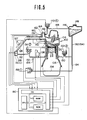
- Fig. 7 shows an arrangement which is disclosed in United States Patent No. 4,549,505 issued on October 29, 1985 in the name of Hirano. The disclosure of this application is hereby incorporated by reference thereto. For convenience the same numerals as used in the above mentioned Patent are also used in Fig. 7.
- a reservoir in which coolant is stored is arranged to constantly communicate with a lower portion of a cooling circuit which includes the coolant jacket and the radiator in which the coolant vapor is condensed.
- a small coolant pump returns condensate from the radiator to the coolant jacket in response to a temperature sensor disposed in the coolant jacket.
- a cooling fan or like device is operated in response to a second temperature sensor disposed at the bottom of the radiator.
- the reservoir communicates with the ambient atmosphere via a valve which opens upon the pressure differential between the interior of the reservoir and the ambient atmosphere reaching predetermined positive and negative magnitudes.
- the present invention takes the form of a cooling system for an automotive engine or the like which has a structure subject to a high heat flux, the system being characterized by: a coolant jacket disposed about the structure and into which coolant is introduced in liquid form and discharged in gaseous form; a radiator in fluid commuication with the coolant jacket and in which coolant vapor is condensed to form a condensate, the radiator including a small collection vessel disposed at the bottom of the radiator in which the condensate is collected; a first temperature sensor disposed in the coolant jacket; a pump which pumps the condensate from the radiator to the coolant jacket through a coolant return conduit, the pump being responsive to the first temperature sensor in a manner that the pump is energized when the temperature of the coolant in the coolant jacket is above a first predetermined level; a second temperature sensor disposed in the radiator; a device associated with the radiator for varying the rate of heat exchange between the radiator and a cooling medium surrounding the radiator, the device being responsive to
- FIG. 6 of the drawings shows an engine system to which a first embodiment of the invention is applied.
- an internal combustion engine 200 includes a cylinder block 204 on which a cylinder had 206 is detachably secured.
- the cylinder head and block are formed with suitably cavities which define a coolant jacket 208 about structure of the engine subject to high heat flux (e.g. combustion chambers exhaust valves conduits etc.,).
- a selectively energizable electrically driven fan 218 Located adjacent the radiator 216 is a selectively energizable electrically driven fan 218 which is arranged to induce a cooling draft of air to pass over the heat exchanging surface of the radiator 216 upon being put into operation.
- a coolant return conduit 222 Leading from the lower tank 220 to a coolant inlet port 221 formed in the cylinder head 206 is a coolant return conduit 222.
- a small capacity electrically driven pump 224 is disposed in this conduit at a location relatively close to the radiator 216.
- the capacity of this pump 224 is selected to be such that it pumps coolant a rate slightly greater than the maximum requirement of the engine 200. This rate can be approximated using parameters such as the maximum amount of fuel combusted in the engine per unit time and confirmed by empirical results. It is important that the rate at which the pump 224 pumps be higher than the maximum requirement so that during engine operation the maintainance of the desired level of coolant in the coolant jacket will be assured under all modes of engine operation as will become apparent hereinlater.
- a coolant reservoir 226 is arranged to constantly communicate with the coolant return conduit 220 in a manner as shown. Viz., be disposed so that it is interposed in the coolant return conduit in a manner which divides the same into an upstream section (viz., the section which extends between the lower tank 220 and the reservoir 226) and a downstream section (the section which extends between the reservoir and the coolant jacket 208).
- the reservoir 226 is closed by a cap in which a relief valve 233 is disposed. This valve 233 is arranged to remain closed until the magnitude of the pressure differential between the interior of the reservoir 226 and the ambient atmosphere reaches a predetermined positive or negative value.
- the relief valve 233 is arranged to open when a positive pressure of 1.2Kg/cm2 is reached and when a negative presssure of 0.9Kg/cm2 develops in the reservoir.
- the vapor manifold 212 in this embodiment is formed with a riser portion 240.
- This riser portion 240 as shown, is provided with a cap 242 which hermetically closes the same.
- overflow conduit 246 Leading from one or more overflow ports 244 formed in the cylinder head 206 to the resrvoir 226 is an overflow conduit 246.
- the overflow port or ports 244 are arranged at a predetermined height "H" above the structure of the engine 200 which i s subject to maximum heat flux. Viz., the structure which defines the cylinder head, exhaust ports, valves etc. This height (H) is selected to ensure that the engine structure which is subject to high heat flux remains immersed in a depth of liquid coolant which ensures constant immersion even under heavy load operation when the boiling of the coolant becomes sufficiently vigourous to tend to induce localized dry-outs and cavitation. These phenomena are apt to cause localized overheating which can lead to serious engine damage.
- the overflow conduit 246 is arranged to extend into the reservoir 226 and terminate at a level above that at which the coolant return conduit 246 communicates with the same and distal from the location at which the upstream section of the coolant return conduit 222 communicates. With this arrangement any air or the like non-condensible matter which may be forced to bubble through the coolant in the reservoir 226 during operation of the engine tends not to enter the overflow conduit 246 and find its way back into the coolant jacket 208.
- a first temperature sensor 250 is disposed in the cylinder head at a level lower than "H" and thus in a manner to be immersed in the liquid coolant contained in the coolant jacket 208 proximate the highly heated engine structure.
- This sensor 250 is arranged to switch to a state wherein electrical current is supplied to the coolant return pump 224 upon a predetermined temperature being reached.
- the temperature is set at 85°C. This value is selected to correspond to the lowest temperature at which the coolant is apt to boil. For example, the temperature at which the coolant boils at elevated alititudes such as atop of a mountain.
- a second temperature sensor 252 is disposed in the lower tank 220. This sensor 252 is set to respond to the temperature of the coolant in the lower tank 220 reaching the same value as the first one, vi., 85°C.
- the above disclosed arrangement is such that when the engine 200 is subject to a cold start, viz., when the engine coolant is below 85°C by way of example, as the coolant in the coolant jacket 208 is not circulated at all the coolant therein quickly warms.
- the coolant return pump 224 Upon reaching the predetermined temperature the coolant return pump 224 is energized by temperature sensor 250 and coolant is pumped from the lower tank 220 to the coolant jacket 208 via conduit 222.
- the rate at which the coolant heats to its boiling point is high.
- the coolant vapor generated at this time produces pressure which displaces liquid coolant out of the cooling circuit (viz., a loop comprised of the coolant jacket 208, vapor manifold 212, vapor transfer conduit 214, radiator 216, and coolant return conduit 222.) into the reservoir 226.
- This increases the pressure in the cooling circuit and reservoir 226 until the pressure at which the relief valve 233 opens is reached.
- fan 218 is energized to increase the rate of heat exchange between the radiator 216 and the surrounding ambient air and thus strive to reduce the temperature in the lower tank 220.
- this energization is such as to maintain the interior of the system as essentially atmospheric and permit the level of liquid coolant in the radiator 216 to adjust itself in a manner which adjusts the surface area of the radi ator 216 available for the coolant vapor to release its latent heat of vaporization.
- the radiator 216 will tend to be partially filled with liquid coolant while in hotter environments the level will automatically lower in a manner to allow for the reduced difference in temperature between the interior and the exterior of the radiator 216.
- the temperature and pressure within the cooling circuit rises.
- the non-condensible matter eg. air
- the non-condensible matter which exhibits natural insulating properties and thus tends to be less heated (cooler) than the coolant vapor, tends to be pushed down toward the bottom of the radiator 216 and eventually discharged out of the cooling circuit into the reservoir 226.
- the relief valve 233 opens and vents the excess pressure.
- the maximum heat exchange capacity of the radiator 216 is selected to be greater than the maximum heat exchange requirement of system so that under normal circumstances the level of liquid coolant in the lower tank 220 should not fall below that at which return conduit 222 communicates therewith.
- the coolant used takes the form of water containing a suitably amount of anti-freeze and a trace of anti-corrosive. It will be noted that even through the coolant vapor which is transferred through the vapor conduit 214 to the radiator 216 contains very little anti-freeze, the latter tending to concentrate in the coolant jac ket, the constant energization of the coolant return pump 224 above a predetermined coolant temperature causes a small amount of coolant liquid coolant to be circulated through the overflow and coolant return conduits 246, 222 under nearly all modes of engine operation (including the cool-down mode following stoppage of the engine) and thus adequately prevents any notable concentration difference from occuring. Hence, in very cold climates freezing of the coolant in the radiator and like elements of system is essentially obviated.
- Fig. 9 shows a second embodiment of the present invention. This embodiment differs from the first one in that the overflow conduit is omitted and in that the reservoir 226' is formed on one side of the radiator 216'.
- the far 218 and pump 224 are controlled by a control circuit 300.
- This circuit is responsive to the outputs of the temperature sensors 250, 252.
Abstract
Description
- The present invention relates generally to an evaporative type cooling system for an internal combustion engine wherein liquid coolant is permitted to boil and the vapor used as a vehicle for removing heat therefrom, and more specifically to such a system which does not require a plurality of electromagnetic valves and a complex control circuit for its operation and which can constantly maintain the cooling circuit of the system free of contaminating air and the like non-condensble matter.
- In currently used "water cooled" internal combustion engines (liquid) is forcefully circulated by a water pump, through a cooling circuit including the engine coolant jacket and an air cooled radiator. This type of system encounters the drawback that a large volume of water is required to be circulated between the radiator and the coolant jacket in order to remove the required amount of heat.
- Further, due to the large mass of water inherently required, the warm-up characteristics of the engine are undesirably sluggish. For example, if the temperature difference between the inlet and discharge ports of the coolant jacket is 4 degrees, the amount of heat which 1 Kg of water may effectively remove from the engine under such conditions is 4 Kcal. Accordingly, in the case of an engine having an 1800cc displacement (by way of example) is operated full throttle, the cooling system is required to remove approximately 4000 Kcal/h. In order to achieve this, a flow rate of 167 liter/min (viz., 4000 - 60 x 14) must be produced by the water pump. This of course undesirably consumes several horsepower.
- Fig. 2 shows an arrangement disclosed in Japanese Patent Application Second Provisional Publication Sho. 57-57608. This arrangement has attempted to vaporize a liquid coolant and use the gaseous form thereof as a vehicle for removing heat from the engine. In this system the
radiator 1 and thecoolant jacket 2 are in constant and free communication viaconduits radiator 1 is returned to thecoolant jacket 2 little by little under the influence of gravity. - This arrangement while eliminating the power consuming coolant circulation pump which plagues the above mentioned arragement, has suffered from the drawbacks that the radiator, depending on its position with respect to the engine proper, tends to be at least partially filled with liquid coolant. This greatly reduces the surface area via which the gaseous coolant (for example steam) can effectively release its latent heat of vaporization and accordingly condense, and thus has lacked any notable improvement in cooling efficiency. Further, with this system in order to maintain the pressure within the coolant jacket and radiator at atmospheric level, a gas permeable
water shedding filter 5 is arranged as shown, to permit the entry of air into and out of the system. - However, this filter permits gaseous coolant to readily escape from the system, inducing the need for frequent topping up of the coolant level. A further problem with this arrangement has come in that some of the air, which is sucked into the cooling system as the engine cools, tends to dissolve in the water, whereby upon start up of the engine, the dissolved air tends to come out of solution and forms small bubbles in the radiator which adhere to the walls thereof and form an insulating layer. The undissolved air also tends to collect in the upper section of the radiator and inhibit the convection-like circulation of the vapor from the cylinder block to the radiator. This of course further deteriorates the performance of the device.
- European Patent Application Provisional Publication No. 0 059 423 published on September 8, 1982 discloses another arrangement wherein, liquid coolant in the coolant jacket of the engine, is not forcefully circulated therein and permitted to absorb heat to the point of boiling. The gaseous coolant thus generated is adiabatically compressed in a compressor so as to raise the temperature and pressure thereof and thereafter introduced into a heat exchanger (radiator). After condensing, the coolant is temporarily stored in a reservoir and recycled back into the coolant jacket via a flow control valve. This arrangement has suffered from the drawback that when the engine is stopped and cools down the coolant vapor condenses and induces sub-atmospheric conditions which tend to induce air to leak into the system. This air tends to be forced by the compressor along with the gaseous coolant into the radiator.
- Due to the difference in specific gravity, the above mentioned air tends to rise in the hot environment while the coolant which has condensed moves downwardly. The air, due to this inherent tendency to rise, tends to form pockets of air which cause a kind of "embolism" in the radiator and which badly impair the heat exchange ability thereof. With this arrangement the provision of the compressor renders the control of the pressure prevailing in the cooling circuit for the purpose of varying the coolant boiling point with load and/or engine speed difficult.
- United States Patent No. 4,367,699 issued on Jan. 11, 1983 in the name of Evans (see Fig. 3 of the drawings) discloses an engine system wherein the coolant is boiled and the vapor used to remove heat from the engine. This arrangement features a
separation tank 6 wherein gaseous and liquid coolant are initially separated. The liquid coolant is fed back to thecylinder block 7 under the influence of gravity while the relatively dry gaseous coolant (steam for example) is condensed in a fan cooledradiator 8. - The temperature of the radiator is controlled by selective energizations of the
fan 9 which maintains a rate of condensation therein sufficient to provide a liquid seal at the bottom of the device. Condensate discharged from the radiator via the above mentioned liquid seal is collected in a small reservoir-like arrangement 10 and pumped back up to the separation tank via a small constantly energized pump 11. The rate of condensation in the consensor is controlled by a temperature sensor disposed on or in the condensor per se. - This arrangement, while providing an arrangement via which air can be initially purged to some degree from the system tends to, due to the nature of the arrangement which permits said initial non-condensible matter to be forced out of the system, suffers from rapid loss of coolant when operated at relatively high altitudes. Further, once the engine cools air is relatively freely admitted back into the system. The provision of the
bulky separation tank 6 also renders engine layout difficult. - Japanese Patent Application First Provisional Publication No. sho. 56-32026 (see Fig. 4 of the drawings) discloses an arrangement wherein the structure defining the cylinder head and cylinder liners are covered in a porous layer of
ceramic material 12 and wherein coolant is sprayed into the cylinder block from shower-like arrangements 13 located above thecylinder heads 14. The interior of the coolant jacket defined within the engine proper is essentially filled with gaseous coolant during engine operation at which time liquid coolant sprayed onto theceramic layers 12. - However, this arrangement has proven totally unsatisfactory in that upon boiling of the liquid coolant absorbed into the ceramic layers, the vapor thus produced and which escapes toward and into the coolant jacket, inhibits the penetration of fresh liquid coolant into the layers and induces the situation wherein rapid overheat and thermal damage of the
ceramic layers 12 and/or engine soon results. Further, this arrangement is of the closed circuit type and is plagued with air co ntamination and blockages in the radiator similar to the compressor equipped arrangement discussed above. - Fig. 7 shows an arrangement which is disclosed in United States Patent No. 4,549,505 issued on October 29, 1985 in the name of Hirano. The disclosure of this application is hereby incorporated by reference thereto. For convenience the same numerals as used in the above mentioned Patent are also used in Fig. 7.
- This arrangement while solving the drawbacks encountered with the previously disclosed prior art has itself suffered from the drawbacks that it requires no less than four electromagnetic valves and a highly complex control circuit (in this case a micropressor) to control the same. This, while permitting the variation of the temperature at which the coolant boils with respect to the instant engine speed and load, increases the complextity and cost of the system considerably. Further, in the event that one of the valves or the control circuit malfunctions the operablity of the whole system is placed in jeopardy and is likely to result in engine damage or temporary inoperablity.
- It is an object of the present invention to provide an evaporative cooling system wherein without the need of complex control systems the cooling circuit of the system can be continually maintained essentially free of non-condensible matter.
- In brief, the above object is achieved by an arrangement wherein a reservoir in which coolant is stored is arranged to constantly communicate with a lower portion of a cooling circuit which includes the coolant jacket and the radiator in which the coolant vapor is condensed. A small coolant pump returns condensate from the radiator to the coolant jacket in response to a temperature sensor disposed in the coolant jacket. A cooling fan or like device is operated in response to a second temperature sensor disposed at the bottom of the radiator. The reservoir communicates with the ambient atmosphere via a valve which opens upon the pressure differential between the interior of the reservoir and the ambient atmosphere reaching predetermined positive and negative magnitudes.
- More specifically, the present invention takes the form of a cooling system for an automotive engine or the like which has a structure subject to a high heat flux, the system being characterized by: a coolant jacket disposed about the structure and into which coolant is introduced in liquid form and discharged in gaseous form; a radiator in fluid commuication with the coolant jacket and in which coolant vapor is condensed to form a condensate, the radiator including a small collection vessel disposed at the bottom of the radiator in which the condensate is collected; a first temperature sensor disposed in the coolant jacket; a pump which pumps the condensate from the radiator to the coolant jacket through a coolant return conduit, the pump being responsive to the first temperature sensor in a manner that the pump is energized when the temperature of the coolant in the coolant jacket is above a first predetermined level; a second temperature sensor disposed in the radiator; a device associated with the radiator for varying the rate of heat exchange between the radiator and a cooling medium surrounding the radiator, the device being responsive to the second temperature sensor in a manner to assume a condition in which the rate of heat exchange is increased upon the temperature in the radiator exceeding a predetermined level; a reservoir in which coolant is stored, the reservoir fluidly communicating with the return conduit; and a relief valve which controls fluid communication between the interior of the reservoir and the ambient atmosphere, the relief valve being arranged to remain closed until the pressure differential between the interior and the exterior of the reservoir reaches one of a predetermined positive value or a predetermined negative value.
- The features and advantages of the arrangement of the present invention will become more clearly appreciated from the following description taken in conjunction with the accompanying drawings in which:
- Figs. 1 to 4 show the prior art arrangements discussed in the opening paragraphs of the instant disclosure;
- Fig. 5 shows in schematic elevation the arrangement disclosed in the opening paragraphs of the instant disclosure in conjunction with United States Patent No. 4,549,505; and
- Figs. 6 and 7 show first and second embodiments of the present invention.
- Fig. 6 of the drawings shows an engine system to which a first embodiment of the invention is applied. In this arrangement an
internal combustion engine 200 includes acylinder block 204 on which a cylinder had 206 is detachably secured. The cylinder head and block are formed with suitably cavities which define acoolant jacket 208 about structure of the engine subject to high heat flux (e.g. combustion chambers exhaust valves conduits etc.,). Fluidly communicating with a vapor discharge port 210 formed in thecylinder head 206 via avapor manifold 212 andvapor conduit 214, is acondensor 216 or radiator as it will be referred to hereinafter. Located adjacent theradiator 216 is a selectively energizable electrically drivenfan 218 which is arranged to induce a cooling draft of air to pass over the heat exchanging surface of theradiator 216 upon being put into operation. - A
small collection reservoir 220 or lower tank as it will be referred to hereinlater, is provided at the bottom of theradiator 216 and arranged to collect the condensate produced therein. Leading from thelower tank 220 to a coolant inlet port 221 formed in thecylinder head 206 is acoolant return conduit 222. A small capacity electrically driven pump 224 is disposed in this conduit at a location relatively close to theradiator 216. The capacity of this pump 224 is selected to be such that it pumps coolant a rate slightly greater than the maximum requirement of theengine 200. This rate can be approximated using parameters such as the maximum amount of fuel combusted in the engine per unit time and confirmed by empirical results. It is important that the rate at which the pump 224 pumps be higher than the maximum requirement so that during engine operation the maintainance of the desired level of coolant in the coolant jacket will be assured under all modes of engine operation as will become apparent hereinlater. - A
coolant reservoir 226 is arranged to constantly communicate with thecoolant return conduit 220 in a manner as shown. Viz., be disposed so that it is interposed in the coolant return conduit in a manner which divides the same into an upstream section (viz., the section which extends between thelower tank 220 and the reservoir 226) and a downstream section (the section which extends between the reservoir and the coolant jacket 208). Thereservoir 226 is closed by a cap in which arelief valve 233 is disposed. Thisvalve 233 is arranged to remain closed until the magnitude of the pressure differential between the interior of thereservoir 226 and the ambient atmosphere reaches a predetermined positive or negative value. In the instant embodiment (by way of example) therelief valve 233 is arranged to open when a positive pressure of 1.2Kg/cm2 is reached and when a negative presssure of 0.9Kg/cm2 develops in the reservoir. - The
vapor manifold 212 in this embodiment is formed with ariser portion 240. Thisriser portion 240 as shown, is provided with acap 242 which hermetically closes the same. - Leading from one or
more overflow ports 244 formed in thecylinder head 206 to theresrvoir 226 is anoverflow conduit 246. With the present invention the overflow port orports 244 are arranged at a predetermined height "H" above the structure of theengine 200 which i s subject to maximum heat flux. Viz., the structure which defines the cylinder head, exhaust ports, valves etc. This height (H) is selected to ensure that the engine structure which is subject to high heat flux remains immersed in a depth of liquid coolant which ensures constant immersion even under heavy load operation when the boiling of the coolant becomes sufficiently vigourous to tend to induce localized dry-outs and cavitation. These phenomena are apt to cause localized overheating which can lead to serious engine damage. Theoverflow conduit 246 is arranged to extend into thereservoir 226 and terminate at a level above that at which thecoolant return conduit 246 communicates with the same and distal from the location at which the upstream section of thecoolant return conduit 222 communicates. With this arrangement any air or the like non-condensible matter which may be forced to bubble through the coolant in thereservoir 226 during operation of the engine tends not to enter theoverflow conduit 246 and find its way back into thecoolant jacket 208. - In order to control the operation of the coolant return pump 224 a
first temperature sensor 250 is disposed in the cylinder head at a level lower than "H" and thus in a manner to be immersed in the liquid coolant contained in thecoolant jacket 208 proximate the highly heated engine structure. Thissensor 250 is arranged to switch to a state wherein electrical current is supplied to the coolant return pump 224 upon a predetermined temperature being reached. In this embodiment the temperature is set at 85°C. This value is selected to correspond to the lowest temperature at which the coolant is apt to boil. For example, the temperature at which the coolant boils at elevated alititudes such as atop of a mountain. - In order to control the operation of the cooling
fan 218, asecond temperature sensor 252 is disposed in thelower tank 220. Thissensor 252 is set to respond to the temperature of the coolant in thelower tank 220 reaching the same value as the first one, vi., 85°C. - In operation the above disclosed arrangement is such that when the
engine 200 is subject to a cold start, viz., when the engine coolant is below 85°C by way of example, as the coolant in thecoolant jacket 208 is not circulated at all the coolant therein quickly warms. Upon reaching the predetermined temperature the coolant return pump 224 is energized bytemperature sensor 250 and coolant is pumped from thelower tank 220 to thecoolant jacket 208 viaconduit 222. However, as the volume of coolant circulated is not large by comparison with the arrangement shown in Fig. 1 of the drawings, the rate at which the coolant heats to its boiling point is high. The coolant vapor generated at this time produces pressure which displaces liquid coolant out of the cooling circuit (viz., a loop comprised of thecoolant jacket 208,vapor manifold 212,vapor transfer conduit 214,radiator 216, andcoolant return conduit 222.) into thereservoir 226. This of course increases the pressure in the cooling circuit andreservoir 226 until the pressure at which therelief valve 233 opens is reached. - If the natural draft of air over the heat exchanging surfaces of the
radiator 216 is such as to be insufficient to maintain the temperature of the coolant in the lower tank 220 (a mixture of the condensate which is formed via the condensation of the coolant vapor in theradiator 216 and the coolant which overflows from the coolant jacket via overflow conduit 246) below the predetermined level,fan 218 is energized to increase the rate of heat exchange between theradiator 216 and the surrounding ambient air and thus strive to reduce the temperature in thelower tank 220. - It will be noted that this energization is such as to maintain the interior of the system as essentially atmospheric and permit the level of liquid coolant in the
radiator 216 to adjust itself in a manner which adjusts the surface area of theradi ator 216 available for the coolant vapor to release its latent heat of vaporization. In cold climates theradiator 216 will tend to be partially filled with liquid coolant while in hotter environments the level will automatically lower in a manner to allow for the reduced difference in temperature between the interior and the exterior of theradiator 216. - In the event that some non-condensible matter finds its way into the cooling circuit to the degree that sufficient heat cannot be released from the system, the temperature and pressure within the cooling circuit rises. Simultaneously, the non-condensible matter (eg. air) which exhibits natural insulating properties and thus tends to be less heated (cooler) than the coolant vapor, tends to be pushed down toward the bottom of the
radiator 216 and eventually discharged out of the cooling circuit into thereservoir 226. Upon the pressure in the reservoir building to the above mentioned positive limit therelief valve 233 opens and vents the excess pressure. - This "hot purge" of non-condensible matter tends to maintain the system free of air and the like during running of the engine.
- It will be noted that the maximum heat exchange capacity of the
radiator 216 is selected to be greater than the maximum heat exchange requirement of system so that under normal circumstances the level of liquid coolant in thelower tank 220 should not fall below that at which returnconduit 222 communicates therewith. - When the
engine 200 is stopped it is advantageous to maintain the supply of electrical power to thefan 218, pump 224 andsensors engine 200 is stopped due to the heat which has accumulated in thecylinder head 206,cylinder block 204 and associated structure and prevents pressure build up which might displace coolant out of the cooling circuit to thereservoir 226 with sufficient violence that spillage or similar loss may occur. That is to say, if thefan 218 and pump, are permitted to continuation operation to remove heat from the system and circulate cooled coolant collected in thelower tank 220 until the temperatures in thecoolant jacket 208 andlower tank 220 drop to the above mentioned predetermined values, the chances that the coolant will be permitted to boil sufficiently to invite any violent displacement of coolant from the cooling circuit are essentially zero. - As the temperature of the system drops the vapor in the upper section of the
coolant jacket 208 and in theradiator 216 condenses to its liquid state. Accordingly, as the pressure in the system lowers, coolant from thereservoir 226 is inducted under the influence of the resultant pressure differential until such time as the pressure in the reservoir lowers to the level at which therelief valve 233 opens. At this point air is permitted to enter the upper section of the reservoir and reduce the magnitude of the negative pressure which has developed therein. This procedure continues until such time as the cooling circuit is completely filled with liquid coolant. Under these circumstances the tendancy for air or the like non-condensible matter to leak into cooling circuit section of the system during non-use is essentially non-existent. - Upon engine start-up the previously outlined warm-up process wherein the coolant vapor produced displaces the excess coolant introduced to prevent cooling circuit contamination, out to the
reservoir 226 until such time as a balance between the rate of condensation in theradiator 216 and the amount of heat produced by the engine is established. - In the instant embodiment the coolant used takes the form of water containing a suitably amount of anti-freeze and a trace of anti-corrosive. It will be noted that even through the coolant vapor which is transferred through the
vapor conduit 214 to theradiator 216 contains very little anti-freeze, the latter tending to concentrate in the coolant jac ket, the constant energization of the coolant return pump 224 above a predetermined coolant temperature causes a small amount of coolant liquid coolant to be circulated through the overflow andcoolant return conduits - Fig. 9 shows a second embodiment of the present invention. This embodiment differs from the first one in that the overflow conduit is omitted and in that the reservoir 226' is formed on one side of the radiator 216'.
- However, even with this omission the control of the coolant return pump 224 by the
temperature sensor 250 disposed in the coolant jacket has been found sufficient to maintain an adequate level of coolant over the cylinder head, exhaust ports, valves and the like which are subject to high heat flux. - In this second embodiment the far 218 and pump 224 are controlled by a
control circuit 300. This circuit is responsive to the outputs of thetemperature sensors
Claims (3)
a cooling system comprising:
a coolant jacket disposed about said structure and into which coolant is introduced in liquid form and discharged in gaseous form;
a radiator in fluid communication with said coolant jacket and in which coolant vapor is condensed to form a condensate, said radiator including a small collection vessel disposed at the bottom of said radiator in which said condensate is collected;
a first temperature sensor disposed in said coolant jacket;
a pump which pumps the condensate from said radiator to said coolant jacket through a coolant return conduit, said pump being responsive to said first temperature sensor in a manner that said pump is energized when the temperature of the coolant in said coolant jacket is above a first predetermined level;
a second temperature sensor disposed in said radiator;
a device associated with said radiator for varying the rate of heat exchange between the radiator and a cooling medium surrounding said radiator, said device being responsive to said second temperature sensor in a manner to assume a condition in which the rate of heat exchange is increased upon the temperature in said radiator exceeding a predetermined level;
a reservoir in which coolant is stored, said reservoir fluidly communicating with said return conduit; and
a relief valve which controls fluid communication between the interior of said reservoir and the ambient atmosphere, said relief valve being arranged to remain closed until the pressure differential between the interior and exterior of said reservoir reaches one of a predetermined positive value and a predetermined negative value.
Applications Claiming Priority (2)
| Application Number | Priority Date | Filing Date | Title |
|---|---|---|---|
| JP197337/85 | 1985-09-06 | ||
| JP60197337A JPS6258010A (en) | 1985-09-06 | 1985-09-06 | Evaporative-cooling device for internal combustion engine |
Publications (3)
| Publication Number | Publication Date |
|---|---|
| EP0214389A2 true EP0214389A2 (en) | 1987-03-18 |
| EP0214389A3 EP0214389A3 (en) | 1988-03-30 |
| EP0214389B1 EP0214389B1 (en) | 1990-09-05 |
Family
ID=16372791
Family Applications (1)
| Application Number | Title | Priority Date | Filing Date |
|---|---|---|---|
| EP86108740A Expired - Lifetime EP0214389B1 (en) | 1985-09-06 | 1986-06-26 | Cooling system for automotive engine or the like |
Country Status (4)
| Country | Link |
|---|---|
| US (1) | US4662317A (en) |
| EP (1) | EP0214389B1 (en) |
| JP (1) | JPS6258010A (en) |
| DE (1) | DE3673924D1 (en) |
Cited By (4)
| Publication number | Priority date | Publication date | Assignee | Title |
|---|---|---|---|---|
| FR2669962A1 (en) * | 1990-11-30 | 1992-06-05 | Renault | EVAPORATIVE COOLING PROCESS FOR INTERNAL COMBUSTION ENGINE AND IMPLEMENTATION DEVICE. |
| EP0496942A1 (en) * | 1991-01-31 | 1992-08-05 | Firma Carl Freudenberg | Vapour-cooled internal combustion engine |
| EP0510072A1 (en) * | 1990-01-12 | 1992-10-28 | John W Evans | Cooling system for internal combustion engines. |
| FR2699960A1 (en) * | 1992-12-31 | 1994-07-01 | Valeo Thermique Moteur Sa | Diphase cooling system for motor vehicle engine |
Families Citing this family (13)
| Publication number | Priority date | Publication date | Assignee | Title |
|---|---|---|---|---|
| JPS61275522A (en) * | 1985-05-30 | 1986-12-05 | Nissan Motor Co Ltd | Evaporative cooling device for engine |
| EP0219099B1 (en) * | 1985-10-15 | 1991-09-11 | Nissan Motor Co., Ltd. | Cooling system for an internal combustion engine |
| US5435485A (en) * | 1992-07-24 | 1995-07-25 | Gas Research Institute | Automatic purge system for gas engine heat pump |
| JPH07259562A (en) * | 1994-03-23 | 1995-10-09 | Unisia Jecs Corp | Diagnostic device of radiator fan controller |
| US5582138A (en) * | 1995-03-17 | 1996-12-10 | Standard-Thomson Corporation | Electronically controlled engine cooling apparatus |
| JP3099743B2 (en) * | 1996-07-22 | 2000-10-16 | 松下電器産業株式会社 | Liquid heating circulation device for automobile |
| US6135067A (en) * | 1998-08-21 | 2000-10-24 | Uview Ultraviolet Systems, Inc. | System removing entrapped gas from an engine cooling system |
| US7673591B2 (en) * | 2008-06-10 | 2010-03-09 | Deere & Company | Nucleate boiling cooling system and method |
| US20100050887A1 (en) * | 2008-08-29 | 2010-03-04 | Freda Robert B | Self-Contained Roll-off Shredding Compactor System |
| US8327812B2 (en) * | 2009-07-24 | 2012-12-11 | Deere & Company | Nucleate boiling cooling system |
| KR101339257B1 (en) * | 2012-09-24 | 2013-12-09 | 현대자동차 주식회사 | System and method for cooling engine of vehicle |
| CN106894882B (en) * | 2017-04-28 | 2019-07-05 | 重庆长安汽车股份有限公司 | A kind of automobile engine cooling control system and control method |
| RU2707787C1 (en) * | 2019-04-10 | 2019-11-29 | Федеральное автономное учреждение "25 Государственный научно-исследовательский институт химмотологии Министерства обороны Российской Федерации" | Cooling system of stationary internal combustion engine |
Citations (12)
| Publication number | Priority date | Publication date | Assignee | Title |
|---|---|---|---|---|
| US1346331A (en) * | 1919-07-15 | 1920-07-13 | Wellington W Muir | Cooling system |
| US1625737A (en) * | 1922-11-20 | 1927-04-19 | Wellington W Muir | Means and method of cooling internal-combustion engines |
| GB275635A (en) * | 1926-08-05 | 1929-02-04 | Lester Pence Barlow | |
| DE522617C (en) * | 1927-01-20 | 1931-04-11 | Lester Pence Barlow | Control device |
| US2083611A (en) * | 1931-12-05 | 1937-06-15 | Carrier Corp | Cooling system |
| DE714662C (en) * | 1939-07-27 | 1941-12-04 | Ernst Heinkel Flugzeugwerke G | Evaporative cooling device for internal combustion engines in aircraft |
| EP0059423A1 (en) * | 1981-02-27 | 1982-09-08 | Nissan Motor Co., Ltd. | A cooling system of an internal combustion engine |
| US4367699A (en) * | 1981-01-27 | 1983-01-11 | Evc Associates Limited Partnership | Boiling liquid engine cooling system |
| EP0121182A1 (en) * | 1983-03-31 | 1984-10-10 | Nissan Motor Co., Ltd. | Improved coolant level control arrangement for internal combustion engine |
| EP0135116A1 (en) * | 1983-08-25 | 1985-03-27 | Nissan Motor Co., Ltd. | Cooling system for automotive engine or the like |
| EP0143326A2 (en) * | 1983-10-25 | 1985-06-05 | Nissan Motor Co., Ltd. | Cooling system for automotive engine or the like |
| DE3504038A1 (en) * | 1984-02-07 | 1985-08-14 | Nissan Motor Co., Ltd., Yokohama, Kanagawa | INTERCOOLER ARRANGEMENT FOR A CHARGED COMBUSTION ENGINE |
Family Cites Families (2)
| Publication number | Priority date | Publication date | Assignee | Title |
|---|---|---|---|---|
| HU176054B (en) * | 1978-11-30 | 1980-12-28 | Autoipari Kutato Intezet | Automatic deaeration plant for forced-flowing fluid system particularly for cooling system of internal combustion engine |
| JPS60175728A (en) * | 1984-02-23 | 1985-09-09 | Nissan Motor Co Ltd | Evaporative cooling device in engine |
-
1985
- 1985-09-06 JP JP60197337A patent/JPS6258010A/en active Granted
-
1986
- 1986-04-15 US US06/852,169 patent/US4662317A/en not_active Expired - Fee Related
- 1986-06-26 DE DE8686108740T patent/DE3673924D1/en not_active Expired - Fee Related
- 1986-06-26 EP EP86108740A patent/EP0214389B1/en not_active Expired - Lifetime
Patent Citations (12)
| Publication number | Priority date | Publication date | Assignee | Title |
|---|---|---|---|---|
| US1346331A (en) * | 1919-07-15 | 1920-07-13 | Wellington W Muir | Cooling system |
| US1625737A (en) * | 1922-11-20 | 1927-04-19 | Wellington W Muir | Means and method of cooling internal-combustion engines |
| GB275635A (en) * | 1926-08-05 | 1929-02-04 | Lester Pence Barlow | |
| DE522617C (en) * | 1927-01-20 | 1931-04-11 | Lester Pence Barlow | Control device |
| US2083611A (en) * | 1931-12-05 | 1937-06-15 | Carrier Corp | Cooling system |
| DE714662C (en) * | 1939-07-27 | 1941-12-04 | Ernst Heinkel Flugzeugwerke G | Evaporative cooling device for internal combustion engines in aircraft |
| US4367699A (en) * | 1981-01-27 | 1983-01-11 | Evc Associates Limited Partnership | Boiling liquid engine cooling system |
| EP0059423A1 (en) * | 1981-02-27 | 1982-09-08 | Nissan Motor Co., Ltd. | A cooling system of an internal combustion engine |
| EP0121182A1 (en) * | 1983-03-31 | 1984-10-10 | Nissan Motor Co., Ltd. | Improved coolant level control arrangement for internal combustion engine |
| EP0135116A1 (en) * | 1983-08-25 | 1985-03-27 | Nissan Motor Co., Ltd. | Cooling system for automotive engine or the like |
| EP0143326A2 (en) * | 1983-10-25 | 1985-06-05 | Nissan Motor Co., Ltd. | Cooling system for automotive engine or the like |
| DE3504038A1 (en) * | 1984-02-07 | 1985-08-14 | Nissan Motor Co., Ltd., Yokohama, Kanagawa | INTERCOOLER ARRANGEMENT FOR A CHARGED COMBUSTION ENGINE |
Cited By (6)
| Publication number | Priority date | Publication date | Assignee | Title |
|---|---|---|---|---|
| EP0510072A1 (en) * | 1990-01-12 | 1992-10-28 | John W Evans | Cooling system for internal combustion engines. |
| EP0510072A4 (en) * | 1990-01-12 | 1993-04-07 | John W. Evans | Cooling system for internal combustion engines |
| FR2669962A1 (en) * | 1990-11-30 | 1992-06-05 | Renault | EVAPORATIVE COOLING PROCESS FOR INTERNAL COMBUSTION ENGINE AND IMPLEMENTATION DEVICE. |
| EP0489628A1 (en) * | 1990-11-30 | 1992-06-10 | Regie Nationale Des Usines Renault S.A. | Evaporative cooling method for an internal combustion engine and device for carrying out this method |
| EP0496942A1 (en) * | 1991-01-31 | 1992-08-05 | Firma Carl Freudenberg | Vapour-cooled internal combustion engine |
| FR2699960A1 (en) * | 1992-12-31 | 1994-07-01 | Valeo Thermique Moteur Sa | Diphase cooling system for motor vehicle engine |
Also Published As
| Publication number | Publication date |
|---|---|
| JPS6258010A (en) | 1987-03-13 |
| US4662317A (en) | 1987-05-05 |
| EP0214389A3 (en) | 1988-03-30 |
| JPH0580565B2 (en) | 1993-11-09 |
| EP0214389B1 (en) | 1990-09-05 |
| DE3673924D1 (en) | 1990-10-11 |
Similar Documents
| Publication | Publication Date | Title |
|---|---|---|
| EP0214389B1 (en) | Cooling system for automotive engine or the like | |
| US4658765A (en) | Cooling system for automotive engine or the like | |
| EP0143326B1 (en) | Cooling system for automotive engine or the like | |
| US4788943A (en) | Cooling system for automotive engine or the like | |
| US4648357A (en) | Cooling system for automotive engine or the like | |
| EP0126422B1 (en) | Improved cooling system for automotive engine or the like | |
| US4658766A (en) | Cooling system for automotive engine or the like | |
| US4766852A (en) | Cooling system for automotive engine or the like | |
| US4782795A (en) | Anti-knock system for automotive internal combustion engine | |
| US4694784A (en) | Cooling system for automotive engine or the like | |
| US4722304A (en) | Cooling system for automotive engine or the like | |
| US4630573A (en) | Cooling system for automotive engine or the like | |
| US4601264A (en) | Cooling system for automotive engine | |
| US4622925A (en) | Cooling system for automotive engine or the like | |
| EP0146057B1 (en) | Cooling system for automotive engine | |
| US4616602A (en) | Cooling system for automotive engine or the like | |
| US4721071A (en) | Cooling system for automotive engine or the like | |
| US4662318A (en) | Cooling system for automotive internal combustion engine or the like | |
| EP0134006B1 (en) | Cooling system for automotive engine or the like | |
| US4624221A (en) | Cooling system for automotive engine or the like | |
| US4664073A (en) | Cooling system for automotive engine or the like | |
| EP0135116B1 (en) | Cooling system for automotive engine or the like | |
| US4627397A (en) | Cooling system for automotive engine or the like | |
| US4686942A (en) | Cooling system for automotive engine or the like | |
| US4646688A (en) | Cooling system for automotive engine or the like |
Legal Events
| Date | Code | Title | Description |
|---|---|---|---|
| PUAI | Public reference made under article 153(3) epc to a published international application that has entered the european phase |
Free format text: ORIGINAL CODE: 0009012 |
|
| 17P | Request for examination filed |
Effective date: 19860626 |
|
| AK | Designated contracting states |
Kind code of ref document: A2 Designated state(s): DE FR GB |
|
| PUAL | Search report despatched |
Free format text: ORIGINAL CODE: 0009013 |
|
| AK | Designated contracting states |
Kind code of ref document: A3 Designated state(s): DE FR GB |
|
| 17Q | First examination report despatched |
Effective date: 19880718 |
|
| GRAA | (expected) grant |
Free format text: ORIGINAL CODE: 0009210 |
|
| AK | Designated contracting states |
Kind code of ref document: B1 Designated state(s): DE FR GB |
|
| REF | Corresponds to: |
Ref document number: 3673924 Country of ref document: DE Date of ref document: 19901011 |
|
| ET | Fr: translation filed | ||
| PGFP | Annual fee paid to national office [announced via postgrant information from national office to epo] |
Ref country code: FR Payment date: 19910606 Year of fee payment: 6 |
|
| PLBE | No opposition filed within time limit |
Free format text: ORIGINAL CODE: 0009261 |
|
| STAA | Information on the status of an ep patent application or granted ep patent |
Free format text: STATUS: NO OPPOSITION FILED WITHIN TIME LIMIT |
|
| 26N | No opposition filed | ||
| PG25 | Lapsed in a contracting state [announced via postgrant information from national office to epo] |
Ref country code: FR Effective date: 19930226 |
|
| REG | Reference to a national code |
Ref country code: FR Ref legal event code: ST |
|
| PGFP | Annual fee paid to national office [announced via postgrant information from national office to epo] |
Ref country code: GB Payment date: 19950615 Year of fee payment: 10 |
|
| PGFP | Annual fee paid to national office [announced via postgrant information from national office to epo] |
Ref country code: DE Payment date: 19950617 Year of fee payment: 10 |
|
| PG25 | Lapsed in a contracting state [announced via postgrant information from national office to epo] |
Ref country code: GB Effective date: 19960626 |
|
| GBPC | Gb: european patent ceased through non-payment of renewal fee |
Effective date: 19960626 |
|
| PG25 | Lapsed in a contracting state [announced via postgrant information from national office to epo] |
Ref country code: DE Effective date: 19970301 |