EP0213875B1 - Recording head and support arm for stretched surface recording medium - Google Patents
Recording head and support arm for stretched surface recording medium Download PDFInfo
- Publication number
- EP0213875B1 EP0213875B1 EP86306402A EP86306402A EP0213875B1 EP 0213875 B1 EP0213875 B1 EP 0213875B1 EP 86306402 A EP86306402 A EP 86306402A EP 86306402 A EP86306402 A EP 86306402A EP 0213875 B1 EP0213875 B1 EP 0213875B1
- Authority
- EP
- European Patent Office
- Prior art keywords
- head
- support arm
- recording
- thin film
- recording head
- Prior art date
- Legal status (The legal status is an assumption and is not a legal conclusion. Google has not performed a legal analysis and makes no representation as to the accuracy of the status listed.)
- Expired - Lifetime
Links
- 239000010409 thin film Substances 0.000 claims description 30
- 230000005291 magnetic effect Effects 0.000 claims description 10
- 239000000758 substrate Substances 0.000 claims description 4
- 239000010408 film Substances 0.000 description 52
- 238000000926 separation method Methods 0.000 description 6
- 230000000694 effects Effects 0.000 description 5
- 229910001220 stainless steel Inorganic materials 0.000 description 5
- 239000010935 stainless steel Substances 0.000 description 5
- 230000007423 decrease Effects 0.000 description 3
- 239000000463 material Substances 0.000 description 3
- 238000005452 bending Methods 0.000 description 2
- 230000003247 decreasing effect Effects 0.000 description 2
- 239000000853 adhesive Substances 0.000 description 1
- 230000001070 adhesive effect Effects 0.000 description 1
- 238000013459 approach Methods 0.000 description 1
- 239000000919 ceramic Substances 0.000 description 1
- 238000013461 design Methods 0.000 description 1
- 230000001627 detrimental effect Effects 0.000 description 1
- 239000000428 dust Substances 0.000 description 1
- 239000011521 glass Substances 0.000 description 1
- 239000000696 magnetic material Substances 0.000 description 1
- 239000006249 magnetic particle Substances 0.000 description 1
- 230000007246 mechanism Effects 0.000 description 1
- 238000000034 method Methods 0.000 description 1
- 238000012986 modification Methods 0.000 description 1
- 230000004048 modification Effects 0.000 description 1
- 239000002245 particle Substances 0.000 description 1
- 230000008569 process Effects 0.000 description 1
- 230000004044 response Effects 0.000 description 1
- 239000000725 suspension Substances 0.000 description 1
- 238000012546 transfer Methods 0.000 description 1
- 230000001052 transient effect Effects 0.000 description 1
- 229910000859 α-Fe Inorganic materials 0.000 description 1
Images
Classifications
-
- G—PHYSICS
- G11—INFORMATION STORAGE
- G11B—INFORMATION STORAGE BASED ON RELATIVE MOVEMENT BETWEEN RECORD CARRIER AND TRANSDUCER
- G11B5/00—Recording by magnetisation or demagnetisation of a record carrier; Reproducing by magnetic means; Record carriers therefor
- G11B5/48—Disposition or mounting of heads or head supports relative to record carriers ; arrangements of heads, e.g. for scanning the record carrier to increase the relative speed
-
- G—PHYSICS
- G11—INFORMATION STORAGE
- G11B—INFORMATION STORAGE BASED ON RELATIVE MOVEMENT BETWEEN RECORD CARRIER AND TRANSDUCER
- G11B5/00—Recording by magnetisation or demagnetisation of a record carrier; Reproducing by magnetic means; Record carriers therefor
- G11B5/10—Structure or manufacture of housings or shields for heads
-
- G—PHYSICS
- G11—INFORMATION STORAGE
- G11B—INFORMATION STORAGE BASED ON RELATIVE MOVEMENT BETWEEN RECORD CARRIER AND TRANSDUCER
- G11B5/00—Recording by magnetisation or demagnetisation of a record carrier; Reproducing by magnetic means; Record carriers therefor
- G11B5/48—Disposition or mounting of heads or head supports relative to record carriers ; arrangements of heads, e.g. for scanning the record carrier to increase the relative speed
- G11B5/58—Disposition or mounting of heads or head supports relative to record carriers ; arrangements of heads, e.g. for scanning the record carrier to increase the relative speed with provision for moving the head for the purpose of maintaining alignment of the head relative to the record carrier during transducing operation, e.g. to compensate for surface irregularities of the latter or for track following
Definitions
- This invention relates to stretched surface recording (SSR) disks and, more particularly, magnetic transducer heads for use in conjunction with such SSR disks.
- SSR stretched surface recording
- EP-A-0007401 there is disclosed a rigid disk which is arranged to be used in conjunction with a magnetic transducer head slider support assembly which has a one piece arm that is resilient and which carries a head that is able to pitch and roll, the head being spaced from the magnetic recording medium.
- a recording head is "flown" relative to a magnetic recording medium by moving the recording head rapidly relative to the recording medium and allowing an air bearing to support the head above the surface of the recording medium.
- Typical spacings between the recording head and the medium are of the order of a few tenths of a micrometer and must be maintained to prevent damage to either the recording head or the recording medium.
- the flying height of the head relative to the medium must be closely controlled to maintain recording quality and the flying height cannot fluctuate or modulation of the signal imparted from the recording head to the recording medium will occur.
- EP-A-0l21057 there is disclosed a transducer suspension system in which in Figure 9 there is disclosed a support arm similar to the arm used in EP-A-0007401 in which there is an angle between the mounting portion of the arm and the biasing portion thereof.
- the present invention consists basically of a recording head having a spherical surface in proximity to the recording medium and a series of grooves in the spherical surface which are aligned with the direction of relative movement between the recording head and the recording medium.
- This recording head is suspended above and biased toward a stretched flexible sheet of recording film by a support arm which maintains the head grooves in alignment with the direction of relative movement between the head and the film, but which allows the recording head limited movement to compensate for irregularities in the film surface, variable tension in the recording film, foreign particles between the head and the film and disturbances caused by bumping or vibration.
- a head similar to that utilized in the present invention has been disclosed in IBM Technical Disclosure Bulletins volume 19, No. 11, April 1977 pages 4347-4348; volume 20, No. 1, June 1977 page 37; volume 20, No. 8, January 1978, pages 3185-3186 and volume 22, No. 4, September 1979, pages 1597-1599.
- These heads are designed for use in a so-called "Bernoulli flight deck" wherein the head is rigidly mounted and a flexible film disk is rotated in proximity to the head.
- the present invention discloses a recording head and support arm assembly which combines and utilizes the advantages of each to provide a structure which results in a recording head flying in a stable fashion in very close proximity to a thin, flexible stretched surface recording (SSR) film. Flying heights of between 0.10 and 0.15 micrometers have been achieved compared to the typical 0.25 to 0.50 micrometers of the rigid disks of the prior art.
- SSR stretched surface recording
- the present invention comprises a head and support arm assembly for positioning a recording head in proximity to a rotating flexible stretched surface recording disk having at least one thin film tensioned on a supporting substrate, with the recording head and support arm assembly comprising a magnetic transducer head including a spherical surface adjacent the thin film, a series of parallel grooves opening at the spherical surface and aligned with the direction of relative movement between the head and the thin film and a recording core disposed substantially at the spherical surface and generally centered with respect to the grooves and the head transversely to the direction of relative movement between the head and the film, and a support arm mounting the head and resiliently biasing the head toward the thin film, the arm resisting movement of the head in the direction of relative movement between the head and the thin film and permitting limited rotational movement of the head relative to the plane of the thin film about an axis parallel to the radius of the disk and an axis parallel to the direction of relative movement between the head and the thin film, the support arm thereby maintaining the head grooves
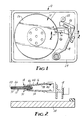
- FIGURE 1 is a top plan view of a data recording device including a recording head and support arm assembly of the present invention
- FIGURE 2 is a cross-sectional view of the data recording device of FIGURE 1, taken generally along the line 2-2 of FIGURE 1
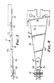
- FIGURE 3 is a side elevational view of the recording head and support arm assembly
- FIGURE 4 is a top plan view of the recording head and support arm assembly
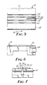
- FIGURE 5 is a bottom plan view of the recording head
- FIGURE 6 is a side elevational view of the recording head
- FIGURE 7 is an end elevational view of the recording head.
- FIGURE 1 illustrates a stretched surface recording (SSR) device, generally indicated as 10, which includes an SSR disk 12 which is rapidly rotated relative to a recording and playback head 14 which is mounted on a support arm 16 and radially traversed across the surface of the SSR disk 12 by a pivoting cue arm 18.
- the cue arm 18 is driven by a wire or ribbon 20 wrapped around a capstan 22, which capstan 22 is in turn driven by a stepper motor (not shown).
- the entire mechanism is supported by an enclosure 24 which contains electronics (not shown) controlling the recording and playback head 14 and a motor (not shown) for driving the SSR disk 12.
- the means for transporting the head is not part of the present invention, and the cue arm 18 could be replaced by another transport, such as a carriage moving on a linear track.
- the SSR disk 12 includes at least one thin polymeric film 26 which is suitably coated with a magnetic material (not shown) to enable the recording process.
- the thin film 26 is stretched across and bonded to a rigid polymeric substrate 28 which maintains the film 26 in tension and thus provides a flat, resilient recording surface.
- the substrate 28 may support a second thin polymeric film 30 and the cue arm 18 may support a second recording and playback head 32 mounted on a second support arm 34.
- the head 32 and the support arm 34 are identical to the head 14 and the support arm 16, respectively.
- the support arm 16 is manufactured by Brum-Ko Magnetics Corporation, Elkhorn, California, is best seen in FIGURES 3 and 4, and includes a mounting portion 36 which is rigidly attached to the cue arm 18 by means of two holes 39 which accept screws or bolts. Extending from the mounting portion 36 is a biasing portion 38 which is angled with respect to the mounting portion 36 by bending the support arm 16 along a fold line 40.
- the support arm 16 is shown in FIGURE 3 in approximately the position the arm 16 will assume in operation.
- the angle of bend between the biasing portion 38 and the mounting portion 36 is approximately 15 degrees when the support arm 16 is unloaded.
- the material of the support arm 16 is resilient stainless steel and a bend of approximately 15 degrees produces a load force at the end of the biasing portion 38 opposite the mounting portion 36 of approximately 0.10 Newton when the biasing portion 38 is in the operating position shown in FIGURE 3.
- the biasing portion 38 includes folded or rolled edges 42 and 44 which increase its rigidity.
- a stainless steel strip 46 which supports in turn a head attachment tab 48 which is formed by separating three of the edges of the head attachment tab 48 from the strip 46.
- the head attachment tab 48 is bent relative to the stainless steel strip 46 so that the attachment tab 48 is substantially parallel to the mounting portion 36 when the support arm 16 is positioned for operation.
- the stainless steel strip 46 and the biasing portion 38 include a hole 50 which is provided to guide wires (not shown) from the recording head 14 along the support arm 16.
- the overall length of the support arm 16 is approximately 32 mm and the width of the mounting portion 36 is approximately 10 mm.
- the recording and playback head 14 is attached to the head attachment tab 48 by means of an adhesive and is maintained free of contact between the recording head 14 and the stainless steel strip 46 and the biasing portion 38 of the support arm 16. As noted earlier, the attachment tab 48 maintains the recording head 14 substantially parallel to the mounting portion 36 when the support arm is in the operating position.
- the recording and playback head 14 is best illustrated in FIGURES 5-7 and is manufactured of a ceramic in a generally rectangular shape of approximately 3.2 mm by 4.3 mm.
- the surface 52 in proximity to the thin film 26 is spherical with a radius of approximately 102 mm. Cut into this spherical surface 52 are four grooves 54-60 which are substantially square in cross-section and are aligned with the direction of film 26 movement relative to the recording head 14.
- the direction of film 26 movement is illustrated by the arrow 62 in FIGURE 5.
- the width and depth of each groove 54-60 are approximately 0.15 mm and the separation between the outer grooves 54 and 60 and the inner grooves 56 and 58 is approximately 0.20 mm.
- the separation between the two inner grooves 56 and 58 is approximately 0.30 mm.
- the recording and playback head 14 is provided with a recording core 64 which is positioned within a slot 66 formed in the land between the inner grooves 56 and 58.
- the core 64 is maintained within the slot 66 by glass bonding and, as seen in FIGURE 5, is positioned approximately midway between the apex of the spherical surface 52 and the trailing edge 68 of the head 14 with respect to tape movement 62, with the gap of the core preferably located at least 0.50 mm from the trailing edge 68.
- the core 64 is positioned within the slot 66 so that its upper surface is even with the spherical surface 52.
- the grooves 54-60 in combination with the spherical surface 52 are provided to maintain a stable relationship between the recording head 14 and the stretched thin film 26 of the SSR disk 12.
- the film 26 remains flexible and is deformed into a depression or "dimple" in response to an applied load. This dimpling is advantageous, however, because it allows the thin film 26 to conform to the shape of the recording head 14 and thus reduces the gap distance between the thin film 26 and the recording core 64. Except when the SSR disk 12 is stationary, however, the recording head 14 is never actually in contact with the film 26.
- the spherical shape of the head surface 52 is chosen to provide a stable air bearing between the head 14 and the film 26. It has been found that a large spherical radius of the head surface 52 produces a wide and very stable air bearing between the head 14 and the film 26. Unfortunately, however, a large radius not only increases stability but also increases the flying height or separation between the head 14 and the film 26. A large separation is detrimental because the core 64 cannot adequately interact with the magnetic recording material found on the surface of the film 26. To reduce the separation between the head 14 and the film 26, the grooves 54-60 are provided which bleed air past the head 14 and decrease the height of the head 14 above the film 26 without disrupting the stability achieved by the large radius of the spherical surface 52.
- the recording head 14 is provided with a large spherical surface 52 to provide a stable air bearing cushion between the recording head 14 and the film 26 and the grooves 54-60 are provided to decrease the separation between the head 14 and the film 26 to a height which allows proper data transfer between the ferrite core 64 and the magnetic particles of the film 26.
- the relationship between the head 14 and the film 26 is also intimately affected by the characteristics of the support arm 16.
- the support arm 16 must provide a sufficient resilient biasing force between the head 14 and the film 26 to maintain the two in proximity, and must maintain the grooves 54-60 of the head 14 rigidly aligned with the direction of relative movement between the head 14 and the film 26.
- the support arm 16 must allow the recording head 14 to roll about an axis parallel to the direction of relative movement between the head 14 and the film 26 and pitch about an axis parallel to a radius of the SSR disk 12. These movements of the head 14 are necessary to allow the head 14 to compensate for transient conditions such as bumping of the recording device 10, dust and debris on the film 26 and increased or asymmetrical rigidity of the film as the rim of the SSR disk 12 is approached.
- the rigidity necessary to maintain the grooves 54-60 of the recording head 14 in alignment with the direction of travel relative to the film 26 is provided by the rolled or folded edges 42 and 44 of the biasing portion 38 of the support arm 16.
- the necessary limited freedom of the recording head 14 to roll and pitch is provided by attaching the recording head 14 to the attachment tab 48 of the support arm 16, which attachment tab 48 remains relatively flexible with respect to the support arm 16 by virtue of the fact that the head attachment tab 48 is connected to the remainder of the support arm 16 along only one edge. Bending of the head attachment tab 48 relative to the support arm 16 so that the head 14 is maintained substantially parallel to the mounting portion 36 of the support arm 16 also contributes to stability at the air bearing between the recording head spherical surface 52 and the film 26.
- the head 14 and support arm 16 configuration described has been found to operate suitably with an SSR disk 12 which has a film 26 tension of between about 500 and 900 Newtons per meter and which rotates to produce a velocity in excess of about 9.0 meters per second at the periphery of the disk 12.
- an SSR disk 12 which has a film 26 tension of between about 500 and 900 Newtons per meter and which rotates to produce a velocity in excess of about 9.0 meters per second at the periphery of the disk 12.
- the spherical radius of the head surface 52 will have to be increased and the spaces between the slots 54-60 will have to be decreased as tension of the film 26 increases. The converse is also true.
- the slots 54-60 will have to be narrowed or the spaces between the slots 54-60 will have to be increased to maintain the proper flying height. Increased velocities will only slightly increase the flying height.
- Stiffness of the polymeric film 26 material has little effect on performance, so long as the effect of film 26 tension dominates the effect of film 26 stiffness. If an inherently stiffer film 26 is utilized, the effect of this stiffness may be compensated for by decreasing the thickness of the film 26. For example, satisfactory performance has been achieved using a film 26 which has a modulus of elasticity of 4.8 ⁇ 109 Newtons per square meter and a thickness of 0.038 mm and a film which has a modulus of elasticity of 2.8 ⁇ 1010 Newtons per square meter and a thickness of 0.025 mm.
- edges between the slots 54-60 and the spherical surface 52 may be rounded rather than sharp as shown in FIGURE 7. The effect of such rounding has been found equivalent to increasing the width of the slots 54-60.
Landscapes
- Engineering & Computer Science (AREA)
- Manufacturing & Machinery (AREA)
- Supporting Of Heads In Record-Carrier Devices (AREA)
- Moving Of Heads (AREA)
- Common Mechanisms (AREA)
- Holding Or Fastening Of Disk On Rotational Shaft (AREA)
Priority Applications (1)
| Application Number | Priority Date | Filing Date | Title |
|---|---|---|---|
| AT86306402T ATE64026T1 (de) | 1985-08-22 | 1986-08-19 | Aufnahmekopf und tragarm fuer ein speichermedium mit gestreckter oberflaeche. |
Applications Claiming Priority (2)
| Application Number | Priority Date | Filing Date | Title |
|---|---|---|---|
| US76850985A | 1985-08-22 | 1985-08-22 | |
| US768509 | 1985-08-22 |
Publications (3)
| Publication Number | Publication Date |
|---|---|
| EP0213875A2 EP0213875A2 (en) | 1987-03-11 |
| EP0213875A3 EP0213875A3 (en) | 1987-11-11 |
| EP0213875B1 true EP0213875B1 (en) | 1991-05-29 |
Family
ID=25082707
Family Applications (1)
| Application Number | Title | Priority Date | Filing Date |
|---|---|---|---|
| EP86306402A Expired - Lifetime EP0213875B1 (en) | 1985-08-22 | 1986-08-19 | Recording head and support arm for stretched surface recording medium |
Country Status (5)
| Country | Link |
|---|---|
| EP (1) | EP0213875B1 (ko) |
| JP (1) | JPS6235448U (ko) |
| KR (1) | KR930001102Y1 (ko) |
| AT (1) | ATE64026T1 (ko) |
| DE (1) | DE3679480D1 (ko) |
Citations (1)
| Publication number | Priority date | Publication date | Assignee | Title |
|---|---|---|---|---|
| US3537083A (en) * | 1968-11-27 | 1970-10-27 | Univ Illinois | Flexible surface disc for magnetic recorders with central pneumatic orifice |
Family Cites Families (7)
| Publication number | Priority date | Publication date | Assignee | Title |
|---|---|---|---|---|
| JPS6023966B2 (ja) * | 1976-09-22 | 1985-06-10 | 旭化成株式会社 | ペンシル形沓付パイルの製造方法 |
| US4167765A (en) * | 1978-07-27 | 1979-09-11 | International Business Machines Corporation | Transducer suspension mount apparatus |
| JPS5927986B2 (ja) * | 1980-01-25 | 1984-07-10 | 日本電信電話株式会社 | 浮上形ヘツド |
| US4375656A (en) * | 1980-10-09 | 1983-03-01 | International Business Machines Corporation | Magnetic head assembly with asymmetric slotted configuration |
| JPS5788572A (en) * | 1980-11-21 | 1982-06-02 | Nippon Telegr & Teleph Corp <Ntt> | Floating head supporting mechanism |
| JPS59180855A (ja) * | 1983-03-30 | 1984-10-15 | インタ−ナシヨナル ビジネス マシ−ンズ コ−ポレ−シヨン | ヘッドサスペンション装置付きディスク・ファイル |
| JPS6050778A (ja) * | 1983-08-31 | 1985-03-20 | Fujitsu Ltd | 磁気ヘッド支持機構 |
-
1986
- 1986-08-19 EP EP86306402A patent/EP0213875B1/en not_active Expired - Lifetime
- 1986-08-19 DE DE8686306402T patent/DE3679480D1/de not_active Expired - Fee Related
- 1986-08-19 AT AT86306402T patent/ATE64026T1/de not_active IP Right Cessation
- 1986-08-20 JP JP1986125936U patent/JPS6235448U/ja active Pending
- 1986-08-21 KR KR2019860012680U patent/KR930001102Y1/ko not_active IP Right Cessation
Patent Citations (1)
| Publication number | Priority date | Publication date | Assignee | Title |
|---|---|---|---|---|
| US3537083A (en) * | 1968-11-27 | 1970-10-27 | Univ Illinois | Flexible surface disc for magnetic recorders with central pneumatic orifice |
Also Published As
| Publication number | Publication date |
|---|---|
| KR930001102Y1 (ko) | 1993-03-11 |
| DE3679480D1 (de) | 1991-07-04 |
| KR870004307U (ko) | 1987-07-31 |
| ATE64026T1 (de) | 1991-06-15 |
| JPS6235448U (ko) | 1987-03-02 |
| EP0213875A3 (en) | 1987-11-11 |
| EP0213875A2 (en) | 1987-03-11 |
Similar Documents
| Publication | Publication Date | Title |
|---|---|---|
| US5896246A (en) | Suspension fabricated from silicon | |
| US4663682A (en) | Apparatus for loading and unloading a magnetic head assembly on a magnetic recording surface | |
| US7057857B1 (en) | Dimple pivot post for a rotary co-located microactuator | |
| EP0338698B1 (en) | A transducer head suspension assembly | |
| US6515832B1 (en) | Gimbal stiffness control for head suspension assemblies | |
| US5856896A (en) | Gimbal suspension for supporting a head in a disc drive assembly | |
| US5877920A (en) | Head suspension assembly with displacement limiter | |
| US6151197A (en) | Water slide suspension assembly having a stiffened vertically offset lift tab | |
| EP0897575B1 (en) | A multi-piece integrated suspension assembly for a magnetic storage system | |
| US7701673B2 (en) | Gimbal design with solder ball bond pads and trailing edge limiter tab for a recording head | |
| US5657188A (en) | Head suspension with tracking microactuator | |
| US5570261A (en) | Transducer suspension system | |
| US6243235B1 (en) | Transducer suspension system with limiter | |
| US20010050833A1 (en) | Combined servo-tracking and preload-controlling microactuator | |
| US5063464A (en) | Low profile suspension | |
| US5612841A (en) | Flexure assembly for hard disc drive heads | |
| US4809104A (en) | Recording head and support arm for stretched surface recording medium | |
| US5734525A (en) | Head suspension with torsion spring region | |
| US4422115A (en) | Lightweight dual head support assembly for magnetic disk drives | |
| US4879618A (en) | Wind breaking assembly for a magnetic head | |
| EP0278506B1 (en) | Head slider supporting mechanism for a magnetic disk apparatus | |
| KR900004760B1 (ko) | 자기디스크장치의 자기헤드 지지기구 | |
| US4876623A (en) | Magnetic disc device with gimbal spring having variable elastic characteristics | |
| US6417996B1 (en) | Gimbal for a head of a disc drive with vertical limiter | |
| EP0093711A1 (en) | Magnetic head loading and retraction apparatus |
Legal Events
| Date | Code | Title | Description |
|---|---|---|---|
| PUAI | Public reference made under article 153(3) epc to a published international application that has entered the european phase |
Free format text: ORIGINAL CODE: 0009012 |
|
| AK | Designated contracting states |
Kind code of ref document: A2 Designated state(s): AT DE FR GB IT NL |
|
| PUAL | Search report despatched |
Free format text: ORIGINAL CODE: 0009013 |
|
| AK | Designated contracting states |
Kind code of ref document: A3 Designated state(s): AT DE FR GB IT NL |
|
| 17P | Request for examination filed |
Effective date: 19880331 |
|
| 17Q | First examination report despatched |
Effective date: 19891110 |
|
| ITF | It: translation for a ep patent filed | ||
| GRAA | (expected) grant |
Free format text: ORIGINAL CODE: 0009210 |
|
| AK | Designated contracting states |
Kind code of ref document: B1 Designated state(s): AT DE FR GB IT NL |
|
| REF | Corresponds to: |
Ref document number: 64026 Country of ref document: AT Date of ref document: 19910615 Kind code of ref document: T |
|
| REF | Corresponds to: |
Ref document number: 3679480 Country of ref document: DE Date of ref document: 19910704 |
|
| ET | Fr: translation filed | ||
| PLBE | No opposition filed within time limit |
Free format text: ORIGINAL CODE: 0009261 |
|
| STAA | Information on the status of an ep patent application or granted ep patent |
Free format text: STATUS: NO OPPOSITION FILED WITHIN TIME LIMIT |
|
| 26N | No opposition filed | ||
| PGFP | Annual fee paid to national office [announced via postgrant information from national office to epo] |
Ref country code: FR Payment date: 19940712 Year of fee payment: 9 |
|
| PGFP | Annual fee paid to national office [announced via postgrant information from national office to epo] |
Ref country code: AT Payment date: 19940718 Year of fee payment: 9 |
|
| PGFP | Annual fee paid to national office [announced via postgrant information from national office to epo] |
Ref country code: DE Payment date: 19940725 Year of fee payment: 9 |
|
| PGFP | Annual fee paid to national office [announced via postgrant information from national office to epo] |
Ref country code: GB Payment date: 19940728 Year of fee payment: 9 |
|
| PGFP | Annual fee paid to national office [announced via postgrant information from national office to epo] |
Ref country code: NL Payment date: 19940831 Year of fee payment: 9 |
|
| PG25 | Lapsed in a contracting state [announced via postgrant information from national office to epo] |
Ref country code: GB Effective date: 19950819 Ref country code: AT Effective date: 19950819 |
|
| PG25 | Lapsed in a contracting state [announced via postgrant information from national office to epo] |
Ref country code: NL Effective date: 19960301 |
|
| GBPC | Gb: european patent ceased through non-payment of renewal fee |
Effective date: 19950819 |
|
| PG25 | Lapsed in a contracting state [announced via postgrant information from national office to epo] |
Ref country code: FR Effective date: 19960430 |
|
| NLV4 | Nl: lapsed or anulled due to non-payment of the annual fee |
Effective date: 19960301 |
|
| PG25 | Lapsed in a contracting state [announced via postgrant information from national office to epo] |
Ref country code: DE Effective date: 19960501 |
|
| REG | Reference to a national code |
Ref country code: FR Ref legal event code: ST |
|
| PG25 | Lapsed in a contracting state [announced via postgrant information from national office to epo] |
Ref country code: IT Free format text: LAPSE BECAUSE OF NON-PAYMENT OF DUE FEES;WARNING: LAPSES OF ITALIAN PATENTS WITH EFFECTIVE DATE BEFORE 2007 MAY HAVE OCCURRED AT ANY TIME BEFORE 2007. THE CORRECT EFFECTIVE DATE MAY BE DIFFERENT FROM THE ONE RECORDED. Effective date: 20050819 |