EP0213699A2 - Appareil d'assemblage d'un tube et d'une plaque tubulaire, le tube étant expansé par explosion et comprenant un tube de confinement - Google Patents
Appareil d'assemblage d'un tube et d'une plaque tubulaire, le tube étant expansé par explosion et comprenant un tube de confinement Download PDFInfo
- Publication number
- EP0213699A2 EP0213699A2 EP86305140A EP86305140A EP0213699A2 EP 0213699 A2 EP0213699 A2 EP 0213699A2 EP 86305140 A EP86305140 A EP 86305140A EP 86305140 A EP86305140 A EP 86305140A EP 0213699 A2 EP0213699 A2 EP 0213699A2
- Authority
- EP
- European Patent Office
- Prior art keywords
- tube
- force
- barrier
- transmitting member
- explosive
- Prior art date
- Legal status (The legal status is an assumption and is not a legal conclusion. Google has not performed a legal analysis and makes no representation as to the accuracy of the status listed.)
- Withdrawn
Links
Images
Classifications
-
- F—MECHANICAL ENGINEERING; LIGHTING; HEATING; WEAPONS; BLASTING
- F28—HEAT EXCHANGE IN GENERAL
- F28F—DETAILS OF HEAT-EXCHANGE AND HEAT-TRANSFER APPARATUS, OF GENERAL APPLICATION
- F28F9/00—Casings; Header boxes; Auxiliary supports for elements; Auxiliary members within casings
- F28F9/02—Header boxes; End plates
- F28F9/04—Arrangements for sealing elements into header boxes or end plates
- F28F9/16—Arrangements for sealing elements into header boxes or end plates by permanent joints, e.g. by rolling
-
- F—MECHANICAL ENGINEERING; LIGHTING; HEATING; WEAPONS; BLASTING
- F28—HEAT EXCHANGE IN GENERAL
- F28F—DETAILS OF HEAT-EXCHANGE AND HEAT-TRANSFER APPARATUS, OF GENERAL APPLICATION
- F28F2275/00—Fastening; Joining
- F28F2275/06—Fastening; Joining by welding
- F28F2275/068—Fastening; Joining by welding by explosive welding
-
- Y—GENERAL TAGGING OF NEW TECHNOLOGICAL DEVELOPMENTS; GENERAL TAGGING OF CROSS-SECTIONAL TECHNOLOGIES SPANNING OVER SEVERAL SECTIONS OF THE IPC; TECHNICAL SUBJECTS COVERED BY FORMER USPC CROSS-REFERENCE ART COLLECTIONS [XRACs] AND DIGESTS
- Y10—TECHNICAL SUBJECTS COVERED BY FORMER USPC
- Y10S—TECHNICAL SUBJECTS COVERED BY FORMER USPC CROSS-REFERENCE ART COLLECTIONS [XRACs] AND DIGESTS
- Y10S72/00—Metal deforming
- Y10S72/706—Explosive
-
- Y—GENERAL TAGGING OF NEW TECHNOLOGICAL DEVELOPMENTS; GENERAL TAGGING OF CROSS-SECTIONAL TECHNOLOGIES SPANNING OVER SEVERAL SECTIONS OF THE IPC; TECHNICAL SUBJECTS COVERED BY FORMER USPC CROSS-REFERENCE ART COLLECTIONS [XRACs] AND DIGESTS
- Y10—TECHNICAL SUBJECTS COVERED BY FORMER USPC
- Y10T—TECHNICAL SUBJECTS COVERED BY FORMER US CLASSIFICATION
- Y10T29/00—Metal working
- Y10T29/49—Method of mechanical manufacture
- Y10T29/4935—Heat exchanger or boiler making
- Y10T29/49373—Tube joint and tube plate structure
- Y10T29/49375—Tube joint and tube plate structure including conduit expansion or inflation
-
- Y—GENERAL TAGGING OF NEW TECHNOLOGICAL DEVELOPMENTS; GENERAL TAGGING OF CROSS-SECTIONAL TECHNOLOGIES SPANNING OVER SEVERAL SECTIONS OF THE IPC; TECHNICAL SUBJECTS COVERED BY FORMER USPC CROSS-REFERENCE ART COLLECTIONS [XRACs] AND DIGESTS
- Y10—TECHNICAL SUBJECTS COVERED BY FORMER USPC
- Y10T—TECHNICAL SUBJECTS COVERED BY FORMER US CLASSIFICATION
- Y10T29/00—Metal working
- Y10T29/49—Method of mechanical manufacture
- Y10T29/49805—Shaping by direct application of fluent pressure
- Y10T29/49806—Explosively shaping
-
- Y—GENERAL TAGGING OF NEW TECHNOLOGICAL DEVELOPMENTS; GENERAL TAGGING OF CROSS-SECTIONAL TECHNOLOGIES SPANNING OVER SEVERAL SECTIONS OF THE IPC; TECHNICAL SUBJECTS COVERED BY FORMER USPC CROSS-REFERENCE ART COLLECTIONS [XRACs] AND DIGESTS
- Y10—TECHNICAL SUBJECTS COVERED BY FORMER USPC
- Y10T—TECHNICAL SUBJECTS COVERED BY FORMER US CLASSIFICATION
- Y10T29/00—Metal working
- Y10T29/51—Plural diverse manufacturing apparatus including means for metal shaping or assembling
- Y10T29/5199—Work on tubes
-
- Y—GENERAL TAGGING OF NEW TECHNOLOGICAL DEVELOPMENTS; GENERAL TAGGING OF CROSS-SECTIONAL TECHNOLOGIES SPANNING OVER SEVERAL SECTIONS OF THE IPC; TECHNICAL SUBJECTS COVERED BY FORMER USPC CROSS-REFERENCE ART COLLECTIONS [XRACs] AND DIGESTS
- Y10—TECHNICAL SUBJECTS COVERED BY FORMER USPC
- Y10T—TECHNICAL SUBJECTS COVERED BY FORMER US CLASSIFICATION
- Y10T29/00—Metal working
- Y10T29/53—Means to assemble or disassemble
- Y10T29/53113—Heat exchanger
- Y10T29/53122—Heat exchanger including deforming means
-
- Y—GENERAL TAGGING OF NEW TECHNOLOGICAL DEVELOPMENTS; GENERAL TAGGING OF CROSS-SECTIONAL TECHNOLOGIES SPANNING OVER SEVERAL SECTIONS OF THE IPC; TECHNICAL SUBJECTS COVERED BY FORMER USPC CROSS-REFERENCE ART COLLECTIONS [XRACs] AND DIGESTS
- Y10—TECHNICAL SUBJECTS COVERED BY FORMER USPC
- Y10T—TECHNICAL SUBJECTS COVERED BY FORMER US CLASSIFICATION
- Y10T29/00—Metal working
- Y10T29/53—Means to assemble or disassemble
- Y10T29/53996—Means to assemble or disassemble by deforming
Definitions
- This invention relates to an apparatus for explosively forming a tube into a bore formed in a tube sheet, and more particularly, to such an apparatus utilizing an explosive which is placed within the tube to be expanded.
- heat exchangers feature the use of a plurality of heat exchange tubes disposed within bores extending through a tube sheet.
- the tubes receive a primary fluid which is passed through the tubes in a heat exchange relationship with a secondary fluid passing over the tubes.
- the tubes have been mechanically expanded into the tube sheets utilizing a mandrel or the like, or by rolling, i.e., by applying an outward radial force against the entire surface of the tubes.
- these techniques enjoy several disadvantages including local metal deformation, general lengthening of the tubes, and the application of axial stresses on the tube weld and compressive strains in the tube wall.
- an explosive charge is disposed within the area of overlap between the tubes and the tube sheet and is surrounded by a force-transmitting member which, upon detonation of the explosive charge, expands the tube uniformly against the inner wall of the tube sheet.
- the apparatus of the present invention utilizes a tubular force-transmitting member that extends within said tube coextensive with the portion of the tube to be expanded.
- the forces resulting from the explosion of an explosive placed within the force-transmitting member are uniformly transferred to the tube to expand the tube.
- a barrier tube extends between the said force-transmitting member and the tube and has a portion projecting from the tube sheet.
- a plug is disposed in the end of the projecting portion of the barrier tube to contain the debris and gases resulting from the explosion.
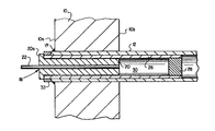
- the reference numeral 10 refers in general to a tube sheet which can form a portion of a heat exchanger having a plurality of heat exchange tubes, one of which is shown by the reference numeral 12.
- Each tube 12 extends within a corresponding bore formed with the tube sheet 10, with one end of each of the tubes extending immediately adjacent the outer surface 10a of the tube sheet. The other end of the tube 12 projects from the inner surface 10b of the tube sheet and extends into the interior of the heat exchanger.
- the outer diameter of the tube 12 is slightly less than the inner diameter of the tube sheet bore and the tube is secured to the outer surface 10a of the tube sheet 10 by an annular weldment 14. Only a portion of the tube 12 is shown in the interest of clarity, it being understood that the heat exchanger would also include a vessel enclosing the tube sheet and having suitable inlets and outlets for a primary heat exchange fluid and a secondary heat exchange fluid. According to a typical arrangement of this type, each tube 12 would be U-shaped, with both ends of the tube extending through the tube sheet 10. The primary heat exchange fluid enters each tube 12 through the end shown adjacent the outer surface 10a of the tube sheet 10, passes through the tube in a heat exchange relation with a secondary fluid passing through the vessel to the right of the tube sheet, and exits through the other end of the tube.
- the tube 12 is depicted in the drawing prior to it being explosively formed in the tube sheet 10, along with the apparatus of the present invention for effecting the explosive forming.
- the latter apparatus includes an insert, shown in general by the reference numeral 18, which extends within that portion of the tube 12-extending coextensively with the tube sheet 10.
- the insert 18 consists of a generally tubular force-transmitting member 20 and a rod-shaped explosive member 22 extending within the bore of the force-transmitting member 20.
- the force-transmitting member 20 has an outside diameter which is less than the inner diameter of the tube 12, and one end of the force-transmitting member 20 extends flush with the inner surface 10b of the tube sheet 10, while the other end projects slightly from the outer surface 10a of the tube sheet.
- a shoulder 20a is provided on the projecting end of the force-transmitting member 20 for reasons that will be described later.
- the explosive member 22 contains a determined number of grains of explosive distributed uniformly along its axis. One end of the explosive member 22 extends flush with the corresponding end of the force-transmitting member 20 and with the inner surface 10b of the tube sheet 10. The other end of the explosive member 22 projects from the corresponding end of the force-transmitting member 20 and is connected to an energy transfer cord or the-like (not shown) which connects a detonator cap (not shown) with the explosive member 22 for igniting it, in a conventional manner.
- a barrier tube 26 is provided within the tube 12 and has a first portion extending between the force-transmitting member 20 and the inner wall of the tube 12, and another portion projecting from the inner surface of 10b of the tube sheet 10 for a distance corresponding approximately to the width of the tube sheet.
- One end of the barrier tube 26 engages the shoulder 20a of the force-transmitting member 20, and an end plug 28 is disposed within the other end of the barrier tube.
- a chamber 30 is thus defined by the barrier tube 26 and the corresponding surfaces of the force-transmitting member 20 and the end plug 28.
- a collar 32 extends between the shoulder 20a and the tube 12 to precisely locate the force-transmitting member 20, and therefore the barrier tube 26, relative to the tube 12.
- the force-transmitting member 20 can be fabricated from a low cost plastic material having good energy transmission characteristics, such as polyethylene; while the barrier tube 26 can be of a high strength and impact resistant material such as fluroplastic, nylon, polyurethane elastomer, or the like.
- the thickness of the wall of the barrier tube 26 is less than that of the force-transmitting member 20 so that its lower energy transmission characteristics are minimized, but is great enough to withstand the impact of the explosive forces.
- the force-transmitting member 20 and the barrier tube 26 can be fabricated separately by any know plastic processing method or, alternatively, can be coextruded with the barrier tube 26 being extruded over the force-transmitting member in one operation.
- the explosive member 22 is detonated in the manner discussed above and the resulting forces are transmitted, via the force-transmitting member 20 and through the tube 26, uniformly to the tube 12 to cause a uniform expansion of the tube against the,wall portion of the bore in the tube sheet 10.
- the high strength characteristics of the barrier tube 26 prevent it from fracturing, and the gases and debris resulting from the explosion are thus contained in the chamber 20, preventing any contamination in the interior of the heat exchanger.
Landscapes
- Engineering & Computer Science (AREA)
- Physics & Mathematics (AREA)
- Thermal Sciences (AREA)
- Mechanical Engineering (AREA)
- General Engineering & Computer Science (AREA)
- Lining Or Joining Of Plastics Or The Like (AREA)
- Pressure Welding/Diffusion-Bonding (AREA)
Applications Claiming Priority (2)
| Application Number | Priority Date | Filing Date | Title |
|---|---|---|---|
| US06/768,997 US4685205A (en) | 1985-08-26 | 1985-08-26 | Apparatus for forming an explosively expanded tube-tube sheet joint including a barrier tube |
| US768997 | 1985-08-26 |
Publications (2)
| Publication Number | Publication Date |
|---|---|
| EP0213699A2 true EP0213699A2 (fr) | 1987-03-11 |
| EP0213699A3 EP0213699A3 (fr) | 1987-09-30 |
Family
ID=25084104
Family Applications (1)
| Application Number | Title | Priority Date | Filing Date |
|---|---|---|---|
| EP86305140A Withdrawn EP0213699A3 (fr) | 1985-08-26 | 1986-07-02 | Appareil d'assemblage d'un tube et d'une plaque tubulaire, le tube étant expansé par explosion et comprenant un tube de confinement |
Country Status (2)
| Country | Link |
|---|---|
| US (1) | US4685205A (fr) |
| EP (1) | EP0213699A3 (fr) |
Cited By (1)
| Publication number | Priority date | Publication date | Assignee | Title |
|---|---|---|---|---|
| FR2844587A1 (fr) * | 2002-09-17 | 2004-03-19 | Framatome Anp | Procede de mise en precontrainte de tubes d'un echangeur de chaleur avec un reglage precis de la precontrainte |
Families Citing this family (6)
| Publication number | Priority date | Publication date | Assignee | Title |
|---|---|---|---|---|
| CH670656A5 (fr) * | 1987-04-14 | 1989-06-30 | Fischer Ag Georg | |
| GB8721985D0 (en) * | 1987-09-18 | 1987-10-28 | Ici Plc | Explosive expansion of metal tubes |
| EP0392051B1 (fr) * | 1989-04-12 | 1994-08-31 | Siemens Aktiengesellschaft | Procédé et dispositif pour attacher une broche de centrage |
| SE500136C2 (sv) * | 1992-03-11 | 1994-04-25 | Exploweld Ab | Anordning för inklädnad av rör medelst explosionsformning |
| US5406686A (en) * | 1994-02-18 | 1995-04-18 | Hochstein; Peter A. | Deflagration apparatus for making a cam shaft |
| NL2011608C2 (nl) * | 2013-10-14 | 2015-06-16 | Synex Tube B V | Werkwijze voor het door middel van explosielassen aan elkaar bevestigen van ten minste twee metalen werkstukdelen. |
Family Cites Families (19)
| Publication number | Priority date | Publication date | Assignee | Title |
|---|---|---|---|---|
| US3206845A (en) * | 1963-01-16 | 1965-09-21 | Joseph R Crump | Apparatus for joining pipe sections |
| FR1422388A (fr) * | 1964-12-02 | 1965-12-24 | Siemens Ag | Procédé d'assemblage d'éléments tubulaires de construction |
| CH425358A (de) * | 1966-06-06 | 1966-11-30 | Exnii Metallorezh Stankov | Schwingungsdämpfende Stützunterlage |
| US3555656A (en) * | 1967-05-25 | 1971-01-19 | Westinghouse Electric Corp | Method of explosively plugging a leaky metal tube in a heat exchanger tube bundle |
| US3566646A (en) * | 1968-04-18 | 1971-03-02 | Richard W Walkup | Explosive attachment apparatus |
| US3562887A (en) * | 1968-05-08 | 1971-02-16 | Foster Wheeler Corp | Explosive expansion of liner sleeves |
| US3590877A (en) * | 1968-09-20 | 1971-07-06 | Babcock & Wilcox Co | Explosive-activated plug |
| US3790060A (en) * | 1969-09-23 | 1974-02-05 | Sulzer Ag | Apparatus for mounting a pipe in a perforated plate |
| BE756406A (fr) * | 1969-09-23 | 1971-03-22 | Sulzer Ag | Procede de fixation d'un tube dans une plaque perforee par ondes de pression produites par explosion et disposition pour la miseen oeuvre de ce procede |
| US3661004A (en) * | 1969-11-07 | 1972-05-09 | Atlas Chem Ind | Explosive tubing swager |
| DE2124530C3 (de) * | 1971-05-18 | 1978-04-27 | Siemens Ag, 1000 Berlin Und 8000 Muenchen | Einrichtung zum Verschließen schadhafter Wärmetauseherrohre |
| DE2241753C3 (de) * | 1972-08-25 | 1982-03-25 | Siemens AG, 1000 Berlin und 8000 München | Einrichtung zum Verschließen schadhafter Wärmetauscherrohre |
| US3797098A (en) * | 1972-09-14 | 1974-03-19 | Nasa | Totally confined explosive welding |
| US3993001A (en) * | 1975-08-18 | 1976-11-23 | Tetra Plastics, Inc. | Explosive expansion means for attaching tubes to tube sheets |
| US4030419A (en) * | 1975-11-20 | 1977-06-21 | Westinghouse Electric Corporation | Insert for explosively expanding a tube into engagement with a tube sheet |
| US4028789A (en) * | 1976-03-29 | 1977-06-14 | Westinghouse Electric Corporation | Method of installing a sleeve in one end of a tube |
| US4205422A (en) * | 1977-06-15 | 1980-06-03 | Yorkshire Imperial Metals Limited | Tube repairs |
| US4117966A (en) * | 1977-10-13 | 1978-10-03 | The United States Of America As Represented By The United States Department Of Energy | Explosive welding of a tube into a tube sheet |
| JPS59183942A (ja) * | 1983-02-22 | 1984-10-19 | フオスタ−・ホイ−ラ−・エナ−ジイ・コ−ポレイシヨン | 閉鎖端を有する補強繊維入り力伝達部材を備えた爆薬式管拡張装置 |
-
1985
- 1985-08-26 US US06/768,997 patent/US4685205A/en not_active Expired - Lifetime
-
1986
- 1986-07-02 EP EP86305140A patent/EP0213699A3/fr not_active Withdrawn
Cited By (1)
| Publication number | Priority date | Publication date | Assignee | Title |
|---|---|---|---|---|
| FR2844587A1 (fr) * | 2002-09-17 | 2004-03-19 | Framatome Anp | Procede de mise en precontrainte de tubes d'un echangeur de chaleur avec un reglage precis de la precontrainte |
Also Published As
| Publication number | Publication date |
|---|---|
| US4685205A (en) | 1987-08-11 |
| EP0213699A3 (fr) | 1987-09-30 |
Similar Documents
| Publication | Publication Date | Title |
|---|---|---|
| US4494392A (en) | Apparatus for forming an explosively expanded tube-tube sheet joint including a low energy transfer cord and booster | |
| US3781966A (en) | Method of explosively expanding sleeves in eroded tubes | |
| US3590877A (en) | Explosive-activated plug | |
| US3562887A (en) | Explosive expansion of liner sleeves | |
| EP0079716B1 (fr) | Dilatation d'un tube par explosion | |
| US3411198A (en) | Explosive expansion of tubes into tube sheets | |
| US4685205A (en) | Apparatus for forming an explosively expanded tube-tube sheet joint including a barrier tube | |
| US3698067A (en) | Method for mounting a pipe in a perforated plate | |
| US3724062A (en) | Explosively welded plug for leaky tubes of a heat exchanger and method of using the same | |
| US5479961A (en) | Method of plugging a heat exchanger tube and plug therefor | |
| EP0117153B1 (fr) | Dispositif pour former une jonction entre les parois de tubes par expansion à cause d'explosion utilisant un insert renforcé par des fibres et ayant un bout fermé | |
| US4518111A (en) | Method of fabricating a bi-metal tube | |
| US3543370A (en) | Method and apparatus for explosively forming a tube within a tube sheet | |
| US4347790A (en) | Explosive plug for blocking tubes | |
| EP0309084B1 (fr) | Jonction de tuyaux en métal | |
| US4587904A (en) | Debris free plug assembly for heat exchange tubes | |
| US5022148A (en) | Method for explosively welding a sleeve into a heat exchanger tube | |
| Schroeder | Apparatus for forming an explosively expanded tube-tube sheet joint | |
| US5038994A (en) | Apparatus for explosively welding a sleeve into a heat exchanger tube | |
| US4641774A (en) | Fixture for explosively welding a tube to a tubesheet | |
| EP0381880B1 (fr) | Soudage par explosion des manchons sur les surfaces intérieures des tubes | |
| WO1987001428A1 (fr) | Procede de raccordement de longueurs de tuyaux, raccord ainsi produit, et longueurs de tuyaux fabriquees par ce procede | |
| US3611767A (en) | Explosive forming of inner cylinders into outer cylinders | |
| EP0102188A3 (fr) | Bouchon à l'explosif pour réparer des tubes d'échangeurs de chaleur | |
| CA1320821C (fr) | Methode et appareil de soudage par explosifs d'un manchon sur un tube d'echangeur de chaleur |
Legal Events
| Date | Code | Title | Description |
|---|---|---|---|
| PUAI | Public reference made under article 153(3) epc to a published international application that has entered the european phase |
Free format text: ORIGINAL CODE: 0009012 |
|
| AK | Designated contracting states |
Kind code of ref document: A2 Designated state(s): DE FR GB |
|
| PUAL | Search report despatched |
Free format text: ORIGINAL CODE: 0009013 |
|
| RHK1 | Main classification (correction) |
Ipc: B21D 39/06 |
|
| AK | Designated contracting states |
Kind code of ref document: A3 Designated state(s): DE FR GB |
|
| 17P | Request for examination filed |
Effective date: 19880322 |
|
| 17Q | First examination report despatched |
Effective date: 19890621 |
|
| STAA | Information on the status of an ep patent application or granted ep patent |
Free format text: STATUS: THE APPLICATION IS DEEMED TO BE WITHDRAWN |
|
| 18D | Application deemed to be withdrawn |
Effective date: 19901005 |
|
| RIN1 | Information on inventor provided before grant (corrected) |
Inventor name: SCHROEDER, JOSEPH W. Inventor name: AHLUWALIA, KAWALJIT S. |