EP0213265B1 - Workpiece centering apparatus and method - Google Patents
Workpiece centering apparatus and method Download PDFInfo
- Publication number
- EP0213265B1 EP0213265B1 EP86103306A EP86103306A EP0213265B1 EP 0213265 B1 EP0213265 B1 EP 0213265B1 EP 86103306 A EP86103306 A EP 86103306A EP 86103306 A EP86103306 A EP 86103306A EP 0213265 B1 EP0213265 B1 EP 0213265B1
- Authority
- EP
- European Patent Office
- Prior art keywords
- workpiece
- edge
- image
- transport surface
- fabric
- Prior art date
- Legal status (The legal status is an assumption and is not a legal conclusion. Google has not performed a legal analysis and makes no representation as to the accuracy of the status listed.)
- Expired
Links
- 238000000034 method Methods 0.000 title claims description 7
- 239000004744 fabric Substances 0.000 claims description 37
- 230000003287 optical effect Effects 0.000 claims description 4
- 239000013307 optical fiber Substances 0.000 claims 1
- 230000007246 mechanism Effects 0.000 description 4
- 239000000835 fiber Substances 0.000 description 3
- 238000004519 manufacturing process Methods 0.000 description 2
- 230000001419 dependent effect Effects 0.000 description 1
- 239000000463 material Substances 0.000 description 1
- 238000009958 sewing Methods 0.000 description 1
Images
Classifications
-
- B—PERFORMING OPERATIONS; TRANSPORTING
- B23—MACHINE TOOLS; METAL-WORKING NOT OTHERWISE PROVIDED FOR
- B23Q—DETAILS, COMPONENTS, OR ACCESSORIES FOR MACHINE TOOLS, e.g. ARRANGEMENTS FOR COPYING OR CONTROLLING; MACHINE TOOLS IN GENERAL CHARACTERISED BY THE CONSTRUCTION OF PARTICULAR DETAILS OR COMPONENTS; COMBINATIONS OR ASSOCIATIONS OF METAL-WORKING MACHINES, NOT DIRECTED TO A PARTICULAR RESULT
- B23Q17/00—Arrangements for observing, indicating or measuring on machine tools
- B23Q17/24—Arrangements for observing, indicating or measuring on machine tools using optics or electromagnetic waves
-
- A—HUMAN NECESSITIES
- A41—WEARING APPAREL
- A41H—APPLIANCES OR METHODS FOR MAKING CLOTHES, e.g. FOR DRESS-MAKING OR FOR TAILORING, NOT OTHERWISE PROVIDED FOR
- A41H43/00—Other methods, machines or appliances
- A41H43/02—Handling garment parts or blanks, e.g. feeding, piling, separating or reversing
- A41H43/0271—Registering
-
- B—PERFORMING OPERATIONS; TRANSPORTING
- B23—MACHINE TOOLS; METAL-WORKING NOT OTHERWISE PROVIDED FOR
- B23Q—DETAILS, COMPONENTS, OR ACCESSORIES FOR MACHINE TOOLS, e.g. ARRANGEMENTS FOR COPYING OR CONTROLLING; MACHINE TOOLS IN GENERAL CHARACTERISED BY THE CONSTRUCTION OF PARTICULAR DETAILS OR COMPONENTS; COMBINATIONS OR ASSOCIATIONS OF METAL-WORKING MACHINES, NOT DIRECTED TO A PARTICULAR RESULT
- B23Q3/00—Devices holding, supporting, or positioning work or tools, of a kind normally removable from the machine
- B23Q3/18—Devices holding, supporting, or positioning work or tools, of a kind normally removable from the machine for positioning only
- B23Q3/183—Centering devices
-
- G—PHYSICS
- G01—MEASURING; TESTING
- G01B—MEASURING LENGTH, THICKNESS OR SIMILAR LINEAR DIMENSIONS; MEASURING ANGLES; MEASURING AREAS; MEASURING IRREGULARITIES OF SURFACES OR CONTOURS
- G01B11/00—Measuring arrangements characterised by the use of optical techniques
- G01B11/02—Measuring arrangements characterised by the use of optical techniques for measuring length, width or thickness
Definitions
- the apparatus of this invention relates generally to the garment industry but is not limited thereto, and in particular it relates to an apparatus and method for aiding an operator or a machine in dividing a piece of fabric or other material about a reference line, such as the centerline of the fabric.
- the apparatus is particularly useful when the fabric to be divided is by design or tolerance of a variable width.
- a workpiece be divided, folded, or located along its theoretical centerline prior to the introduction of the workpiece to a work station for sewing for for affixing (stitching) fabric pieces, such as pockets, zippers, etc.
- affixing stitching
- the workpiece is of variable width, as is often the case, it is quite difficult and time consuming to align the workpiece with a desired reference line, such as the centerline, and to maintain that alignment using known devices.
- the prior art devices used for this purpose become even more time consuming and difficult to manage, and thus less efficient when the volume of the fabric to be worked on is great, such as is the case in large garment (i.e. pants and shirts) manufacturing plants.
- the known prior art devices serving this purpose consist of mechanical guiders which are designed to span the width of the fabric.
- mechanical means must be constantly changed and adjusted to accept different sizes of workpieces.
- Such means are obviously undersirable, particularly in large garment manufacturing plants, since these mechanisms are unable to give accurate dimensional repeatability.
- Such adjustments are avoided with the apparatus of the present invention.
- automated devices such as robots and/or servo driven mechanisms often need width measuring sensors and adjustable mounts to accommodate certain types and sizes of garments. This too is eliminated with the apparatus of the present invention.
- the apparatus employs a transparent support surface for supporting the workpiece and for transmitting light from a light source through the transparent surface and optical means, such as a fiber optic bundle, located below the surface to form an image of one edge of the fabric workpiece directly beneath the opposite edge of the workpiece and viewable through the transparent support surface.
- optical means such as a fiber optic bundle
- the apparatus of the invention is illustrated in Figure 1.
- a piece of fabric 20 is introduced to the apparatus on a transparent transport surface 3.
- the left edge 22 of the fabric 20, as viewed in Figure 1 is positioned on support surface 3 such that, when light rays 7 from light source 5 (which may be capable of emitting light in the visible and/or nonvisible ranges) are directed toward surface 3 and fabric edge 22, an image of edge 22 is focused on to reflective surface 11 by lens 9.
- lens 9 and reflective surface 11 are positioned with respect to each other and with respect to light source 5 such that the light being directed by lens 9 onto surface 11 strikes surface 11 at a 45 ° angle of incidence.
- the image of fabric edge 22 is formed at the focal center of reflective surface 11.
- the image on reflective surface 11 is again reflected onto a second reflective surface 15 which is perpendicular to surface 11.
- This reflected image is then focused by a lens 19 to be viewable, by an operator 40, looking down through the support surface 3.
- the operator next manually aligns the workpiece laterally until the image of fabric edge 22 can be observed by an observer 40, or other reading device such as a photocell or charge coupled device (CCD) camera.
- CCD charge coupled device
- Lens 9 is ideally a fully transparent lens to enable sufficient light from source 5 to be directed onto reflective surface 11 to form an image of edge 22.
- lens 19 is ideally a frosted or partially transparent lens to enable the image reflected from surface 11 onto surface 15 to be directed in one direction by lens 19 but so as not to allow an image of edge 24 to be directed by lenses 19 and 9 and reflective surfaces 15 and 11 back to the underside of surface 3 where it would be reflected, with the result that the superimposed images would cause great confusion of the viewer 40. While a frosted lens is desirable in the position of lens 19 to accomplish the desired goal of this invention, it is to be understood that a transparent lens would clearly be within the spirit and scope of the claims of this invention.
- -Reflective surfaces 11 and 15 are shown as surfaces of prisms 13 and 17 respectively since ideally a prism is employed in this embodiment to reflect the image which is formed by lens 9, onto surface 15 and then onto lens 19, but it is to be understood that a single mirrored or other reflective surface is equally suitable in this embodiment and is clearly intended to fall within the spirit and scope of the claims of this invention.
- Figure 2 illustrates generally the same apparatus of Figure 1 and like parts of the apparatus are referred to by the same reference numeral but with a subscript. Figure 2 also illustrates what happens when the fabric piece 20 is not correctly positioned on transport surface 3. The same procedure is followed whether the apparatus of Figure 1 or Figure 2 is utilized.
- the edge image conveying means i.e. the periscope arrangement of lenses 9 and 19 and the prisms 13 and 17 or the fiber optic bundle 42
- the workpiece is actually being centered with respect to the edge image conveying means and that in othe embodiments such means might not be centered with respect to the transport surface 3.
- the light source 5 and the viewer or sensor 40 are described as being above the work surface 3, with the edge image conveying means being below the surface 3, it should be understood that these positions are relative and could be reversed so that the light source 5 and viewer or sensor 40 are below the surface 3 and the edge image conveying means is above the surface 3.
Landscapes
- Engineering & Computer Science (AREA)
- Physics & Mathematics (AREA)
- Mechanical Engineering (AREA)
- Optics & Photonics (AREA)
- General Physics & Mathematics (AREA)
- Textile Engineering (AREA)
- Treatment Of Fiber Materials (AREA)
- Length Measuring Devices By Optical Means (AREA)
- Sewing Machines And Sewing (AREA)
- Registering, Tensioning, Guiding Webs, And Rollers Therefor (AREA)
Description
- The apparatus of this invention relates generally to the garment industry but is not limited thereto, and in particular it relates to an apparatus and method for aiding an operator or a machine in dividing a piece of fabric or other material about a reference line, such as the centerline of the fabric. The apparatus is particularly useful when the fabric to be divided is by design or tolerance of a variable width.
- It is often essential that a workpiece be divided, folded, or located along its theoretical centerline prior to the introduction of the workpiece to a work station for sewing for for affixing (stitching) fabric pieces, such as pockets, zippers, etc. When the workpiece is of variable width, as is often the case, it is quite difficult and time consuming to align the workpiece with a desired reference line, such as the centerline, and to maintain that alignment using known devices. The prior art devices used for this purpose become even more time consuming and difficult to manage, and thus less efficient when the volume of the fabric to be worked on is great, such as is the case in large garment (i.e. pants and shirts) manufacturing plants.
- The known prior art devices serving this purpose consist of mechanical guiders which are designed to span the width of the fabric. Naturally, such mechanical means must be constantly changed and adjusted to accept different sizes of workpieces. Such means are obviously undersirable, particularly in large garment manufacturing plants, since these mechanisms are unable to give accurate dimensional repeatability. Such adjustments are avoided with the apparatus of the present invention. Also, automated devices such as robots and/or servo driven mechanisms often need width measuring sensors and adjustable mounts to accommodate certain types and sizes of garments. This too is eliminated with the apparatus of the present invention.
- Based on the foregoing shortcomings of the prior art devices, it is obvious that there is a need in the garment industry for a better means of determining and maintaining a fabric workpiece, particularly one of variable width, about a reference point such as the centerline. It is desirable to have a device which eliminates the need for mechanical guiders or banking devices and which allows the operator of such device to find the theoretical centerline of the fabric regardless of width variations.
- Accordingly, I have invented an apparatus and method for optically dividing a flat workpiece, including one with variable widths, about a reference point, such as the centerline. The apparatus employs a transparent support surface for supporting the workpiece and for transmitting light from a light source through the transparent surface and optical means, such as a fiber optic bundle, located below the surface to form an image of one edge of the fabric workpiece directly beneath the opposite edge of the workpiece and viewable through the transparent support surface. The fabric workpiece is manipulated by the worker or a servo mechanism between the two edges of the transparent surface, until the projected image of the first edge of the fabric is aligned with the actual second workpiece. When the two "edges" appear to be in alignment, the fabric workpiece has been divided about its centerline or other desirable reference point.
- It is therefore an object of this invention to provide an apparatus and a method for dividing and maintaining a fabric workpiece about a predetermined reference point, such as the theoretical centerline, where the operation of the apparatus is not dependent upon the mechanical operations fo the traditional side guiders or banking devices.
- It is another object of this invention to provide an apparatus and method by which the operator of an automatic mechanism can divide fabric by manipulating the fabric workpiece instead of making mechanical adjustmens to the apparatus itself.
-
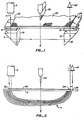
- Figure 1 is a diagrammatic side view of the apparatus of the invention; and
- Figure 2 is a diagrammatic side view of an alternative embodiment of the apparatus of the invention illustrating the projected image of one edge of the fabric workpiece, when the workpiece is not aligned witht he edge of the support surface.
- The apparatus of the invention is illustrated in Figure 1. When in operation, a piece of
fabric 20 is introduced to the apparatus on a transparent transport surface 3. Theleft edge 22 of thefabric 20, as viewed in Figure 1, is positioned on support surface 3 such that, when light rays 7 from light source 5 (which may be capable of emitting light in the visible and/or nonvisible ranges) are directed toward surface 3 andfabric edge 22, an image ofedge 22 is focused on to reflective surface 11 by lens 9. Ideally, lens 9 and reflective surface 11 are positioned with respect to each other and with respect to light source 5 such that the light being directed by lens 9 onto surface 11 strikes surface 11 at a 45° angle of incidence. The image offabric edge 22 is formed at the focal center of reflective surface 11. - The image on reflective surface 11 is again reflected onto a second
reflective surface 15 which is perpendicular to surface 11. This reflected image is then focused by alens 19 to be viewable, by anoperator 40, looking down through the support surface 3. The operator next manually aligns the workpiece laterally until the image offabric edge 22 can be observed by anobserver 40, or other reading device such as a photocell or charge coupled device (CCD) camera. - Once the image of
fabric edge 22 can be observed at the right edge of transport surface 3, an attempt is made to align the image offabric edge 22 with theactual fabric edge 24 so tht the image offabric edge 22 andfabric edge 24 will be coincidental. When this has occurred, thefabric 20 will have been centered with respect to the transport surface's edges such that a further operation (such as folding bydevice 30 or stitching, etc.) may be performed onfabric 20. - Lens 9 is ideally a fully transparent lens to enable sufficient light from source 5 to be directed onto reflective surface 11 to form an image of
edge 22. On the other hand,lens 19 is ideally a frosted or partially transparent lens to enable the image reflected from surface 11 ontosurface 15 to be directed in one direction bylens 19 but so as not to allow an image ofedge 24 to be directed bylenses 19 and 9 andreflective surfaces 15 and 11 back to the underside of surface 3 where it would be reflected, with the result that the superimposed images would cause great confusion of theviewer 40. While a frosted lens is desirable in the position oflens 19 to accomplish the desired goal of this invention, it is to be understood that a transparent lens would clearly be within the spirit and scope of the claims of this invention. - -
Reflective surfaces 11 and 15 are shown as surfaces ofprisms surface 15 and then ontolens 19, but it is to be understood that a single mirrored or other reflective surface is equally suitable in this embodiment and is clearly intended to fall within the spirit and scope of the claims of this invention. - Similarly, as shown in Figure 2, the lens and mirrored prism periscope arrangement depicted in Figure 1 for conveying the image of
edge 22 to beneath the transparent surface 3 on the opposite side of the workpiece can be accomplished by other suitable means such as a fiber-optic bundle 42. Figure 2 illustrates generally the same apparatus of Figure 1 and like parts of the apparatus are referred to by the same reference numeral but with a subscript. Figure 2 also illustrates what happens when thefabric piece 20 is not correctly positioned on transport surface 3. The same procedure is followed whether the apparatus of Figure 1 or Figure 2 is utilized. - Light from source 5 is transmitted through surface 3 and the image of
edge 22 is directed by a bundle ofoptic fibers 42 to form an image offabric edge 22 beneath the left edge of surface 3. Thefabric piece 20 must then be manipulated, either manually or by a guide wheel, laterally over transport surface 3, as indicated by the arrow 25, until the image offabric edge 22 appears to the observer atposition 40 to be aligned with theactual fabric edge 24. When this happens, thefabric piece 20 has been centered with respect to the edges of the transport surface 3 such that an operation bedevice 30 can be performed onfabric 20. - In the above described embodiments, the edge image conveying means (i.e. the periscope arrangement of
lenses 9 and 19 and theprisms sensor 40 are described as being above the work surface 3, with the edge image conveying means being below the surface 3, it should be understood that these positions are relative and could be reversed so that the light source 5 and viewer orsensor 40 are below the surface 3 and the edge image conveying means is above the surface 3.
Claims (4)
Applications Claiming Priority (2)
| Application Number | Priority Date | Filing Date | Title |
|---|---|---|---|
| US761064 | 1985-07-31 | ||
| US06/761,064 US4655596A (en) | 1983-10-28 | 1985-07-31 | Workpiece centering apparatus and method |
Publications (3)
| Publication Number | Publication Date |
|---|---|
| EP0213265A2 EP0213265A2 (en) | 1987-03-11 |
| EP0213265A3 EP0213265A3 (en) | 1988-01-07 |
| EP0213265B1 true EP0213265B1 (en) | 1990-11-28 |
Family
ID=25061009
Family Applications (1)
| Application Number | Title | Priority Date | Filing Date |
|---|---|---|---|
| EP86103306A Expired EP0213265B1 (en) | 1985-07-31 | 1986-03-12 | Workpiece centering apparatus and method |
Country Status (4)
| Country | Link |
|---|---|
| US (1) | US4655596A (en) |
| EP (1) | EP0213265B1 (en) |
| JP (1) | JPH06104152B2 (en) |
| DE (1) | DE3675847D1 (en) |
Families Citing this family (5)
| Publication number | Priority date | Publication date | Assignee | Title |
|---|---|---|---|---|
| DK134291D0 (en) * | 1991-07-12 | 1991-07-12 | Tim Newlin | SENSOR FOR OPTICAL DETECTION OF CONSUMER INDICATOR INDICATION OF CONSUMPTION |
| RU2360584C1 (en) * | 2008-01-09 | 2009-07-10 | Государственное образовательное учреждение высшего профессионального образования "Орловский государственный технический университет" (ОрелГТУ) | Device for accuracy control of pattern cutting of sewing details in pack |
| US10290118B2 (en) * | 2015-08-06 | 2019-05-14 | Cognex Corporation | System and method for tying together machine vision coordinate spaces in a guided assembly environment |
| CN108188793A (en) * | 2018-01-16 | 2018-06-22 | 湖南凯斯机械股份有限公司 | Baseplate of sewing machine processing unit (plant) |
| US10393510B1 (en) | 2018-11-28 | 2019-08-27 | Innovatech, Llc | Measuring apparatus and method for measuring flexible elongated parts |
Family Cites Families (4)
| Publication number | Priority date | Publication date | Assignee | Title |
|---|---|---|---|---|
| US3548196A (en) * | 1968-06-05 | 1970-12-15 | Ivanhoe Research Corp | Method and apparatus for automatically centering fabric workpieces regardless of their size within the operating range |
| GB1253994A (en) * | 1968-08-01 | 1971-11-17 | British Iron Steel Research | Apparatus for detecting and/or measuring the width of strip material |
| US3688804A (en) * | 1970-02-02 | 1972-09-05 | Fife Corp | Method for web guiding of carpet material |
| IT1083519B (en) * | 1977-06-15 | 1985-05-21 | Bassani Mariano | ROPE FABRIC OPENING SYSTEM |
-
1985
- 1985-07-31 US US06/761,064 patent/US4655596A/en not_active Expired - Lifetime
-
1986
- 1986-02-28 JP JP61042051A patent/JPH06104152B2/en not_active Expired - Lifetime
- 1986-03-12 EP EP86103306A patent/EP0213265B1/en not_active Expired
- 1986-03-12 DE DE8686103306T patent/DE3675847D1/en not_active Expired - Lifetime
Also Published As
| Publication number | Publication date |
|---|---|
| JPS6232997A (en) | 1987-02-12 |
| US4655596A (en) | 1987-04-07 |
| EP0213265A2 (en) | 1987-03-11 |
| DE3675847D1 (en) | 1991-01-10 |
| EP0213265A3 (en) | 1988-01-07 |
| JPH06104152B2 (en) | 1994-12-21 |
Similar Documents
| Publication | Publication Date | Title |
|---|---|---|
| US4249294A (en) | Optical pulley alignment tool | |
| US20020153477A1 (en) | Work piece feeding machine and abrasive system | |
| US4655596A (en) | Workpiece centering apparatus and method | |
| CN100520381C (en) | Polarizing film detection apparatus and method | |
| CN211148402U (en) | Shading glue size and appearance double-station detection machine | |
| US6902468B2 (en) | Assembly for machining the edges of spectacle lenses | |
| US7538892B2 (en) | Method and apparatus for examining end faces of light guides | |
| US2889941A (en) | Arrangement to inspect stacked legendized papers, in particular to read the addresses of stacked letters | |
| KR100458613B1 (en) | Method and system for fabricating a liquid crystal display by optically detecting anisotropic angular misalignment | |
| US5201145A (en) | Monocrystal ingot attitude-adjusting/surface-grinding/conveying apparatus | |
| US5506928A (en) | Optical fiber gripping and positioning apparatus | |
| CN100587553C (en) | Automatic jig installation device for spectacle lens and automatic jig installation method | |
| EP0179183B1 (en) | Optical fiber characteristic measuring method and apparatus | |
| US4088409A (en) | Optical roll alignment device | |
| EP0174428A2 (en) | Apparatus for fusion splicing optical fibers | |
| ITPR20010040A1 (en) | PROCEDURE AND APPARATUS TO INSPECT CONTAINERS. | |
| JP2007268706A (en) | Layout block device for lens | |
| JP2005306413A (en) | Method and device for placing sheet-like element, and method and device for manufacturing sheet-like optical element package using the same | |
| US20110096978A1 (en) | Off-Axis Sheet-Handling Apparatus and Technique for Transmission-Mode Measurements | |
| JPH11167165A (en) | Method for aligning frame detection part of microfilm retrieving device and microfilm for alignment | |
| CN221063600U (en) | An optical glass lens detection and placement machine | |
| JP4181563B2 (en) | Lens holder and method for processing eyeglass lens using the holder | |
| US3652147A (en) | Paper cutting machines | |
| JP2698595B2 (en) | Component positioning device and component assembly device | |
| CA2149383C (en) | Optical fiber gripping and positioning apparatus |
Legal Events
| Date | Code | Title | Description |
|---|---|---|---|
| PUAI | Public reference made under article 153(3) epc to a published international application that has entered the european phase |
Free format text: ORIGINAL CODE: 0009012 |
|
| 17P | Request for examination filed |
Effective date: 19860312 |
|
| AK | Designated contracting states |
Kind code of ref document: A2 Designated state(s): DE GB IT |
|
| PUAL | Search report despatched |
Free format text: ORIGINAL CODE: 0009013 |
|
| AK | Designated contracting states |
Kind code of ref document: A3 Designated state(s): DE GB IT |
|
| RHK1 | Main classification (correction) |
Ipc: D06H 3/08 |
|
| 17Q | First examination report despatched |
Effective date: 19890802 |
|
| GRAA | (expected) grant |
Free format text: ORIGINAL CODE: 0009210 |
|
| AK | Designated contracting states |
Kind code of ref document: B1 Designated state(s): DE GB IT |
|
| REF | Corresponds to: |
Ref document number: 3675847 Country of ref document: DE Date of ref document: 19910110 |
|
| ITF | It: translation for a ep patent filed | ||
| ITTA | It: last paid annual fee | ||
| PLBE | No opposition filed within time limit |
Free format text: ORIGINAL CODE: 0009261 |
|
| STAA | Information on the status of an ep patent application or granted ep patent |
Free format text: STATUS: NO OPPOSITION FILED WITHIN TIME LIMIT |
|
| 26N | No opposition filed | ||
| PG25 | Lapsed in a contracting state [announced via postgrant information from national office to epo] |
Ref country code: DE Effective date: 19920101 |
|
| PGFP | Annual fee paid to national office [announced via postgrant information from national office to epo] |
Ref country code: GB Payment date: 20010307 Year of fee payment: 16 |
|
| REG | Reference to a national code |
Ref country code: GB Ref legal event code: 732E |
|
| REG | Reference to a national code |
Ref country code: GB Ref legal event code: IF02 |
|
| PG25 | Lapsed in a contracting state [announced via postgrant information from national office to epo] |
Ref country code: GB Free format text: LAPSE BECAUSE OF NON-PAYMENT OF DUE FEES Effective date: 20020312 |
|
| GBPC | Gb: european patent ceased through non-payment of renewal fee |
Effective date: 20020312 |
|
| PG25 | Lapsed in a contracting state [announced via postgrant information from national office to epo] |
Ref country code: IT Free format text: LAPSE BECAUSE OF NON-PAYMENT OF DUE FEES;WARNING: LAPSES OF ITALIAN PATENTS WITH EFFECTIVE DATE BEFORE 2007 MAY HAVE OCCURRED AT ANY TIME BEFORE 2007. THE CORRECT EFFECTIVE DATE MAY BE DIFFERENT FROM THE ONE RECORDED. Effective date: 20050312 |