EP0213121B1 - Fastener wrenching means - Google Patents
Fastener wrenching means Download PDFInfo
- Publication number
- EP0213121B1 EP0213121B1 EP85901269A EP85901269A EP0213121B1 EP 0213121 B1 EP0213121 B1 EP 0213121B1 EP 85901269 A EP85901269 A EP 85901269A EP 85901269 A EP85901269 A EP 85901269A EP 0213121 B1 EP0213121 B1 EP 0213121B1
- Authority
- EP
- European Patent Office
- Prior art keywords
- tool
- bore
- key
- holder member
- key member
- Prior art date
- Legal status (The legal status is an assumption and is not a legal conclusion. Google has not performed a legal analysis and makes no representation as to the accuracy of the status listed.)
- Expired
Links
Images

Classifications
-
- B—PERFORMING OPERATIONS; TRANSPORTING
- B25—HAND TOOLS; PORTABLE POWER-DRIVEN TOOLS; MANIPULATORS
- B25B—TOOLS OR BENCH DEVICES NOT OTHERWISE PROVIDED FOR, FOR FASTENING, CONNECTING, DISENGAGING, OR HOLDING
- B25B23/00—Details of, or accessories for, spanners, wrenches, screwdrivers
- B25B23/14—Arrangement of torque limiters or torque indicators in wrenches or screwdrivers
- B25B23/1415—Break members; Arrangements specially adapted for break-bolts
-
- B—PERFORMING OPERATIONS; TRANSPORTING
- B25—HAND TOOLS; PORTABLE POWER-DRIVEN TOOLS; MANIPULATORS
- B25B—TOOLS OR BENCH DEVICES NOT OTHERWISE PROVIDED FOR, FOR FASTENING, CONNECTING, DISENGAGING, OR HOLDING
- B25B21/00—Portable power-driven screw or nut setting or loosening tools; Attachments for drilling apparatus serving the same purpose
- B25B21/001—Combined nut setting and crimping
Definitions
- This invention relates to a power assisted wrenching tool, and in particular, to a wrenching tool for attachment of fasteners in loose and interference fit applications.
- Threaded fasteners are frequently used in loose fit applications in which it is difficult to work from both sides of the workpiece. This occurs quite frequently in the aerospace industry, and a particular fastening system has been developed in this industry.
- This system employs frangible fasteners comprising a bolt with a threaded nut member having a threaded collar and a distal wrenching ring separated by a notched section that provides a predetermined limiting torque which when exceeded permits the wrenching ring to shear from the threaded collar leaving the latter in place at a precise predetermined tensile loading on the bolt member.
- the threaded collar has an upset portion, usually a slightly elliptical shape, to provide a frictional spring lock to prevent the fastener from spinning off in the event that the residual tension on the fastener is lost.
- these fasteners are used both in loose and interference fit applications, and in the former applications it has been the practice to use a drive tool having a center key which is inserted into a broached keyway of the bolt to hold the bolt stationary while the threaded collar is applied.
- the key is mounted in a keyway broached in the center core of a key holder member of the wrenching tool.
- the holder member is slidably received in a central through bore of the driven, socket member.
- the key is fixedly secured in the core of the holder member usually by a set screw.
- U.S. Patent 3,584,527 is typical of these tools.
- the key is inserted from the rear of the tool, and a retainer ring secures the key.
- the prior key retainers in these tools are cumbersome and cause delays and difficulties in changing the tools from the application of fasteners in interference fit and loose fit applications, since in only the latter is the key necessary.
- the key often breaks during use and it is necessary to replace broken and worn keys, again a time consuming operation with the customary key retainers. Occasionally, the key becomes jammed in a bolt during the application of a threaded fastener and, when this occurs, the tool is immobilized and difficulties are removing the tool from the work.
- the wrenching tool includes a motor assembly 10 with a motor housing 12 and an integral, dependent hand grip 14 having a trigger 16.
- the motor assembly 10 is supplied with a motive fluid, commonly compressed air, through a flexible hose 18.
- the particularly illustrated wrenching tool includes a torque control assembly 20 which is threadably engaged on the threaded boss 22 of the housing 12 and which has an internal shaft, not shown, that is connected to the motor drive shaft.
- the torque control assembly 20 contains an internal friction clutch which is preloaded to a predetermined torque and this assembly is commonly used with the non-frangible fasteners to provide a control on the tightening torque applied to the fasteners. It is not needed when the tool is to be used with frangible fasteners.
- the torque control assembly is attached to the tool head assembly 23.
- This head assembly has a housing 24 which contains a plurality of gears that provide a gear train with the appropriate speed reduction characteristic for the particular tool.
- the head assembly 23 supports a socket assembly 24.
- a number of interchangeable socket assemblies can be used to provide a variable extension from the face 28 of the head assembly housing 24.
- the particular socket assembly illustrated is flush with this plate and receives in its socket 30, the wrenching ring 32 of a frangible fastener 34.
- the socket assembly is also illustrated with the key 36 of the invention restrained in the core of the holder member 38.
- the workpiece is generally indicated at 40 and comprises two members to be retained by a bolt fastener 42 and a threaded collar fastener 44 of the frangible fastener unit.
- the socket assembly 26 removed from the head assembly 23.
- the socket assembly comprises three major parts.
- the key 36 has one or more flats 46 and is received within a broached keyway concentric in the core 48 of the holder member 38.
- the holder member 38 is slidably received within a through bore of the outer, driven member 50 which has a plurality of sprocket gear teeth 52 about its periphery. These gear teeth 52 engage with gears within the head assembly 23.
- the forward end of the driven member 50 has a socket 30 for receiving the wrenching ring 32 previously mentioned with regard to Figure 1.
- the holder member 38 has a transverse bore 54 which receives a spring retainer that restrains this member against rotation while permitting its relative axial displacement within the driven member 50.
- key 36 has flats 46 coextensive its length with one end chamfered at 56 and with a peripheral groove 58 adjacent the chamfered end.
- the aforementioned sprocket gear teeth 52 preferably are integral with the driven member 50 and this member has a socket end 30 which is in communication with a through bore, not shown, having a sufficient inside diameter to slideably receive the central core 48 of the holder member 38.
- the holder member 38 has a center bore 60 which is broached to provide flated surfaces which mate the flatted surfaces 46 of key 36.
- the holder member has a cross bore 62 which intersects the longitudinal center bore 60. This cross bore 62 is of sufficient diameter to receive the ball 64 which serves as a detent, cooperatively engaging the peripheral groove 58 of the key 36.
- the workpiece 40 comprises plates 41 and 43 which are to be fastened and, for this purpose, have aligned bores which receive the shank of a bolt 42.
- Bolt 42 is used in combination with a frangible fastener 34 having an internally threaded collar 44 on one end, and a wrenching ring 32 on its opposite end, separated by an annular notched section 45 which has a groove 47 of a predetermined depth to provide a predetermined breakaway torque for separating the wrenching ring from the collar 44.
- the head assembly 22 of the wrenching tool of the invention is shown with the key 36 of the invention retained in the holder member 38 which is restrained against rotation by spring 66.
- the fastener 34 is shown applied on bolt 42, in a conventional loose fit.
- the bolt 42 has a center keyway 68 with mating flats to receive the end of key 36 and the wrenching collar 32 is placed in the socket 30 of the wrenching tool.
- the work is to be secured by actuation of the wrenching tool which advances the collar 44 on the bolt 42.
- This operation is illustrated in Figure 6 where the locking collar 44 is advanced on bolt 42 with the bolt 42 drawn into tension, restraining plates 41 and 43.
- the holder member 38 is slideably displaced in the wrenching tool, reaching the position shown in Figure 6.
- the holder member 38 is retained stationary by the spring 66 which has a bent end received in the through bore 54 in the end of the holder member 38.
- the continued application of torque to the frangible fastener 34 results in failure of its notched center section and separation of the wrenching collar 32 from the fastener collar 44 which remains in place, securely locking the fastener.
- the spring 66 returns the holder member 38 to its normal position, ejecting the wrenching ring 32 from the internal socket 30 of the wrenching tool.
- the device will also work with non-frangible fastener systems which do not release a separate wrenching collar to the tool.
- the wrenching tool and fastener system is shown in greater detail.
- the bolt 42 is shown in a loose fit extending through plates 41 and 43 and with its threaded end entering into the internally threaded fastener collar 44.
- the wrenching ring 32 at the opposite end of the frangible fastener 34 is shown engaged in the socket 30 of the driven member 50.
- the holder unit 38 is shown in its fully extended position and the key 36 is shown restrained by the ball 64 that is received in the cross bore 62 and projects into the central bore 60 of the holder member 38.
- ball 64 is captured in cross bore 62 by staked means such as a distal annular lip 65 on the inside wall of cross bore 62.
- the key 36 is secured by ball 64 which seats in the peripheral groove 58 of the key.
- the ball 64 is held in this position by the driven member 50, surrounding the holder member 38.
- the driven member 50 is illustrated with its sprocket gear teeth 52 meshed with the drive teeth of a driving sprocket gear 70 contained within the housing 24 of the head assembly 23.
- the holder member 38 is restrained against rotation in this assembly by the end of spring 66 which extends into the cross bore 64, all as previously described.
- Figure 9 illustrates the wrenching tool immediately upon separation of the frangible wrenching ring 32 from the fastener collar 44. This occurs when the fastening collar is advanced sufficiently on bolt 42 to achieve a predetermined tension in bolt 42, compressing the workpiece 40.
- the wrenching tool is retracted from the work, extracting the key 36 from the broached keyway 68 in the end of bolt 42.
- spring 66 resiliently biases the holder member 38 towards its extended position, advancing this unit until the shoulder 72 abuts the wrenching ring 32 and ejects this ring from the socket.
- the key 36 can be readily extracted from the socket assembly 26 in the manner shown in Figure 10.
- the annular groove 74 is positioned in exact alignment with the cross bore 62 of the holder member 38, permitting ball 64 to move laterally, retracting the ball from its engagement with groove 58 in the end of the key 36. This frees key 36 for extraction from the assembly, as shown in Figure 6.
- shoulder 63 is visible in through bore 60 which provides an abutment stop for key 36.
- the annular groove 74 can be aligned with cross bore 62, and the bias of spring 66 can be released from holder 38 in the aligned position by placing a spacer block 75 between the back of housing 24 of the head assembly and the head 76 of the holder member 38.
- the spacer block can be permanently attached to the tool by a pivotal attachment to permit it to be swung into the illustrated position when needed and moved to one side when the tool is in use.
- the key 36 can be set in the socket assembly in its restrained position within holder 38 by forcefully advancing the key 36 in the manner illustrated in Figure 11.
- the ball 64 is in its inwardly displaced position, restrained therein by the driven member 50.
- the inboard end of key 36 encounters the ball and its inward movement is interfered by the ball.
- the key has adequate resiliency to flex sufficiently to permit its head end to advance past the ball 64.
- the head end of key 36 is chamfered as shown at 56 at an angle of 10 to about 65 degrees, preferably 45 degrees, with its longitudinal axis, and the peripheral groove 58 is located within a distance from 0.2 to about 0.5 times the diameter of ball 64. Additional, there should be a slight tolerance in the fit between the key and its receiving bore 60. Since this provides a facile and fast manner for seating the key 36 in the socket assembly, it constitutes a preferred embodiment of the key 36 for use in the invention.
- the bore 60 in the center of the holder 38 is preferably coextensive the length of the holder member 38 thereby permitting access through the head 76 of holder member 38 thereby permitting one to insert a pin to forcefully eject key 36 should the latter become jammed in the holder member 38.
- an angular cross bore 80 can be provided in this holder member 38, intersecting the central bore 60 in the manner illustrated in Figure 12.
- the invention as thus described provides a number of advantages over the conventionally employed unit having a key which is retained in the holder member by set screws and the like.
- the key can be very quickly inserted or extracted from the holder member without requiring its disassembly or removal of a set screw. This is important particularly when switching the tool between interference and loose fit applications, as is frequently required.
- a broken key segment within the holder 38 can be readily removed by the alignment of the annular groove 74 with the cross bore 62 in the holder 38 which permits the ball 64 to release the key and the key will then fall from the holder 38.
- a pin can be advanced through the continuous through bore 60 from the head end 38 of the assembly.
- a frequent occurrence is the jamming of the key 36 in the broached keyway 68 of the fastener 42.
- the entire wrenching tool is captured and retained until the key 36 can be freed or broken to permit removal of the wrenching tool.
- the wrenching tool can be readily freed from the fastener system by simply moving the holder member 38 into the key disengagement position and, if necessary, using a spacer block such as 75 for this purpose. Once the tool is aligned in this manner, it can readily be removed, leaving the jammed key 36 in the bolt 42 for subsequent extraction.
Landscapes
- Engineering & Computer Science (AREA)
- Mechanical Engineering (AREA)
- Details Of Spanners, Wrenches, And Screw Drivers And Accessories (AREA)
- Drilling Tools (AREA)
Abstract
Description
- This invention relates to a power assisted wrenching tool, and in particular, to a wrenching tool for attachment of fasteners in loose and interference fit applications.
- Threaded fasteners are frequently used in loose fit applications in which it is difficult to work from both sides of the workpiece. This occurs quite frequently in the aerospace industry, and a particular fastening system has been developed in this industry. This system employs frangible fasteners comprising a bolt with a threaded nut member having a threaded collar and a distal wrenching ring separated by a notched section that provides a predetermined limiting torque which when exceeded permits the wrenching ring to shear from the threaded collar leaving the latter in place at a precise predetermined tensile loading on the bolt member. Often the threaded collar has an upset portion, usually a slightly elliptical shape, to provide a frictional spring lock to prevent the fastener from spinning off in the event that the residual tension on the fastener is lost. Typically, these fasteners are used both in loose and interference fit applications, and in the former applications it has been the practice to use a drive tool having a center key which is inserted into a broached keyway of the bolt to hold the bolt stationary while the threaded collar is applied.
- Typically the key is mounted in a keyway broached in the center core of a key holder member of the wrenching tool. The holder member is slidably received in a central through bore of the driven, socket member. The key is fixedly secured in the core of the holder member usually by a set screw. U.S. Patent 3,584,527 is typical of these tools. In this patent, the key is inserted from the rear of the tool, and a retainer ring secures the key. The prior key retainers in these tools are cumbersome and cause delays and difficulties in changing the tools from the application of fasteners in interference fit and loose fit applications, since in only the latter is the key necessary. Also the key often breaks during use and it is necessary to replace broken and worn keys, again a time consuming operation with the customary key retainers. Occasionally, the key becomes jammed in a bolt during the application of a threaded fastener and, when this occurs, the tool is immobilized and difficulties are removing the tool from the work.
- Bits have been retained in tools with detent balls which seat in grooves about the inserted end of the bits. An example of such detent ball retainers is German Patent 1,161,817 in which a screw driver blade is retained in a holder of a power driven tool with a detent ball.
- The invention is defined in claim 1. Brief description of the drawings
- Embodiments of the invention are shown in the following Figures:
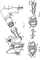
- Figure 1 is an exploded perspective view of the wrenching tool;
- Figure 2 is a perspective view of the socket subassembly of the wrenching tool;
- Figure 3 is an exploded perspective view of the socket drive subassembly;
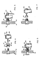
- Figure 4 is an elevational sectional view of a fastener system and the wrenching tool;
- Figure 5 is an elevational sectional view illustrating the application of the nut to the bolt of the fastener system;
- Figure 6 is an elevational sectional view illustrating the torquing of the fastener system;
- Figure 7 is an elevational sectional view illustrating the separation of the wrenching collar and the wrenching tool;
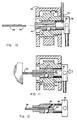
- Figure 8 is an enlarged sectional view of Figure 5;
- Figure 9 is an elevational sectional view illustrating the tool and wrenching collar separated from the fastener system;
- Figure 10 illustrates the retraction of a key from the wrenching tool of the invention;
- Figure 11 is an elevational view illustrating insertion of the key into the tool; and
- Figure 12 illustrates an alternative construction of the key holder member of the invention.
- Referring now to Figure 1, the invention is shown as employed in an otherwise conventional wrenching tool. The wrenching tool includes a
motor assembly 10 with amotor housing 12 and an integral,dependent hand grip 14 having atrigger 16. Themotor assembly 10 is supplied with a motive fluid, commonly compressed air, through aflexible hose 18. The particularly illustrated wrenching tool includes atorque control assembly 20 which is threadably engaged on the threadedboss 22 of thehousing 12 and which has an internal shaft, not shown, that is connected to the motor drive shaft. Thetorque control assembly 20 contains an internal friction clutch which is preloaded to a predetermined torque and this assembly is commonly used with the non-frangible fasteners to provide a control on the tightening torque applied to the fasteners. It is not needed when the tool is to be used with frangible fasteners. - The torque control assembly is attached to the
tool head assembly 23. This head assembly has ahousing 24 which contains a plurality of gears that provide a gear train with the appropriate speed reduction characteristic for the particular tool. At its upper end, thehead assembly 23 supports asocket assembly 24. A number of interchangeable socket assemblies can be used to provide a variable extension from theface 28 of thehead assembly housing 24. The particular socket assembly illustrated is flush with this plate and receives in itssocket 30, thewrenching ring 32 of afrangible fastener 34. The socket assembly is also illustrated with thekey 36 of the invention restrained in the core of theholder member 38. The workpiece is generally indicated at 40 and comprises two members to be retained by abolt fastener 42 and a threadedcollar fastener 44 of the frangible fastener unit. - Referring now to Figure 2, there is illustrated the
socket assembly 26 removed from thehead assembly 23. The socket assembly comprises three major parts. The key 36 has one ormore flats 46 and is received within a broached keyway concentric in thecore 48 of theholder member 38. Theholder member 38 is slidably received within a through bore of the outer, drivenmember 50 which has a plurality ofsprocket gear teeth 52 about its periphery. Thesegear teeth 52 engage with gears within thehead assembly 23. The forward end of the drivenmember 50 has asocket 30 for receiving thewrenching ring 32 previously mentioned with regard to Figure 1. Theholder member 38 has atransverse bore 54 which receives a spring retainer that restrains this member against rotation while permitting its relative axial displacement within the drivenmember 50. - Referring now to Figure 3, the socket assembly is shown in exploded view. As there illustrated,
key 36 hasflats 46 coextensive its length with one end chamfered at 56 and with aperipheral groove 58 adjacent the chamfered end. The aforementionedsprocket gear teeth 52 preferably are integral with the drivenmember 50 and this member has asocket end 30 which is in communication with a through bore, not shown, having a sufficient inside diameter to slideably receive thecentral core 48 of theholder member 38. Theholder member 38 has acenter bore 60 which is broached to provide flated surfaces which mate theflatted surfaces 46 ofkey 36. Intermediate its length, the holder member has across bore 62 which intersects thelongitudinal center bore 60. Thiscross bore 62 is of sufficient diameter to receive theball 64 which serves as a detent, cooperatively engaging theperipheral groove 58 of thekey 36. - Referring now to Figures 4-7, the use of the invention will be briefly described. As shown in Figure 4, the
workpiece 40 comprisesplates bolt 42.Bolt 42 is used in combination with afrangible fastener 34 having an internally threadedcollar 44 on one end, and awrenching ring 32 on its opposite end, separated by an annular notchedsection 45 which has agroove 47 of a predetermined depth to provide a predetermined breakaway torque for separating the wrenching ring from thecollar 44. Thehead assembly 22 of the wrenching tool of the invention is shown with thekey 36 of the invention retained in theholder member 38 which is restrained against rotation byspring 66. - Referring to Figure 5, the
fastener 34 is shown applied onbolt 42, in a conventional loose fit. Thebolt 42 has acenter keyway 68 with mating flats to receive the end ofkey 36 and the wrenchingcollar 32 is placed in thesocket 30 of the wrenching tool. In this position, the work is to be secured by actuation of the wrenching tool which advances thecollar 44 on thebolt 42. This operation is illustrated in Figure 6 where the lockingcollar 44 is advanced onbolt 42 with thebolt 42 drawn into tension, restrainingplates collar 44 is advanced onbolt 42, theholder member 38 is slideably displaced in the wrenching tool, reaching the position shown in Figure 6. Throughout this movement, theholder member 38 is retained stationary by thespring 66 which has a bent end received in the throughbore 54 in the end of theholder member 38. The continued application of torque to thefrangible fastener 34 results in failure of its notched center section and separation of the wrenchingcollar 32 from thefastener collar 44 which remains in place, securely locking the fastener. When the wrenching tool is retracted in the manner shown in Figure 7, thespring 66 returns theholder member 38 to its normal position, ejecting thewrenching ring 32 from theinternal socket 30 of the wrenching tool. The device will also work with non-frangible fastener systems which do not release a separate wrenching collar to the tool. - Referring now to Figure 8, the wrenching tool and fastener system is shown in greater detail. As there illustrated, the
bolt 42 is shown in a loose fit extending throughplates fastener collar 44. Thewrenching ring 32 at the opposite end of thefrangible fastener 34 is shown engaged in thesocket 30 of the drivenmember 50. Theholder unit 38 is shown in its fully extended position and the key 36 is shown restrained by theball 64 that is received in the cross bore 62 and projects into thecentral bore 60 of theholder member 38. Preferably,ball 64 is captured in cross bore 62 by staked means such as a distalannular lip 65 on the inside wall ofcross bore 62. The key 36 is secured byball 64 which seats in theperipheral groove 58 of the key. Theball 64 is held in this position by the drivenmember 50, surrounding theholder member 38. The drivenmember 50 is illustrated with itssprocket gear teeth 52 meshed with the drive teeth of a drivingsprocket gear 70 contained within thehousing 24 of thehead assembly 23. Theholder member 38 is restrained against rotation in this assembly by the end ofspring 66 which extends into the cross bore 64, all as previously described. - Figure 9 illustrates the wrenching tool immediately upon separation of the
frangible wrenching ring 32 from thefastener collar 44. This occurs when the fastening collar is advanced sufficiently onbolt 42 to achieve a predetermined tension inbolt 42, compressing theworkpiece 40. The wrenching tool is retracted from the work, extracting the key 36 from the broachedkeyway 68 in the end ofbolt 42. As the wrenching tool is retracted,spring 66 resiliently biases theholder member 38 towards its extended position, advancing this unit until theshoulder 72 abuts thewrenching ring 32 and ejects this ring from the socket. - As the
holder member 38 moves to advance theball 64 past the alignment with theannular groove 74 in the drivenmember 50, theball 64 remains in its detenting position, securing the key 36 as this alignment is only a transient condition and insufficient time is provided forball 64 to retract from its illustrated position engaging thegroove 58 ofkey 36. - The key 36 can be readily extracted from the
socket assembly 26 in the manner shown in Figure 10. As there illustrated, theannular groove 74 is positioned in exact alignment with the cross bore 62 of theholder member 38, permittingball 64 to move laterally, retracting the ball from its engagement withgroove 58 in the end of the key 36. This frees key 36 for extraction from the assembly, as shown in Figure 6. With the key removed,shoulder 63 is visible in throughbore 60 which provides an abutment stop forkey 36. Theannular groove 74 can be aligned withcross bore 62, and the bias ofspring 66 can be released fromholder 38 in the aligned position by placing aspacer block 75 between the back ofhousing 24 of the head assembly and thehead 76 of theholder member 38. If desired, the spacer block can be permanently attached to the tool by a pivotal attachment to permit it to be swung into the illustrated position when needed and moved to one side when the tool is in use. - One feature of the invention is that the key 36 can be set in the socket assembly in its restrained position within
holder 38 by forcefully advancing the key 36 in the manner illustrated in Figure 11. In this application, theball 64 is in its inwardly displaced position, restrained therein by the drivenmember 50. The inboard end of key 36 encounters the ball and its inward movement is interfered by the ball. The key, however, has adequate resiliency to flex sufficiently to permit its head end to advance past theball 64. For this purpose, the head end ofkey 36 is chamfered as shown at 56 at an angle of 10 to about 65 degrees, preferably 45 degrees, with its longitudinal axis, and theperipheral groove 58 is located within a distance from 0.2 to about 0.5 times the diameter ofball 64. Additional, there should be a slight tolerance in the fit between the key and its receiving bore 60. Since this provides a facile and fast manner for seating the key 36 in the socket assembly, it constitutes a preferred embodiment of the key 36 for use in the invention. - The
bore 60 in the center of theholder 38 is preferably coextensive the length of theholder member 38 thereby permitting access through thehead 76 ofholder member 38 thereby permitting one to insert a pin to forcefully eject key 36 should the latter become jammed in theholder member 38. Alternatively, an angular cross bore 80 can be provided in thisholder member 38, intersecting thecentral bore 60 in the manner illustrated in Figure 12. - The invention as thus described provides a number of advantages over the conventionally employed unit having a key which is retained in the holder member by set screws and the like. Firstly, the key can be very quickly inserted or extracted from the holder member without requiring its disassembly or removal of a set screw. This is important particularly when switching the tool between interference and loose fit applications, as is frequently required. A broken key segment within the
holder 38 can be readily removed by the alignment of theannular groove 74 with the cross bore 62 in theholder 38 which permits theball 64 to release the key and the key will then fall from theholder 38. In the event that the key is jammed in this holder, a pin can be advanced through the continuous through bore 60 from thehead end 38 of the assembly. Also, a frequent occurrence is the jamming of the key 36 in the broachedkeyway 68 of thefastener 42. When this has occurred in the past, the entire wrenching tool is captured and retained until the key 36 can be freed or broken to permit removal of the wrenching tool. With the key and detent ball of this invention the wrenching tool can be readily freed from the fastener system by simply moving theholder member 38 into the key disengagement position and, if necessary, using a spacer block such as 75 for this purpose. Once the tool is aligned in this manner, it can readily be removed, leaving the jammed key 36 in thebolt 42 for subsequent extraction.
Claims (11)
whereby said key member (36) is axially restrained in said holder member (38) when said detent ball (64) is seated in said peripheral groove (58) of said key member (36) and can be released therefrom by aligning the cross bore (62) with the annular groove (74), whereby the detent ball (64) is freed for laterally outward displacement.
Priority Applications (1)
| Application Number | Priority Date | Filing Date | Title |
|---|---|---|---|
| AT85901269T ATE52212T1 (en) | 1985-02-19 | 1985-02-19 | WRENCH. |
Applications Claiming Priority (1)
| Application Number | Priority Date | Filing Date | Title |
|---|---|---|---|
| PCT/US1985/000296 WO1986004853A1 (en) | 1985-02-19 | 1985-02-19 | Fastener wrenching means |
Publications (3)
| Publication Number | Publication Date |
|---|---|
| EP0213121A1 EP0213121A1 (en) | 1987-03-11 |
| EP0213121A4 EP0213121A4 (en) | 1988-03-23 |
| EP0213121B1 true EP0213121B1 (en) | 1990-04-25 |
Family
ID=22188590
Family Applications (1)
| Application Number | Title | Priority Date | Filing Date |
|---|---|---|---|
| EP85901269A Expired EP0213121B1 (en) | 1985-02-19 | 1985-02-19 | Fastener wrenching means |
Country Status (5)
| Country | Link |
|---|---|
| EP (1) | EP0213121B1 (en) |
| JP (1) | JPH0735027B2 (en) |
| AT (1) | ATE52212T1 (en) |
| DE (1) | DE3577287D1 (en) |
| WO (1) | WO1986004853A1 (en) |
Families Citing this family (4)
| Publication number | Priority date | Publication date | Assignee | Title |
|---|---|---|---|---|
| US4617844A (en) * | 1983-07-18 | 1986-10-21 | Vsi Corporation | Removable key for wrenching tool |
| GB2281948B (en) * | 1993-09-15 | 1996-08-14 | Ambrose Dowling | A screw-threaded bolt |
| GB0100393D0 (en) * | 2001-01-06 | 2001-02-14 | B & H Nottingham Ltd | Improvements relating to shearable fasteners |
| FR3061056B1 (en) * | 2016-12-28 | 2019-05-17 | Safran Nacelles | SCREWING TOOL FOR A TOOLING TOOL AND TOOL FOR COMPRISING SUCH A TIP |
Family Cites Families (17)
| Publication number | Priority date | Publication date | Assignee | Title |
|---|---|---|---|---|
| US2239072A (en) * | 1939-03-02 | 1941-04-22 | Dill Mfg Co | Tool |
| US2726091A (en) * | 1953-05-22 | 1955-12-06 | Louis P Topar | Tool holder |
| DE1161817B (en) * | 1955-01-17 | 1964-01-23 | Licentia Gmbh | Power tool, e.g. Electric screwdriver with a device for inserting, loosening and holding insert tools |
| US2762403A (en) * | 1955-03-01 | 1956-09-11 | Gardner Denver Co | Power operated screw setter |
| US2776681A (en) * | 1955-08-15 | 1957-01-08 | Nat Screw & Mfg Company | Power operated tool for use with blind fasteners |
| US2955496A (en) * | 1958-12-15 | 1960-10-11 | Torre Kathryn S La | Power-operated, bolt-holding wrench |
| US3027789A (en) * | 1960-03-24 | 1962-04-03 | Hi Shear Rivet Tool Company | Portable power-driven gear-actuated offset torquing tool |
| US3324747A (en) * | 1965-04-23 | 1967-06-13 | Sweeney Mfg Co B K | Bolt tightening tool |
| US3428327A (en) * | 1966-09-19 | 1969-02-18 | Black & Decker Mfg Co | Quick release rotary tool chuck |
| DE1628079A1 (en) * | 1967-01-31 | 1971-06-09 | Licentia Gmbh | Gearbox suitable for screwing or drilling |
| US3584527A (en) * | 1968-07-29 | 1971-06-15 | Rockwell Mfg Co | Tools and attachments therefor |
| DE2345454A1 (en) * | 1973-09-08 | 1975-03-20 | Bosch Gmbh Robert | TOOL HEAD |
| US4289414A (en) * | 1979-12-06 | 1981-09-15 | Recker Florian B | Torque transmitting coupling |
| US4462281A (en) * | 1982-10-21 | 1984-07-31 | Russell, Burdsall & Ward Corporation | Bolt holding wrench |
| JPS5997850A (en) * | 1982-11-26 | 1984-06-05 | 有限会社 新城製作所 | Attachment of motor rotary tool |
| US4538483A (en) * | 1983-07-18 | 1985-09-03 | V.S.I. Corporation | Fastener wrenching means |
| JPS59187471A (en) * | 1984-03-12 | 1984-10-24 | 室金属工業株式会社 | Holder for bit of electric driver |
-
1985
- 1985-02-19 JP JP60501027A patent/JPH0735027B2/en not_active Expired - Lifetime
- 1985-02-19 EP EP85901269A patent/EP0213121B1/en not_active Expired
- 1985-02-19 WO PCT/US1985/000296 patent/WO1986004853A1/en not_active Ceased
- 1985-02-19 DE DE8585901269T patent/DE3577287D1/en not_active Expired - Lifetime
- 1985-02-19 AT AT85901269T patent/ATE52212T1/en not_active IP Right Cessation
Also Published As
| Publication number | Publication date |
|---|---|
| JPS62501827A (en) | 1987-07-23 |
| EP0213121A4 (en) | 1988-03-23 |
| ATE52212T1 (en) | 1990-05-15 |
| DE3577287D1 (en) | 1990-05-31 |
| EP0213121A1 (en) | 1987-03-11 |
| JPH0735027B2 (en) | 1995-04-19 |
| WO1986004853A1 (en) | 1986-08-28 |
Similar Documents
| Publication | Publication Date | Title |
|---|---|---|
| US4538483A (en) | Fastener wrenching means | |
| EP0193097B1 (en) | Removable key and methods for its use | |
| US4768405A (en) | Locking socket wrench drive device | |
| US6966562B1 (en) | Multiple mode chuck | |
| US8671804B2 (en) | Fastener installation tool with quick change key | |
| US7878094B2 (en) | Tool with extendable handle | |
| EP0043217B1 (en) | Fastener setting tool | |
| US5601387A (en) | Depth adjusting system for a power tool | |
| US5305666A (en) | Installation tool system for Hi-Lok-type fasteners | |
| CA1080007A (en) | Manually operable tool for installing blind anchor nuts | |
| US4862773A (en) | Collet type fastener removal tool | |
| US20050044993A1 (en) | Key and key holder for fastener installation tool | |
| EP3479962B1 (en) | Tooling assembly and method for installation of a frangible fastener | |
| EP0691184B1 (en) | Collet type fastener removal tool | |
| US20180065233A1 (en) | Spindle lock mechanism for pneumatic right-angle impact tool | |
| CA2713272C (en) | Fastener driving tool | |
| US4721022A (en) | Wrenching tool | |
| US5461947A (en) | Tool holder with ejection slot | |
| US3199644A (en) | Automatic releasing clutch mechanism responsive to torque loads for use in power tools | |
| WO1986004853A1 (en) | Fastener wrenching means | |
| WO1990002634A1 (en) | Locking socket wrench drive device | |
| US4905549A (en) | Power driven wrench retention device | |
| EP0433284B1 (en) | Locking socket wrench drive device | |
| US3111673A (en) | Explosive actuated axial impact fastener setting tool | |
| JPH0666963U (en) | Bolt tightening tool |
Legal Events
| Date | Code | Title | Description |
|---|---|---|---|
| PUAI | Public reference made under article 153(3) epc to a published international application that has entered the european phase |
Free format text: ORIGINAL CODE: 0009012 |
|
| AK | Designated contracting states |
Kind code of ref document: A1 Designated state(s): AT BE CH DE FR GB LI LU NL SE |
|
| 17P | Request for examination filed |
Effective date: 19870219 |
|
| A4 | Supplementary search report drawn up and despatched |
Effective date: 19880323 |
|
| 17Q | First examination report despatched |
Effective date: 19880923 |
|
| GRAA | (expected) grant |
Free format text: ORIGINAL CODE: 0009210 |
|
| AK | Designated contracting states |
Kind code of ref document: B1 Designated state(s): AT BE CH DE FR GB LI LU NL SE |
|
| PG25 | Lapsed in a contracting state [announced via postgrant information from national office to epo] |
Ref country code: SE Effective date: 19900425 Ref country code: NL Effective date: 19900425 Ref country code: LI Effective date: 19900425 Ref country code: CH Effective date: 19900425 Ref country code: BE Effective date: 19900425 Ref country code: AT Effective date: 19900425 |
|
| REF | Corresponds to: |
Ref document number: 52212 Country of ref document: AT Date of ref document: 19900515 Kind code of ref document: T |
|
| REF | Corresponds to: |
Ref document number: 3577287 Country of ref document: DE Date of ref document: 19900531 |
|
| ET | Fr: translation filed | ||
| REG | Reference to a national code |
Ref country code: CH Ref legal event code: PL |
|
| NLV1 | Nl: lapsed or annulled due to failure to fulfill the requirements of art. 29p and 29m of the patents act | ||
| PLBE | No opposition filed within time limit |
Free format text: ORIGINAL CODE: 0009261 |
|
| STAA | Information on the status of an ep patent application or granted ep patent |
Free format text: STATUS: NO OPPOSITION FILED WITHIN TIME LIMIT |
|
| 26N | No opposition filed | ||
| EPTA | Lu: last paid annual fee | ||
| REG | Reference to a national code |
Ref country code: GB Ref legal event code: IF02 |
|
| REG | Reference to a national code |
Ref country code: GB Ref legal event code: 732E |
|
| PGFP | Annual fee paid to national office [announced via postgrant information from national office to epo] |
Ref country code: LU Payment date: 20030225 Year of fee payment: 19 |
|
| REG | Reference to a national code |
Ref country code: FR Ref legal event code: TP |
|
| REG | Reference to a national code |
Ref country code: GB Ref legal event code: 732E |
|
| PGFP | Annual fee paid to national office [announced via postgrant information from national office to epo] |
Ref country code: GB Payment date: 20040211 Year of fee payment: 20 |
|
| PG25 | Lapsed in a contracting state [announced via postgrant information from national office to epo] |
Ref country code: LU Free format text: LAPSE BECAUSE OF NON-PAYMENT OF DUE FEES Effective date: 20040219 |
|
| PGFP | Annual fee paid to national office [announced via postgrant information from national office to epo] |
Ref country code: FR Payment date: 20040219 Year of fee payment: 20 |
|
| PGFP | Annual fee paid to national office [announced via postgrant information from national office to epo] |
Ref country code: DE Payment date: 20040331 Year of fee payment: 20 |
|
| REG | Reference to a national code |
Ref country code: FR Ref legal event code: TP |
|
| PG25 | Lapsed in a contracting state [announced via postgrant information from national office to epo] |
Ref country code: GB Free format text: LAPSE BECAUSE OF EXPIRATION OF PROTECTION Effective date: 20050218 |
|
| REG | Reference to a national code |
Ref country code: GB Ref legal event code: PE20 |