EP0213100A2 - A cutlery sorting machine - Google Patents
A cutlery sorting machine Download PDFInfo
- Publication number
- EP0213100A2 EP0213100A2 EP86850272A EP86850272A EP0213100A2 EP 0213100 A2 EP0213100 A2 EP 0213100A2 EP 86850272 A EP86850272 A EP 86850272A EP 86850272 A EP86850272 A EP 86850272A EP 0213100 A2 EP0213100 A2 EP 0213100A2
- Authority
- EP
- European Patent Office
- Prior art keywords
- items
- delivery
- elements
- collecting
- magnetic
- Prior art date
- Legal status (The legal status is an assumption and is not a legal conclusion. Google has not performed a legal analysis and makes no representation as to the accuracy of the status listed.)
- Granted
Links
- 238000012384 transportation and delivery Methods 0.000 claims abstract description 36
- 230000005291 magnetic effect Effects 0.000 claims abstract description 33
- 230000033001 locomotion Effects 0.000 claims abstract description 7
- 239000000696 magnetic material Substances 0.000 claims abstract description 3
- 208000034423 Delivery Diseases 0.000 claims description 4
- 229910052729 chemical element Inorganic materials 0.000 claims description 4
- 230000001419 dependent effect Effects 0.000 claims 1
- 238000000034 method Methods 0.000 abstract description 2
- 230000003467 diminishing effect Effects 0.000 abstract 1
- 241001122767 Theaceae Species 0.000 description 2
- 230000007613 environmental effect Effects 0.000 description 2
- 239000000543 intermediate Substances 0.000 description 2
- 239000000463 material Substances 0.000 description 2
- 235000014121 butter Nutrition 0.000 description 1
- 238000010276 construction Methods 0.000 description 1
- 230000007423 decrease Effects 0.000 description 1
- 230000003247 decreasing effect Effects 0.000 description 1
- 235000021185 dessert Nutrition 0.000 description 1
- 238000004851 dishwashing Methods 0.000 description 1
- 230000005389 magnetism Effects 0.000 description 1
- 230000001105 regulatory effect Effects 0.000 description 1
- 230000000630 rising effect Effects 0.000 description 1
- 125000006850 spacer group Chemical group 0.000 description 1
- 238000011144 upstream manufacturing Methods 0.000 description 1
Images
Classifications
-
- B—PERFORMING OPERATIONS; TRANSPORTING
- B07—SEPARATING SOLIDS FROM SOLIDS; SORTING
- B07B—SEPARATING SOLIDS FROM SOLIDS BY SIEVING, SCREENING, SIFTING OR BY USING GAS CURRENTS; SEPARATING BY OTHER DRY METHODS APPLICABLE TO BULK MATERIAL, e.g. LOOSE ARTICLES FIT TO BE HANDLED LIKE BULK MATERIAL
- B07B13/00—Grading or sorting solid materials by dry methods, not otherwise provided for; Sorting articles otherwise than by indirectly controlled devices
- B07B13/04—Grading or sorting solid materials by dry methods, not otherwise provided for; Sorting articles otherwise than by indirectly controlled devices according to size
- B07B13/05—Grading or sorting solid materials by dry methods, not otherwise provided for; Sorting articles otherwise than by indirectly controlled devices according to size using material mover cooperating with retainer, deflector or discharger
-
- B—PERFORMING OPERATIONS; TRANSPORTING
- B07—SEPARATING SOLIDS FROM SOLIDS; SORTING
- B07C—POSTAL SORTING; SORTING INDIVIDUAL ARTICLES, OR BULK MATERIAL FIT TO BE SORTED PIECE-MEAL, e.g. BY PICKING
- B07C5/00—Sorting according to a characteristic or feature of the articles or material being sorted, e.g. by control effected by devices which detect or measure such characteristic or feature; Sorting by manually actuated devices, e.g. switches
- B07C5/04—Sorting according to size
- B07C5/06—Sorting according to size measured mechanically
- B07C5/065—Sorting according to size measured mechanically with multiple measuring appliances adjusted according to different standards, for example length or thickness, which detect the shape of an object so that if it conforms to the standard set by the measuring appliance, it is removed from the conveyor, e.g. by means of a number of differently calibrated openings
-
- B—PERFORMING OPERATIONS; TRANSPORTING
- B07—SEPARATING SOLIDS FROM SOLIDS; SORTING
- B07C—POSTAL SORTING; SORTING INDIVIDUAL ARTICLES, OR BULK MATERIAL FIT TO BE SORTED PIECE-MEAL, e.g. BY PICKING
- B07C99/00—Subject matter not provided for in other groups of this subclass
-
- Y—GENERAL TAGGING OF NEW TECHNOLOGICAL DEVELOPMENTS; GENERAL TAGGING OF CROSS-SECTIONAL TECHNOLOGIES SPANNING OVER SEVERAL SECTIONS OF THE IPC; TECHNICAL SUBJECTS COVERED BY FORMER USPC CROSS-REFERENCE ART COLLECTIONS [XRACs] AND DIGESTS
- Y10—TECHNICAL SUBJECTS COVERED BY FORMER USPC
- Y10S—TECHNICAL SUBJECTS COVERED BY FORMER USPC CROSS-REFERENCE ART COLLECTIONS [XRACs] AND DIGESTS
- Y10S209/00—Classifying, separating, and assorting solids
- Y10S209/926—Silverware sorter
Definitions
- the present invention relates to a machine for sorting rod-shaped items or articles made of a magnetic or magnetizable material into a given number of length-dependent categories or classifications, preferably items of cutlery such as knives, forks and spoons of mutually different lengths.
- the objective of the present invention is to provide a machine which satisfies this need. This objective is achieved with a machine constructed in accordance with the invention and having characteristic features set forth in the following claims.
- the invention is based on the realization that the necessary handling of the various items or articles while simultaneously measuring the lengths thereof is best effected with the items hanging vertically, with the upper ends thereof held magnetically by a horizontally moving magnetic collecting element.
- the lower ends of respective items will thus move in respective paths at mutually different levels which correspond to a plurality of sorting categories or classifications, and it is therefore a simple matter to determine the category to which each individual item belongs. It may appear a relatively simple matter to deliver the items selectively to respective stations with the aid of conventional means, such as individual level sensors and means for temporarily demagnitizing the collecting elements.
- the machine illuatrated in Figure 1 comprises an endless conveyor path or belt 1 which is provided with permanently magnetized collecting elements in the form of rods 2.
- the rods, or cylinders 2 are arranged to move clockwise along a rectangular path in mutually spaced relationship, with the spacing between adjacent rods being slightly greater than the length of the longest item, the knives 3, to be sorted in accordance with length.
- Remaining items of cutlery in a decreasing order of length may include serving spoons 4, forks 5, and tea spoons 6.
- the devices used to drive and control the rods 2 along the endless path 1 are of a conventional kind and need not therefore be described and illustrated here.
- Incorporated in the upwardly moving part of the endless path or belt 1 is a collecting station A, while delivery stations B, C, D and E for receiving knives 3, serving spoons 4, forks 5, and teaspoons 6 are located along the upper horizontal part of the endless belt.
- the various items of cutlery are delivered to the machine on an inclined plate 7 provided with ridges 7' which guide the items of cutlery, orientated with their longitudinal axes in the direction of movement, until stopped with one end against a thin plastic bar 8.
- the bar 8 is located so that the magnetic rods 2, which function as collectors, slide along the outer surface of the bar. Since both ends of each item of cutlery are magnetic, it is unimportant which end of said item rests against the bar 8. All items of cutlery that rest with one end thereof against the bar 8 as a magnetic rod 2 passes by are attracted magnetically by the rod, so as to be lifted by one end and hang vertically from the collecting rod as it moves away from the bar.
- the bar 8 will slightly impair the attractive force of the magnetic rods 2 on the ends of respective items of cutlery during the actual moment of lifting said item. This can be overcome, however, by providing the bar with narrow upwardly extending fingers which permit direct contact between a magnetic rod 2 and the ends of respective items of cutlery at the precise moment of lifting said items, therewith to afford a camming action.
- Each of the delivery stations B - E has arranged therein respective magnetic delivery elements 11 - 14 which have the form of magnetic rods of the same length as the magnetic rods 2 and which are spaced from the under surfaces of the rods 2 when said rods are located immediately above the rods 11 - 14, this spacing being equal to or some millimeters shorter than the length of the items of cutlery 3 - 6 in the aforesaid classifying order, i.e. the distance between the mutually opposed rods 2 and 11 - 14 decreases from a distance commensurate with the length of knives 3 to a distance commensurate with the spoons 6.
- Collecting containers 15 are placed beneath the delivery elements 11 - 14 and to one side thereof as seen in the upstream direction of the path or belt 1.
- the containers 15 may alternatively be replaced with transverse conveyors or sloping chutes, or equivalent devices.
- the magnetic attraction force exerted by the magnetic rods 11 - 14 is greater than that exerted by the magnetic rods 2, so that when the depending end of an item of cutlery carried by a rod 2 contacts an underlying rod 11 - 14, depending upon the length of said item, this item of cutlery becomes positively attached to the magnetic rod 11 - 14 and is consequently wrenched from the rod 2 of weaker magnetism as said rod moves to the right in Figure 1 along said path 1.
- the aforesaid item of cutlery will swing clockwise with a momentum sufficient to break the grip of the relevant magnetic rod 11 - 14.
- each magnetic delivery rod 11 - 14 is provided on its underside, and to the right as seen in the drawing, with a surround 16 of non-magnetic material.
- the under part of the surround 16 prevents upwardly bouncing cutlery items from becoming attached to an adjacent magnetic rod while the right-hand edge of the surround serves as an effective dislodging element which forces the attracted end of said cutlery item away from the actual magnetic rods 11 - 14, as illustrated in Figure 7.
- the magnetic collecting rod 2 has depending therefrom a number of items of cutlery, which may comprise all of the aforesaid four different categories. Only the knives 3 have a length sufficient to be attracted by the underlying delivery rod 11 and drawn free from the collecting rod 2 and dropped into the associated container 15.
- the collecting rods 2 move further to the delivery station C, Figure 3, where only serving spoons, of sufficient length to be magnetically attracted and drawn loose from the magnetic rod 2 by the underlying delivery rod or element 12 , are thrown into the appropriate container 15.
- the delivery stations B - E can be readily extended to include sorting stations for other items of cutlery, such as dessert spoons, butter knives, etc.
- the only necessity in this regard is that there is a difference in length between the items of each category to be sorted. This length difference can be as small as from two to three millimeters, since the delivery rods or elements 11 - 14 collecting the items from the rods 2 can be positioned and regulated with a high degree of accuracy in relation to the movement path of the collecting rods 2.
- the magnetic collecting rods 2 can be driven at high speed, so as to achieve a high sorting capacity.
- the sorting capacity can be increased still further by means of the embodiment illustrated in Figure 8.
- the various items of cutlery are fed to the collecting station A from a location within the endless conveyor path 1 instead of from a location external of said path, the cutlery in this embodiment being advanced on an inclined endless conveyor belt 20.
- the magnetic collecting rods of this embodiment can be placed much closer together, optionally separated by intermediate non-magnetic spacer rods 21, since in this embodiment the items of cutlery need not pass between the magnetic rods 2.
Landscapes
- Engineering & Computer Science (AREA)
- Mechanical Engineering (AREA)
- Sorting Of Articles (AREA)
- Control And Other Processes For Unpacking Of Materials (AREA)
- Apparatuses For Bulk Treatment Of Fruits And Vegetables And Apparatuses For Preparing Feeds (AREA)
- Preliminary Treatment Of Fibers (AREA)
- Fats And Perfumes (AREA)
- Investigating Or Analysing Biological Materials (AREA)
Abstract
Description
- The present invention relates to a machine for sorting rod-shaped items or articles made of a magnetic or magnetizable material into a given number of length-dependent categories or classifications, preferably items of cutlery such as knives, forks and spoons of mutually different lengths.
- Attempts have been made in the art to construct for this purpose machines which incorporate a conveyor path on which the articles are advanced to an apertured plate in which the apertures increase in length stepwise in the direction of travel of the articles, these increase in aperture length corresponding to the particular classifications or categories into which the articles are to be sorted. Thus, the shortest articles fall through the first classifying aperture in the plate and the longest articles through the last aperture, whereas the articles of intermediate length fall through apertures located between the first and the last aperture, in dependence on length. Despite the simplicity of such classifying machines, however, they have been found unreliable in practice and do not have a satisfactory throughput capacity.
- Consequently there has long been a need for quick--working, reliable sorting or classifying machines, particularly for sorting cutlery washed in a dish-washing machine, such sorting procedures being carried out manually despite the drawbacks associated therewith with regard to hygiene and working environmental problems.
- The objective of the present invention is to provide a machine which satisfies this need. This objective is achieved with a machine constructed in accordance with the invention and having characteristic features set forth in the following claims.
- The invention is based on the realization that the necessary handling of the various items or articles while simultaneously measuring the lengths thereof is best effected with the items hanging vertically, with the upper ends thereof held magnetically by a horizontally moving magnetic collecting element. The lower ends of respective items will thus move in respective paths at mutually different levels which correspond to a plurality of sorting categories or classifications, and it is therefore a simple matter to determine the category to which each individual item belongs. It may appear a relatively simple matter to deliver the items selectively to respective stations with the aid of conventional means, such as individual level sensors and means for temporarily demagnitizing the collecting elements. Such arrangements, however, are unreliable when used in present day environmental conditions, such as conditions of high humidity, moisture and steam, and on occasions when the items to be classified are packed very closely together. An essential advantage afforeded by the invention is obtained by the particular arrangement of the magnetic delivery elements, which retrieve the correct item with absolute reliability at the appropriate delivery station, irrespective of the closeness of respective items hanging from the collecting elements.
- The invention will now be described in more detail with reference to the accompanying drawing which illustrates an exemplifying emtodiment of a cutlery sorting or classifying machine according to the invention, and in which
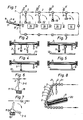
- Figure 1 is a schematic side view of the machine;
- Figures 2 - 5 are respective sectional views taken on the lines II - II to V - V in Figure 1;
- Figures 6 and 7 are respective cross-sectional views of a collecting element and a delivery element during transfer of an item to a collecting container in a delivery station; and
- Figure 8 is a part view similar to Figure 1, illustrating schematically a modified machine incorporating an internally located delivery station.
- The machine illuatrated in Figure 1 comprises an endless conveyor path or belt 1 which is provided with permanently magnetized collecting elements in the form of
rods 2. The rods, orcylinders 2, are arranged to move clockwise along a rectangular path in mutually spaced relationship, with the spacing between adjacent rods being slightly greater than the length of the longest item, the knives 3, to be sorted in accordance with length. Remaining items of cutlery in a decreasing order of length may include serving spoons 4,forks 5, and tea spoons 6. The devices used to drive and control therods 2 along the endless path 1 are of a conventional kind and need not therefore be described and illustrated here. Incorporated in the upwardly moving part of the endless path or belt 1 is a collecting station A, while delivery stations B, C, D and E for receiving knives 3, serving spoons 4,forks 5, and teaspoons 6 are located along the upper horizontal part of the endless belt. - The various items of cutlery are delivered to the machine on an inclined plate 7 provided with ridges 7' which guide the items of cutlery, orientated with their longitudinal axes in the direction of movement, until stopped with one end against a thin plastic bar 8. The bar 8 is located so that the
magnetic rods 2, which function as collectors, slide along the outer surface of the bar. Since both ends of each item of cutlery are magnetic, it is unimportant which end of said item rests against the bar 8. All items of cutlery that rest with one end thereof against the bar 8 as amagnetic rod 2 passes by are attracted magnetically by the rod, so as to be lifted by one end and hang vertically from the collecting rod as it moves away from the bar. - Naturally, the bar 8 will slightly impair the attractive force of the
magnetic rods 2 on the ends of respective items of cutlery during the actual moment of lifting said item. This can be overcome, however, by providing the bar with narrow upwardly extending fingers which permit direct contact between amagnetic rod 2 and the ends of respective items of cutlery at the precise moment of lifting said items, therewith to afford a camming action. - Each of the delivery stations B - E has arranged therein respective magnetic delivery elements 11 - 14 which have the form of magnetic rods of the same length as the
magnetic rods 2 and which are spaced from the under surfaces of therods 2 when said rods are located immediately above the rods 11 - 14, this spacing being equal to or some millimeters shorter than the length of the items of cutlery 3 - 6 in the aforesaid classifying order, i.e. the distance between the mutually opposedrods 2 and 11 - 14 decreases from a distance commensurate with the length of knives 3 to a distance commensurate with the spoons 6. - Collecting
containers 15 are placed beneath the delivery elements 11 - 14 and to one side thereof as seen in the upstream direction of the path or belt 1. Thecontainers 15 may alternatively be replaced with transverse conveyors or sloping chutes, or equivalent devices. - The magnetic attraction force exerted by the magnetic rods 11 - 14 is greater than that exerted by the
magnetic rods 2, so that when the depending end of an item of cutlery carried by arod 2 contacts an underlying rod 11 - 14, depending upon the length of said item, this item of cutlery becomes positively attached to the magnetic rod 11 - 14 and is consequently wrenched from therod 2 of weaker magnetism as said rod moves to the right in Figure 1 along said path 1. As a result hereof the aforesaid item of cutlery will swing clockwise with a momentum sufficient to break the grip of the relevant magnetic rod 11 - 14. In order to render it impossible for an item of cutlery to remain attached to a particular magnetic rod 11 - 14, means may be provided for momentarily demagnetizing the rods, either electrically or mechanically, during each delivery sequence or during given delivery sequences. A simpler but equally effective solution to this problem is illustrated in Figures 6 and 7. In this embodiment each magnetic delivery rod 11 - 14 is provided on its underside, and to the right as seen in the drawing, with a surround 16 of non-magnetic material. The under part of thesurround 16 prevents upwardly bouncing cutlery items from becoming attached to an adjacent magnetic rod while the right-hand edge of the surround serves as an effective dislodging element which forces the attracted end of said cutlery item away from the actual magnetic rods 11 - 14, as illustrated in Figure 7. - The manner in which the machine operates will be seen from Figures 2 - 5. As illustrated in Figure 2, in delivery station B the
magnetic collecting rod 2 has depending therefrom a number of items of cutlery, which may comprise all of the aforesaid four different categories. Only the knives 3 have a length sufficient to be attracted by theunderlying delivery rod 11 and drawn free from thecollecting rod 2 and dropped into the associatedcontainer 15. - The collecting
rods 2 move further to the delivery station C, Figure 3, where only serving spoons, of sufficient length to be magnetically attracted and drawn loose from themagnetic rod 2 by the underlying delivery rod orelement 12 , are thrown into theappropriate container 15. - In the delivery station D, Figure 4, only the forks have a length sufficient to be attracted and pulled loose by the delivery rod or
element 13 and thrown into theappropriate container 15. - Finally, only the tea spoons 6 remain when the
collecting rod 2 arrives at delivery station E, Figure 5, these spoons being pulled loose by the underlying rod or element 14 and delivered to theappropriate container 15. - It will be appreciated that the delivery stations B - E can be readily extended to include sorting stations for other items of cutlery, such as dessert spoons, butter knives, etc. The only necessity in this regard is that there is a difference in length between the items of each category to be sorted. This length difference can be as small as from two to three millimeters, since the delivery rods or elements 11 - 14 collecting the items from the
rods 2 can be positioned and regulated with a high degree of accuracy in relation to the movement path of thecollecting rods 2. - The
magnetic collecting rods 2 can be driven at high speed, so as to achieve a high sorting capacity. - The sorting capacity can be increased still further by means of the embodiment illustrated in Figure 8. In this embodiment the various items of cutlery are fed to the collecting station A from a location within the endless conveyor path 1 instead of from a location external of said path, the cutlery in this embodiment being advanced on an inclined
endless conveyor belt 20. The magnetic collecting rods of this embodiment can be placed much closer together, optionally separated by intermediatenon-magnetic spacer rods 21, since in this embodiment the items of cutlery need not pass between themagnetic rods 2. The upwardly rising part of the conveyor path 1, however, must slope rearwardly to some extent, as shown in Figure 8, so that individual items of cutlery can be lifted by amagnetic collecting rod 2 to a vertical position without coming into contact with anunderlying rod 2. Consequently in this embodiment the respective items of cutlery will be displaced rearwardly during the initial stage of this lifting movement, although to no disadvantage. - It will be understood that the invention is not restricted to machine constructions for sorting items of cutlery and that the principles of the invention can be used in conjunction with other sorting machines and apparatus, such as machines for sorting machine components, fittings, etc. made of a magnetic or magnetizable material.
Claims (3)
Applications Claiming Priority (2)
| Application Number | Priority Date | Filing Date | Title |
|---|---|---|---|
| SE8504064 | 1985-09-02 | ||
| SE8504064A SE446691B (en) | 1985-09-02 | 1985-09-02 | MACHINE FOR SORTING STAND-FORM OF MAGNETIC MATERIAL |
Publications (3)
| Publication Number | Publication Date |
|---|---|
| EP0213100A2 true EP0213100A2 (en) | 1987-03-04 |
| EP0213100A3 EP0213100A3 (en) | 1988-02-03 |
| EP0213100B1 EP0213100B1 (en) | 1989-10-11 |
Family
ID=20361259
Family Applications (1)
| Application Number | Title | Priority Date | Filing Date |
|---|---|---|---|
| EP86850272A Expired EP0213100B1 (en) | 1985-08-30 | 1986-08-08 | A cutlery sorting machine |
Country Status (6)
| Country | Link |
|---|---|
| US (1) | US4744469A (en) |
| EP (1) | EP0213100B1 (en) |
| AT (1) | ATE47052T1 (en) |
| DE (1) | DE3666154D1 (en) |
| FI (1) | FI84983C (en) |
| SE (1) | SE446691B (en) |
Families Citing this family (10)
| Publication number | Priority date | Publication date | Assignee | Title |
|---|---|---|---|---|
| US5237801A (en) * | 1991-09-26 | 1993-08-24 | Technistar Corporation | Automated utensil packaging system |
| DE4344594C1 (en) * | 1993-12-24 | 1995-05-24 | Joerg Zaubitz | Automatic sorting device for shaped objects e.g. cutlery |
| US5996809A (en) * | 1997-05-07 | 1999-12-07 | Chiasson; Robert H. | Flatware sorting machine |
| US6352160B1 (en) | 2000-05-24 | 2002-03-05 | Rowland S. Harden | System and method for capturing ferrous articles from food waste systems |
| DE102006061839B4 (en) * | 2006-12-21 | 2013-04-25 | Brimato Technologie Gmbh | Method for sorting different ferromagnetic cutlery pieces and device for carrying out the method |
| US7905341B1 (en) * | 2007-05-17 | 2011-03-15 | Alpha 1 Induction Service Center, Inc. | Handling system for multiple workpieces |
| WO2011106763A1 (en) * | 2010-02-28 | 2011-09-01 | Greg Chaganos | Utensil sorting apparatus |
| US9045884B1 (en) * | 2011-12-19 | 2015-06-02 | Rowland S. Harden | System and method for capturing ferrous items from food waste systems |
| CN104907172B (en) * | 2015-06-12 | 2017-03-29 | 上海电机学院 | A kind of Full-automatic tableware sorting equipment and its method for sorting |
| CN106216089B (en) * | 2016-08-31 | 2018-07-24 | 陶宇 | A kind of sorting equipment of chopsticks |
Citations (5)
| Publication number | Priority date | Publication date | Assignee | Title |
|---|---|---|---|---|
| FR582599A (en) * | 1924-06-07 | 1924-12-22 | Measuring device | |
| US2705072A (en) * | 1954-03-31 | 1955-03-29 | United States Steel Corp | Apparatus for automatically assorting angle-irons and the like to length |
| DE1920141A1 (en) * | 1968-05-07 | 1970-09-17 | Inst Schiffbau | Method and device for the transport and sorting of irregularly shaped parts made of magnetizable materials |
| US3545613A (en) * | 1968-10-11 | 1970-12-08 | Economics Lab | Sorting various pieces of silverware by kind and size |
| US3625356A (en) * | 1970-06-08 | 1971-12-07 | Dynasort Corp | Apparatus for continuously sorting long, slender articles by length |
Family Cites Families (7)
| Publication number | Priority date | Publication date | Assignee | Title |
|---|---|---|---|---|
| CA835738A (en) * | 1970-03-03 | W. Lewis James | Inspection machine for flares | |
| GB873869A (en) * | 1958-04-28 | 1961-07-26 | Alan Stewart Fitzgerald | Device for sorting cylindrical objects according to their diameters |
| US3498452A (en) * | 1968-05-16 | 1970-03-03 | Ibm | Pin length sorter |
| US3938533A (en) * | 1973-10-29 | 1976-02-17 | Wilton Richard | Automatic scullery system |
| SU671867A1 (en) * | 1975-04-15 | 1979-07-05 | Maksimov Semen | Apparatus for sorting articles by size |
| US4262805A (en) * | 1979-08-09 | 1981-04-21 | Western Electric Company, Inc. | Distinguishing elongated articles according to their shape |
| US4356905A (en) * | 1980-10-06 | 1982-11-02 | Western Electric Co., Inc. | Removing magnetic articles from a carrier |
-
1985
- 1985-09-02 SE SE8504064A patent/SE446691B/en not_active IP Right Cessation
-
1986
- 1986-08-08 DE DE8686850272T patent/DE3666154D1/en not_active Expired
- 1986-08-08 AT AT86850272T patent/ATE47052T1/en not_active IP Right Cessation
- 1986-08-08 EP EP86850272A patent/EP0213100B1/en not_active Expired
- 1986-08-26 FI FI863456A patent/FI84983C/en not_active IP Right Cessation
- 1986-08-29 US US06/901,686 patent/US4744469A/en not_active Expired - Fee Related
Patent Citations (5)
| Publication number | Priority date | Publication date | Assignee | Title |
|---|---|---|---|---|
| FR582599A (en) * | 1924-06-07 | 1924-12-22 | Measuring device | |
| US2705072A (en) * | 1954-03-31 | 1955-03-29 | United States Steel Corp | Apparatus for automatically assorting angle-irons and the like to length |
| DE1920141A1 (en) * | 1968-05-07 | 1970-09-17 | Inst Schiffbau | Method and device for the transport and sorting of irregularly shaped parts made of magnetizable materials |
| US3545613A (en) * | 1968-10-11 | 1970-12-08 | Economics Lab | Sorting various pieces of silverware by kind and size |
| US3625356A (en) * | 1970-06-08 | 1971-12-07 | Dynasort Corp | Apparatus for continuously sorting long, slender articles by length |
Also Published As
| Publication number | Publication date |
|---|---|
| DE3666154D1 (en) | 1989-11-16 |
| FI863456A (en) | 1987-03-01 |
| US4744469A (en) | 1988-05-17 |
| FI84983C (en) | 1992-02-25 |
| FI863456A0 (en) | 1986-08-26 |
| ATE47052T1 (en) | 1989-10-15 |
| SE446691B (en) | 1986-10-06 |
| EP0213100B1 (en) | 1989-10-11 |
| EP0213100A3 (en) | 1988-02-03 |
| FI84983B (en) | 1991-11-15 |
| SE8504064D0 (en) | 1985-09-02 |
Similar Documents
| Publication | Publication Date | Title |
|---|---|---|
| EP0213100A2 (en) | A cutlery sorting machine | |
| US4601396A (en) | Method and device for sorting flat and indexed articles | |
| GR3020768T3 (en) | Distributing and collecting device for products to be conveyed | |
| JPS612611A (en) | Belt conveyor | |
| JPS61178817A (en) | Method and device for forwarding box to position of packaging | |
| US3537580A (en) | Methods of and apparatus for storing and testing paramagnetic articles | |
| WO1986007338A1 (en) | Sorting device for belt conveyors systems | |
| AU3411600A (en) | Sorting system for soft article such as garments | |
| EP0208024B1 (en) | Apparatus for sorting and removing undesirable objects from a feed belt conveyor | |
| US3621979A (en) | Magnetic conveyor system | |
| US5301809A (en) | Sorting conveyor | |
| US5538140A (en) | Buffered stacker with drop floor assembly | |
| US4593805A (en) | System for sorting containers | |
| WO1999048622A1 (en) | Modular link conveyor belt package sortation system | |
| EP0589821B1 (en) | Sorting apparatus | |
| US4738367A (en) | Magnetic refuse separator | |
| EP0593126B1 (en) | Sorting conveyor with magnetic discharge | |
| US6755606B2 (en) | Jogging apparatus | |
| US3645378A (en) | Edge feed transport system for document sorting and stacking | |
| US3308924A (en) | Article check-weighing and segregating apparatus | |
| US4895300A (en) | Passive mail facing device | |
| GB2104228A (en) | Sorting by weighing | |
| US6564922B1 (en) | Flex diverter | |
| US2651402A (en) | Assorting and forwarding mechanism | |
| EP0376402A1 (en) | Intermediate element or signalizing member |
Legal Events
| Date | Code | Title | Description |
|---|---|---|---|
| PUAI | Public reference made under article 153(3) epc to a published international application that has entered the european phase |
Free format text: ORIGINAL CODE: 0009012 |
|
| AK | Designated contracting states |
Kind code of ref document: A2 Designated state(s): AT BE CH DE FR GB IT LI NL |
|
| PUAL | Search report despatched |
Free format text: ORIGINAL CODE: 0009013 |
|
| AK | Designated contracting states |
Kind code of ref document: A3 Designated state(s): AT BE CH DE FR GB IT LI NL |
|
| 17P | Request for examination filed |
Effective date: 19880122 |
|
| 17Q | First examination report despatched |
Effective date: 19880505 |
|
| GRAA | (expected) grant |
Free format text: ORIGINAL CODE: 0009210 |
|
| AK | Designated contracting states |
Kind code of ref document: B1 Designated state(s): AT BE CH DE FR GB IT LI NL |
|
| REF | Corresponds to: |
Ref document number: 47052 Country of ref document: AT Date of ref document: 19891015 Kind code of ref document: T |
|
| ET | Fr: translation filed | ||
| REF | Corresponds to: |
Ref document number: 3666154 Country of ref document: DE Date of ref document: 19891116 |
|
| ITF | It: translation for a ep patent filed | ||
| PLBE | No opposition filed within time limit |
Free format text: ORIGINAL CODE: 0009261 |
|
| STAA | Information on the status of an ep patent application or granted ep patent |
Free format text: STATUS: NO OPPOSITION FILED WITHIN TIME LIMIT |
|
| 26N | No opposition filed | ||
| PGFP | Annual fee paid to national office [announced via postgrant information from national office to epo] |
Ref country code: GB Payment date: 19910808 Year of fee payment: 6 |
|
| PGFP | Annual fee paid to national office [announced via postgrant information from national office to epo] |
Ref country code: CH Payment date: 19910827 Year of fee payment: 6 |
|
| PGFP | Annual fee paid to national office [announced via postgrant information from national office to epo] |
Ref country code: FR Payment date: 19910830 Year of fee payment: 6 |
|
| ITTA | It: last paid annual fee | ||
| PGFP | Annual fee paid to national office [announced via postgrant information from national office to epo] |
Ref country code: NL Payment date: 19910831 Year of fee payment: 6 Ref country code: AT Payment date: 19910831 Year of fee payment: 6 |
|
| PGFP | Annual fee paid to national office [announced via postgrant information from national office to epo] |
Ref country code: BE Payment date: 19910904 Year of fee payment: 6 |
|
| PGFP | Annual fee paid to national office [announced via postgrant information from national office to epo] |
Ref country code: DE Payment date: 19910910 Year of fee payment: 6 |
|
| PG25 | Lapsed in a contracting state [announced via postgrant information from national office to epo] |
Ref country code: GB Effective date: 19920808 Ref country code: AT Effective date: 19920808 |
|
| PG25 | Lapsed in a contracting state [announced via postgrant information from national office to epo] |
Ref country code: LI Effective date: 19920831 Ref country code: CH Effective date: 19920831 Ref country code: BE Effective date: 19920831 |
|
| BERE | Be: lapsed |
Owner name: SWALLERT SVEN Effective date: 19920831 |
|
| PG25 | Lapsed in a contracting state [announced via postgrant information from national office to epo] |
Ref country code: NL Effective date: 19930301 |
|
| GBPC | Gb: european patent ceased through non-payment of renewal fee |
Effective date: 19920808 |
|
| NLV4 | Nl: lapsed or anulled due to non-payment of the annual fee | ||
| PG25 | Lapsed in a contracting state [announced via postgrant information from national office to epo] |
Ref country code: FR Effective date: 19930430 |
|
| REG | Reference to a national code |
Ref country code: CH Ref legal event code: PL |
|
| PG25 | Lapsed in a contracting state [announced via postgrant information from national office to epo] |
Ref country code: DE Effective date: 19930501 |
|
| REG | Reference to a national code |
Ref country code: FR Ref legal event code: ST |
|
| PG25 | Lapsed in a contracting state [announced via postgrant information from national office to epo] |
Ref country code: IT Free format text: LAPSE BECAUSE OF NON-PAYMENT OF DUE FEES;WARNING: LAPSES OF ITALIAN PATENTS WITH EFFECTIVE DATE BEFORE 2007 MAY HAVE OCCURRED AT ANY TIME BEFORE 2007. THE CORRECT EFFECTIVE DATE MAY BE DIFFERENT FROM THE ONE RECORDED. Effective date: 20050808 |