EP0212638B1 - Selbstschneidende Gewindebuchse für Kunststoffe - Google Patents
Selbstschneidende Gewindebuchse für Kunststoffe Download PDFInfo
- Publication number
- EP0212638B1 EP0212638B1 EP86111573A EP86111573A EP0212638B1 EP 0212638 B1 EP0212638 B1 EP 0212638B1 EP 86111573 A EP86111573 A EP 86111573A EP 86111573 A EP86111573 A EP 86111573A EP 0212638 B1 EP0212638 B1 EP 0212638B1
- Authority
- EP
- European Patent Office
- Prior art keywords
- thread
- threads
- threaded bushing
- self
- reduction
- Prior art date
- Legal status (The legal status is an assumption and is not a legal conclusion. Google has not performed a legal analysis and makes no representation as to the accuracy of the status listed.)
- Expired
Links
- 229920003023 plastic Polymers 0.000 title claims description 10
- 239000004033 plastic Substances 0.000 title claims description 10
- 238000010079 rubber tapping Methods 0.000 title description 3
- 239000000463 material Substances 0.000 claims description 6
- 238000004519 manufacturing process Methods 0.000 description 3
- 238000003754 machining Methods 0.000 description 2
- 230000001154 acute effect Effects 0.000 description 1
- 230000037431 insertion Effects 0.000 description 1
- 238000003780 insertion Methods 0.000 description 1
Images
Classifications
-
- F—MECHANICAL ENGINEERING; LIGHTING; HEATING; WEAPONS; BLASTING
- F16—ENGINEERING ELEMENTS AND UNITS; GENERAL MEASURES FOR PRODUCING AND MAINTAINING EFFECTIVE FUNCTIONING OF MACHINES OR INSTALLATIONS; THERMAL INSULATION IN GENERAL
- F16B—DEVICES FOR FASTENING OR SECURING CONSTRUCTIONAL ELEMENTS OR MACHINE PARTS TOGETHER, e.g. NAILS, BOLTS, CIRCLIPS, CLAMPS, CLIPS OR WEDGES; JOINTS OR JOINTING
- F16B25/00—Screws that cut thread in the body into which they are screwed, e.g. wood screws
- F16B25/0036—Screws that cut thread in the body into which they are screwed, e.g. wood screws characterised by geometric details of the screw
- F16B25/0042—Screws that cut thread in the body into which they are screwed, e.g. wood screws characterised by geometric details of the screw characterised by the geometry of the thread, the thread being a ridge wrapped around the shaft of the screw
- F16B25/0047—Screws that cut thread in the body into which they are screwed, e.g. wood screws characterised by geometric details of the screw characterised by the geometry of the thread, the thread being a ridge wrapped around the shaft of the screw the ridge being characterised by its cross-section in the plane of the shaft axis
-
- F—MECHANICAL ENGINEERING; LIGHTING; HEATING; WEAPONS; BLASTING
- F16—ENGINEERING ELEMENTS AND UNITS; GENERAL MEASURES FOR PRODUCING AND MAINTAINING EFFECTIVE FUNCTIONING OF MACHINES OR INSTALLATIONS; THERMAL INSULATION IN GENERAL
- F16B—DEVICES FOR FASTENING OR SECURING CONSTRUCTIONAL ELEMENTS OR MACHINE PARTS TOGETHER, e.g. NAILS, BOLTS, CIRCLIPS, CLAMPS, CLIPS OR WEDGES; JOINTS OR JOINTING
- F16B25/00—Screws that cut thread in the body into which they are screwed, e.g. wood screws
- F16B25/001—Screws that cut thread in the body into which they are screwed, e.g. wood screws characterised by the material of the body into which the screw is screwed
- F16B25/0015—Screws that cut thread in the body into which they are screwed, e.g. wood screws characterised by the material of the body into which the screw is screwed the material being a soft organic material, e.g. wood or plastic
-
- F—MECHANICAL ENGINEERING; LIGHTING; HEATING; WEAPONS; BLASTING
- F16—ENGINEERING ELEMENTS AND UNITS; GENERAL MEASURES FOR PRODUCING AND MAINTAINING EFFECTIVE FUNCTIONING OF MACHINES OR INSTALLATIONS; THERMAL INSULATION IN GENERAL
- F16B—DEVICES FOR FASTENING OR SECURING CONSTRUCTIONAL ELEMENTS OR MACHINE PARTS TOGETHER, e.g. NAILS, BOLTS, CIRCLIPS, CLAMPS, CLIPS OR WEDGES; JOINTS OR JOINTING
- F16B37/00—Nuts or like thread-engaging members
- F16B37/12—Nuts or like thread-engaging members with thread-engaging surfaces formed by inserted coil-springs, discs, or the like; Independent pieces of wound wire used as nuts; Threaded inserts for holes
- F16B37/122—Threaded inserts, e.g. "rampa bolts"
- F16B37/125—Threaded inserts, e.g. "rampa bolts" the external surface of the insert being threaded
- F16B37/127—Threaded inserts, e.g. "rampa bolts" the external surface of the insert being threaded and self-tapping
Definitions
- the invention relates to a self-tapping threaded bush for plastic parts with the features specified in the preamble of claim 1.
- Such threaded bushings are intended for insertion into parts made of relatively soft but also brittle plastics in order to increase the load-bearing capacity and the wear resistance in the case of repeatedly releasable screw connections.
- the threaded bushing is screwed into a hole and thereby cuts its thread itself. The material displaced during thread cutting is pressed into the spaces between the threads.
- the forming tool for producing the thread has a certain width, so that a part of the screw shaft below the screw head cannot be provided with the thread.
- the object on which the invention is based is to further develop the threaded bushing of the type described at the outset such that its load-bearing capacity is further increased when it is screwed into plastic parts and the manufacture of such bushings is simplified.
- the thread form itself increases the load capacity of the thread. If the constriction is located directly on the front flank of the threads as viewed in the screwing direction, the material displaced when screwing in can enter the fillet directly.
- the rear flank of the threads as seen in the screwing direction together with the ramps tapering towards the rounding conveys a very high load-bearing capacity in the plastic, due to the flat flank acting in the pull-out direction and the high thread friction coefficient.
- the outer surface of the threaded bushing can be provided with the load-bearing thread in a simple manner over its entire length before the ring flange is attached. This also increases the load capacity, since the thread length has increased with the length of the bushing unchanged.
- the production of such threaded bushings by means of machining deformation does not have to start from the outer diameter of the flange, but from the outer thread diameter, so that the machining work is considerably less and the production is more economical.
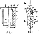
- the threaded bushing 10 shown in FIG. 1 has a continuous internal thread 11 and an external thread 12 for screwing the threaded bushing into a part made of plastic.
- a recess 14 is milled in a known manner on the front of the threaded bushing.
- the threaded bushing has a flange 15, so that the bushing can only be screwed into the plastic until the underside of the flange 15 lies on the plastic surface and then this flange forms a counter bearing for the part to be fastened.
- a cylindrical tube with the outside diameter D a and the inside diameter Di is assumed and the inside thread 11 and the outside thread 12 are made.
- the sleeves are then cut to length and a collar 16 is formed through a recess on the outer circumference, the length of which is equal to the thickness of the ring flange 15 after riveting.
- the annular disc 15 is placed on the collar 16 and then riveted by slightly conically widening the collar 16. In this way, the entire length of the threaded bushing 10 can be provided with the external thread 12.
- the external thread 12 thus extends right under the flange 15.
- the profile of the external thread 12 is shown in detail in FIG. 2.
- the pitch h of the threads 18 is large and the outside diameter Da is relatively large compared to the core diameter D k , so that there are relatively large radial lengths of the front flanks 19 and rear flanks 20 - in each case seen in the screwing direction - result.
- the core diameter D k lies on the dashed line 22 that cuts through the foot 21 of the threads 18. This line 22 also forms the core hole diameter for the self-cutting thread, the foot 21 ensuring centering and preventing skewing.
- a constriction 24 is provided between the successive thread gears 18 in order to accommodate the material displaced inward by the thread turns when the threaded bushing is screwed in.
- This constriction 24 is formed by the profile shown in Figure 2. Here lies the narrowest point 25 of the constriction 24 in the immediate vicinity of the respective front flank 19 of the threads. As can be seen from FIG. 2, the constriction 25 adjoins the front flank 19 via a relatively small radius of curvature.
- the front flank 19 extends essentially perpendicular to the longitudinal axis of the threaded bushing in order to reduce the friction to a minimum when the thread is cut by itself.
- the respective rear flank 20 of the threads 18, however, runs at an acute angle to the front of the front flank.
- the profile 24 tapers uniformly along a relatively long ramp 26 to the constriction 25.
- the profile shown in Figure 2 can also be used for bolts.
- the outer diameter Da is 14 mm
- the core diameter is 13.2 mm
- the diameter at the point of the constriction 25 is 12.6 mm.
- the angle between the front flank 19 and the perpendicular to the longitudinal axis is 3 ° and the angle of the rear flank 20 to the vertical is 30 ° . This corresponds to the DIN regulation for sawtooth profiles.
- the angle between line 22 and ramp 26 is 15 ° .
- the radius of curvature between the front flank 19 and the constriction 25 is 0.5 mm and the pitch h is 2 mm.
Landscapes
- Engineering & Computer Science (AREA)
- General Engineering & Computer Science (AREA)
- Mechanical Engineering (AREA)
- Life Sciences & Earth Sciences (AREA)
- Chemical & Material Sciences (AREA)
- Dispersion Chemistry (AREA)
- Wood Science & Technology (AREA)
- Physics & Mathematics (AREA)
- Geometry (AREA)
- Bolts, Nuts, And Washers (AREA)
- Dowels (AREA)
Description
- Die Erfindung betrifft eine selbstschneidende Gewindebuchse für Teile aus Kunststoff mit den im Oberbegriff des Patentanspruchs 1 angegebenen Merkmalen.
- Derartige Gewindebuchsen sind zum Einsetzen in Teile aus verhältnismässig weichen aber auch spröden Kunststoffen bestimmt, um die Tragfähigkeit und die Verschleissfestigkeit bei wiederholt lösbaren Schraubverbindungen zu erhöhen. Infolge des grossen Aussendurchmessers der Gewindegänge gegenüber dem Kerndurchmesser und der grossen Steigung der Gewindegänge ergibt sich eine verhältnismässig grosse Tragkraft, wenn die Gewindebuchse in eine Bohrung eingedreht wird und dabei ihr Gewinde selbst einschneidet. Dabei wird das beim Gewindeschneiden verdrängte Material in die Zwischenräume zwischen die Gewidegänge gedrückt. Es ist bekannt (DE-C 2 754 870), zwischen den Gewindegängen im Bereich des Kerns einer Schraube eine Einschnürung vorzusehen, welche zur Aufnahme des beim Eindrehen von den Gewindegängen verdrängten Werkstoffs dient, so dass die Gewindegänge voll bis zu ihrem Fuss hin in das Material eindringen können und damit die Tragkraft vergrössert wird. Von der mittig zwischen den Gewindegängen liegenden Einschnürung aus steigt das Profil jeweils geradlinig zu den Fusspunkten der Gewindegänge an. Bei einer anderen bekannten gewindeselbstformenden Schraube (EP-A 0 088 366) vergrössert sich der Flankenwinkel von der Spitze jedes Gewindegangs aus stetig bis zum Gewindegrund. Auch hier ist das Gewindeprofil symmetrisch.
- Das Formwerkzeug zum Herstellen des Gewindes weist eine bestimmte Breite auf, so dass ein Teil des Schraubenschaftes unterhalb des Schraubenkopfes nicht mit dem Gewinde versehen werden kann.
- Die der Erfindung zugrundeliegende Aufgabe besteht darin, die Gewindebuchse der eingangs geschilderten Art so weiterzubilden, dass ihre Tragkraft beim Eindrehen in Teile aus Kunststoff weiter erhöht und die Fertigung solcher Buchsen vereinfacht wird.
- Durch die Gewindeform selbst wird die Tragfähigkeit des Gewindes erhöht. Wenn sich die Einschnürung unmittelbar an der in Einschraubrichtung gesehen vorderen Flanke der Gewindegänge befindet, kann dort das beim Eindrehen verdrängte Material unmittelbar in die Ausrundung eintreten. Die in Einschraubrichtung gesehen hintere Flanke der Gewindegänge zusammen mit den zur Ausrundung hin konisch sich verjüngenden Rampen vermittelt eine sehr hohe Tragkraft in dem Kunststoff, auf Grund der in Auszugsrichtung wirkenden flachen Flanke und dem dadurch hohen Gewindereibwertanteil.
- Ist darüber hinaus der als Anschlag dienende Flansch der Gewindebuchse an dieser angenietet, so kann vor dem Befestigen des Ringflansches die Außenfläche der Gewindebuchse über ihre gesamte Länge hinweg in einfacher Weise mit dem tragenden Gewinde versehen werden. Damit ist ebenfalls die Tragfähigkeit vergrößert, da die Gewindelänge bei unveränderter Länge der Buchse größer geworden ist. Außerdem muß bei der Herstellung solcher Gewindebuchsen mittels spanender Verformung nicht vom Außendurchmesser des Flansches, sondern vom Gewindeaußendurchmesser ausgegangen werden, so daß die Zerspanungsarbeit wesentlich geringer und die Herstellung wirtschaftlicher ist.
- Ein Ausführungsbeispiel der Erfindung ist nachstehend anhand der Zeichnung näher erläutert. Es zeigt:
- Fig. 1 eine Ansicht bzw. einen Schnitt durch eine Gewindebuchse und
- Fig. 2 eine vergrößerte Darstellung des Gewindeprofils der Gewindebuchse.
- Die in Figur 1 dargestellte Gewindebuchse 10 weist ein durchgehendes Innengewinde 11 und ein Außengewinde 12 zum Eindrehen der Gewindebuchse in ein Teil aus Kunststoff auf. Um das Selbstschneiden des Gewindes zu verbessern, ist in bekannter Weise an der Vorderseite der Gewindebuchse eine Ausnehmung 14 eingefräst. Ferner weist die Gewindebuchse einen Flansch 15 auf, so daß die Buchse nur so weit in den Kunststoff eingeschraubt werden kann, bis sich die Unterseite des Flansches 15 auf die Kunststoffoberfläche auflegt und anschließend dieser Flansch ein Gegenlager für das zu befestigende Teil bildet.
- Zur Herstellung der Gewindebuchse wird von einem zylindrischen Rohr mit dem Außendurchmesser Da und dem Innendurchmesser Di ausgegangen und das Innengewinde 11 und das Außengewinde 12 angefertigt. Anschließend werden die Buchsen abgelängt und durch eine Ausnehmung am Außenumfang ein Kragen 16 ausgebildet, dessen Länge gleich der Dicke des Ringflansches 15 nach dem Vernieten ist. Die Ringscheibe 15 wird auf den Kragen 16 aufgesetzt und dann durch leicht konisches Aufweiten des Kragens 16 eine Vernietung herbeigeführt. Auf diese Weise kann die gesamte Länge der Gewindebuchse 10 mit dem Außengewinde 12 versehen werden. Das Außengewinde 12 reicht also bis unmittelbar unter den Flansch 15 heran.
- Das Profil des Außengewindes 12 ist in Figur 2 im einzelnen dargestellt. Um eine hohe Tragkraft in weiche und auch spröde Kunststoffe zu erzielen, ist die Steigung h der Gewindegänge 18 groß und der Außendurchmesser Da gegenüber dem Kerndurchmesser Dk verhältnismäßig groß, so daß sich verhältnismäßig große radiale Längen der vorderen Flanken 19 und hinteren Flanken 20 - jeweils in Einschraubrichtung gesehen - ergeben. In Figur 2 liegt der Kerndurchmesser Dk auf der durch den Fuß 21 der Gewindegänge 18 schneidenden gestrichelten Linie 22. Diese Linie 22 bildet auch den Kernlochdurchmesser für das selbstzuschneidende Gewinde, wobei der Fuß 21 für eine Zentrierung sorgt und ein Schiefeinlaufen verhindert.
- Um das beim Eindrehen der Gewindebuchse von den Gewindegängen nach innen verdrängte Material aufzunehmen, ist eine Einschnürung 24 zwischen den aufeinanderfolgenden Gewindegähgen 18 vorgesehen. Diese Einschnürung 24 wird von dem in Figur 2 dargestellten Profil gebildet. Dabei liegt die engste Stelle 25 der Einschnürung 24 in unmittelbarer Nähe der jeweils vorderen Flanke 19 der Gewindegänge. Wie aus Figur 2 erkennbar ist, schließt sich die Einschnürung 25 über einen verhältnismäßig kleinen Krümmungsradius an die Vorderflanke 19 an. Die Vorderflanke 19 verläuft im wesentlichen senkrecht zur Längsachse der Gewindebuchse, um beim Selbstschneiden des Gewindes die Reibung auf ein Mindestmaß zu reduzieren.
- Die jeweils hintere Flanke 20 der Gewindegänge 18 verläuft dagegen in einem spitzen Winkel zur Front der Vorderflanke. Vom Fuß 21 der hinteren Flanke 20 ausgehend verjüngt sich das Profil 24 längs einer verhältnismäßig langen Rampe 26 gleichmäßig bis zur Einschnürung 25.
- Das in Figur 2 dargestellte Profil kann auch für Bolzen Verwendung finden. Bei einem Ausführungsbeispiel für eine Gewindebuchse mit M10 als Innengewinde beträgt der Außendurchmesser Da 14 mm, der Kerndurchmesser 13,2 mm und der Durchmesser an der Stelle der Einschnürung 25 beträgt 12,6 mm. Der Winkel zwischen der Vorderflanke 19 und der Senkrechten zur Längsachse beträgt 3° und der Winkel der hinteren Flanke 20 zur Senkrechten 30°. Dies entspricht der DIN-Vorschrift für Sägezahnprofile.
- Der Winkel zwischen der Linie 22 und der Rampe 26 beträgt 15°. Der Krümmungsradius zwischen der vorderen Flanke 19 und der Einschnürung 25 beträgt 0,5 mm und die Steigung h beträgt 2 mm.
Claims (3)
Applications Claiming Priority (2)
| Application Number | Priority Date | Filing Date | Title |
|---|---|---|---|
| DE3530083 | 1985-08-22 | ||
| DE19853530083 DE3530083A1 (de) | 1985-08-22 | 1985-08-22 | Selbstschneidende gewindebuchse fuer kunststoffe |
Publications (2)
| Publication Number | Publication Date |
|---|---|
| EP0212638A1 EP0212638A1 (de) | 1987-03-04 |
| EP0212638B1 true EP0212638B1 (de) | 1989-03-29 |
Family
ID=6279136
Family Applications (1)
| Application Number | Title | Priority Date | Filing Date |
|---|---|---|---|
| EP86111573A Expired EP0212638B1 (de) | 1985-08-22 | 1986-08-21 | Selbstschneidende Gewindebuchse für Kunststoffe |
Country Status (3)
| Country | Link |
|---|---|
| EP (1) | EP0212638B1 (de) |
| DE (2) | DE3530083A1 (de) |
| ES (1) | ES2002474A6 (de) |
Cited By (1)
| Publication number | Priority date | Publication date | Assignee | Title |
|---|---|---|---|---|
| DE202016102461U1 (de) | 2016-04-15 | 2016-05-25 | Fairchild Fasteners Europe - Camloc Gmbh | Selbstschneidender Gewindeeinsatz |
Families Citing this family (5)
| Publication number | Priority date | Publication date | Assignee | Title |
|---|---|---|---|---|
| US5061135A (en) * | 1990-08-28 | 1991-10-29 | Research Engineering & Manufacturing, Inc. | Thread tapping screw |
| DE102004021484B4 (de) | 2004-04-30 | 2018-11-29 | Böllhoff Verbindungstechnik GmbH | Verfahren zum Herstellen einer Verbindungsanordnung |
| DE102005048088A1 (de) * | 2005-09-30 | 2007-04-05 | Adolf Würth GmbH & Co. KG | Gewindebuchse, Verfahren zum Erneuern eines Gewindes und Werkzeug hierfür |
| DE102006008662B4 (de) * | 2006-02-24 | 2010-04-01 | Audi Ag | Bohrung in einem weichen Kunststoffteil und Montageanordnung |
| DE102008054807A1 (de) * | 2008-12-17 | 2010-06-24 | Hilti Aktiengesellschaft | Ankerschiene |
Family Cites Families (11)
| Publication number | Priority date | Publication date | Assignee | Title |
|---|---|---|---|---|
| DE7912898U1 (de) * | 1979-09-13 | Arnold Knipping Gmbh, 5270 Gummersbach | Blechschraube | |
| DE937133C (de) * | 1952-02-02 | 1955-12-29 | Vorwerk & Co Elektrowerke Kg | Metallbuchse zum Eintreiben in Kunststoffe |
| DE1907630U (de) * | 1964-08-20 | 1964-12-31 | Hebraplastik Bauelemente G M B | Schraube mit steilem aussengewinde und metrischem innengewinde. |
| US3405591A (en) * | 1966-11-28 | 1968-10-15 | Neuschotz Robert | Threaded elements having deformable spacers |
| IL34249A0 (en) * | 1969-04-10 | 1970-06-17 | Penn Eng & Mfg Corp | Fastener |
| DE2754870C3 (de) * | 1977-12-09 | 1981-03-19 | Eberhard Jaeger Gmbh & Co Kg, 5928 Laasphe | Selbstfurchende Schraube |
| US4259889A (en) * | 1979-08-22 | 1981-04-07 | The Lamson & Sessions Co. | Thread tapping form |
| DE3114138A1 (de) * | 1981-04-08 | 1982-10-28 | Fa. Richard Bergner, 8540 Schwabach | Selbstfurchende schraube |
| DE3207975A1 (de) * | 1982-03-05 | 1983-09-15 | Richard Bergner GmbH & Co, 8540 Schwabach | Gewindeselbstformende schraube |
| DE8226885U1 (de) * | 1982-09-24 | 1986-01-02 | Eberhard Jaeger Gmbh & Co Kg, 5928 Laasphe | Selbstformende Schraube |
| EP0109528B1 (de) * | 1982-11-23 | 1986-07-30 | Kerb-Konus-Vertriebs-GmbH | Selbstschneidender Gewindeeinsatz |
-
1985
- 1985-08-22 DE DE19853530083 patent/DE3530083A1/de active Granted
-
1986
- 1986-08-21 EP EP86111573A patent/EP0212638B1/de not_active Expired
- 1986-08-21 DE DE8686111573T patent/DE3662615D1/de not_active Expired
- 1986-08-22 ES ES8601317A patent/ES2002474A6/es not_active Expired
Cited By (3)
| Publication number | Priority date | Publication date | Assignee | Title |
|---|---|---|---|---|
| DE202016102461U1 (de) | 2016-04-15 | 2016-05-25 | Fairchild Fasteners Europe - Camloc Gmbh | Selbstschneidender Gewindeeinsatz |
| EP3232070A1 (de) | 2016-04-15 | 2017-10-18 | Fairchild Fasteners Europe - Camloc GmbH | Selbstschneidender gewindeeinsatz und verfahren zu seiner herstellung |
| DE102016107034A1 (de) | 2016-04-15 | 2017-10-19 | Fairchild Fasteners Europe - Camloc Gmbh | Selbstschneidender Gewindeeinsatz und Verfahren zu seiner Herstellung |
Also Published As
| Publication number | Publication date |
|---|---|
| DE3530083C2 (de) | 1989-11-16 |
| EP0212638A1 (de) | 1987-03-04 |
| ES2002474A6 (es) | 1988-08-16 |
| DE3530083A1 (de) | 1987-03-05 |
| DE3662615D1 (en) | 1989-05-03 |
Similar Documents
| Publication | Publication Date | Title |
|---|---|---|
| EP1715198B1 (de) | Verbindungsanordnung mit einem Kunststoff-Trägerteil und einem Kunststoff-Gewindeelement | |
| DE2754870C3 (de) | Selbstfurchende Schraube | |
| EP0212068B1 (de) | Nagel mit einem Kopf am einen und einer Spitze am anderen Ende des Schaftes | |
| DE2354159A1 (de) | Selbstextrudierende schraube | |
| DE69200308T2 (de) | Schraube, insbesondere Schraubdübel mit hohlem Schaft für weiches Material. | |
| EP3377777B1 (de) | Gewindeformende oder gewindefurchende schraube, insbesondere zur verwendung in leichtmetall | |
| EP1616652A2 (de) | Werkzeug zur spanlosen Fertigerzeugung eines vorerzeugten Gewindes, Verfahren zur Herstellung eines derartigen Werkzeugs und Verfahren zur Erzeugung eines Gewindes | |
| DE3201846A1 (de) | Selbstformende schraube | |
| EP1001178A2 (de) | Gasbeton-Schraube | |
| EP0408492B1 (de) | Schraubenmutter | |
| DE8512712U1 (de) | Schraube | |
| EP0212638B1 (de) | Selbstschneidende Gewindebuchse für Kunststoffe | |
| EP0213068A1 (de) | Spreizanker | |
| DE4231546A1 (de) | Selbstfurchende Schraube | |
| EP0713017A2 (de) | Selbstschneidende Schraube | |
| EP0109528B1 (de) | Selbstschneidender Gewindeeinsatz | |
| DE4418571A1 (de) | Kombinationswerkzeug | |
| DE69802752T2 (de) | Osteointegriertes Zahnimplantat | |
| EP1642664A1 (de) | Gewindeschneidwerkzeug | |
| DE2613720C2 (de) | Bohr- und Gewindeformschraube | |
| DE69202387T2 (de) | Verfahren zur Herstellung einer Selbstbohrschraube. | |
| EP0944772B1 (de) | Schraube zur gegenseitigen befestigung von wenigstens zwei bauteilen | |
| EP0930437B1 (de) | Gewindeschneidende Schraube | |
| DE4401908A1 (de) | Schraubbolzen | |
| EP2308403A1 (de) | Knochenschraube sowie System |
Legal Events
| Date | Code | Title | Description |
|---|---|---|---|
| PUAI | Public reference made under article 153(3) epc to a published international application that has entered the european phase |
Free format text: ORIGINAL CODE: 0009012 |
|
| AK | Designated contracting states |
Kind code of ref document: A1 Designated state(s): DE FR GB IT SE |
|
| 17P | Request for examination filed |
Effective date: 19870814 |
|
| 17Q | First examination report despatched |
Effective date: 19880408 |
|
| GRAA | (expected) grant |
Free format text: ORIGINAL CODE: 0009210 |
|
| AK | Designated contracting states |
Kind code of ref document: B1 Designated state(s): DE FR GB IT SE |
|
| REF | Corresponds to: |
Ref document number: 3662615 Country of ref document: DE Date of ref document: 19890503 |
|
| ITF | It: translation for a ep patent filed | ||
| ET | Fr: translation filed | ||
| GBT | Gb: translation of ep patent filed (gb section 77(6)(a)/1977) | ||
| PLBE | No opposition filed within time limit |
Free format text: ORIGINAL CODE: 0009261 |
|
| STAA | Information on the status of an ep patent application or granted ep patent |
Free format text: STATUS: NO OPPOSITION FILED WITHIN TIME LIMIT |
|
| 26N | No opposition filed | ||
| ITTA | It: last paid annual fee | ||
| EAL | Se: european patent in force in sweden |
Ref document number: 86111573.1 |
|
| PGFP | Annual fee paid to national office [announced via postgrant information from national office to epo] |
Ref country code: GB Payment date: 20000623 Year of fee payment: 15 |
|
| PGFP | Annual fee paid to national office [announced via postgrant information from national office to epo] |
Ref country code: FR Payment date: 20000629 Year of fee payment: 15 |
|
| PGFP | Annual fee paid to national office [announced via postgrant information from national office to epo] |
Ref country code: SE Payment date: 20000816 Year of fee payment: 15 |
|
| PG25 | Lapsed in a contracting state [announced via postgrant information from national office to epo] |
Ref country code: GB Free format text: LAPSE BECAUSE OF NON-PAYMENT OF DUE FEES Effective date: 20010821 |
|
| PG25 | Lapsed in a contracting state [announced via postgrant information from national office to epo] |
Ref country code: SE Free format text: LAPSE BECAUSE OF NON-PAYMENT OF DUE FEES Effective date: 20010822 |
|
| EUG | Se: european patent has lapsed |
Ref document number: 86111573.1 |
|
| GBPC | Gb: european patent ceased through non-payment of renewal fee |
Effective date: 20010821 |
|
| PG25 | Lapsed in a contracting state [announced via postgrant information from national office to epo] |
Ref country code: FR Free format text: LAPSE BECAUSE OF NON-PAYMENT OF DUE FEES Effective date: 20020430 |
|
| REG | Reference to a national code |
Ref country code: FR Ref legal event code: ST |
|
| PGFP | Annual fee paid to national office [announced via postgrant information from national office to epo] |
Ref country code: DE Payment date: 20020920 Year of fee payment: 17 |
|
| PG25 | Lapsed in a contracting state [announced via postgrant information from national office to epo] |
Ref country code: DE Free format text: LAPSE BECAUSE OF NON-PAYMENT OF DUE FEES Effective date: 20040302 |
|
| PG25 | Lapsed in a contracting state [announced via postgrant information from national office to epo] |
Ref country code: IT Free format text: LAPSE BECAUSE OF NON-PAYMENT OF DUE FEES;WARNING: LAPSES OF ITALIAN PATENTS WITH EFFECTIVE DATE BEFORE 2007 MAY HAVE OCCURRED AT ANY TIME BEFORE 2007. THE CORRECT EFFECTIVE DATE MAY BE DIFFERENT FROM THE ONE RECORDED. Effective date: 20050821 |