EP0212544B1 - Refrigeration system for a counter-top or wall-mounted vending machine - Google Patents
Refrigeration system for a counter-top or wall-mounted vending machine Download PDFInfo
- Publication number
- EP0212544B1 EP0212544B1 EP86111131A EP86111131A EP0212544B1 EP 0212544 B1 EP0212544 B1 EP 0212544B1 EP 86111131 A EP86111131 A EP 86111131A EP 86111131 A EP86111131 A EP 86111131A EP 0212544 B1 EP0212544 B1 EP 0212544B1
- Authority
- EP
- European Patent Office
- Prior art keywords
- compartment
- air
- tray
- vending machine
- discharge opening
- Prior art date
- Legal status (The legal status is an assumption and is not a legal conclusion. Google has not performed a legal analysis and makes no representation as to the accuracy of the status listed.)
- Expired - Lifetime
Links
- 238000005057 refrigeration Methods 0.000 title claims abstract description 10
- 239000011888 foil Substances 0.000 claims abstract description 11
- 238000001816 cooling Methods 0.000 claims description 13
- XLYOFNOQVPJJNP-UHFFFAOYSA-N water Substances O XLYOFNOQVPJJNP-UHFFFAOYSA-N 0.000 claims description 4
- 239000012530 fluid Substances 0.000 claims description 2
- 230000005494 condensation Effects 0.000 claims 3
- 238000009833 condensation Methods 0.000 claims 3
- 238000001704 evaporation Methods 0.000 claims 1
- 239000000463 material Substances 0.000 claims 1
- 239000012141 concentrate Substances 0.000 description 2
- WYTGDNHDOZPMIW-RCBQFDQVSA-N alstonine Natural products C1=CC2=C3C=CC=CC3=NC2=C2N1C[C@H]1[C@H](C)OC=C(C(=O)OC)[C@H]1C2 WYTGDNHDOZPMIW-RCBQFDQVSA-N 0.000 description 1
- 238000009434 installation Methods 0.000 description 1
- 230000007246 mechanism Effects 0.000 description 1
- 239000002184 metal Substances 0.000 description 1
Images


Classifications
-
- G—PHYSICS
- G07—CHECKING-DEVICES
- G07F—COIN-FREED OR LIKE APPARATUS
- G07F9/00—Details other than those peculiar to special kinds or types of apparatus
-
- G—PHYSICS
- G07—CHECKING-DEVICES
- G07F—COIN-FREED OR LIKE APPARATUS
- G07F5/00—Coin-actuated mechanisms; Interlocks
- G07F5/26—Interlocks, e.g. for locking the doors of compartments other than that to be used
-
- G—PHYSICS
- G07—CHECKING-DEVICES
- G07F—COIN-FREED OR LIKE APPARATUS
- G07F11/00—Coin-freed apparatus for dispensing, or the like, discrete articles
- G07F11/02—Coin-freed apparatus for dispensing, or the like, discrete articles from non-movable magazines
- G07F11/04—Coin-freed apparatus for dispensing, or the like, discrete articles from non-movable magazines in which magazines the articles are stored one vertically above the other
- G07F11/16—Delivery means
-
- G—PHYSICS
- G07—CHECKING-DEVICES
- G07F—COIN-FREED OR LIKE APPARATUS
- G07F11/00—Coin-freed apparatus for dispensing, or the like, discrete articles
- G07F11/02—Coin-freed apparatus for dispensing, or the like, discrete articles from non-movable magazines
- G07F11/04—Coin-freed apparatus for dispensing, or the like, discrete articles from non-movable magazines in which magazines the articles are stored one vertically above the other
- G07F11/16—Delivery means
- G07F11/24—Rotary or oscillatory members
-
- G—PHYSICS
- G07—CHECKING-DEVICES
- G07F—COIN-FREED OR LIKE APPARATUS
- G07F11/00—Coin-freed apparatus for dispensing, or the like, discrete articles
- G07F11/02—Coin-freed apparatus for dispensing, or the like, discrete articles from non-movable magazines
- G07F11/28—Coin-freed apparatus for dispensing, or the like, discrete articles from non-movable magazines in which the magazines are inclined
- G07F11/30—Coin-freed apparatus for dispensing, or the like, discrete articles from non-movable magazines in which the magazines are inclined two or more magazines having independent delivery
-
- G—PHYSICS
- G07—CHECKING-DEVICES
- G07F—COIN-FREED OR LIKE APPARATUS
- G07F9/00—Details other than those peculiar to special kinds or types of apparatus
- G07F9/10—Casings or parts thereof, e.g. with means for heating or cooling
- G07F9/105—Heating or cooling means, for temperature and humidity control, for the conditioning of articles and their storage
-
- F—MECHANICAL ENGINEERING; LIGHTING; HEATING; WEAPONS; BLASTING
- F25—REFRIGERATION OR COOLING; COMBINED HEATING AND REFRIGERATION SYSTEMS; HEAT PUMP SYSTEMS; MANUFACTURE OR STORAGE OF ICE; LIQUEFACTION SOLIDIFICATION OF GASES
- F25D—REFRIGERATORS; COLD ROOMS; ICE-BOXES; COOLING OR FREEZING APPARATUS NOT OTHERWISE PROVIDED FOR
- F25D17/00—Arrangements for circulating cooling fluids; Arrangements for circulating gas, e.g. air, within refrigerated spaces
- F25D17/04—Arrangements for circulating cooling fluids; Arrangements for circulating gas, e.g. air, within refrigerated spaces for circulating air, e.g. by convection
-
- F—MECHANICAL ENGINEERING; LIGHTING; HEATING; WEAPONS; BLASTING
- F25—REFRIGERATION OR COOLING; COMBINED HEATING AND REFRIGERATION SYSTEMS; HEAT PUMP SYSTEMS; MANUFACTURE OR STORAGE OF ICE; LIQUEFACTION SOLIDIFICATION OF GASES
- F25D—REFRIGERATORS; COLD ROOMS; ICE-BOXES; COOLING OR FREEZING APPARATUS NOT OTHERWISE PROVIDED FOR
- F25D21/00—Defrosting; Preventing frosting; Removing condensed or defrost water
- F25D21/14—Collecting or removing condensed and defrost water; Drip trays
-
- F—MECHANICAL ENGINEERING; LIGHTING; HEATING; WEAPONS; BLASTING
- F25—REFRIGERATION OR COOLING; COMBINED HEATING AND REFRIGERATION SYSTEMS; HEAT PUMP SYSTEMS; MANUFACTURE OR STORAGE OF ICE; LIQUEFACTION SOLIDIFICATION OF GASES
- F25D—REFRIGERATORS; COLD ROOMS; ICE-BOXES; COOLING OR FREEZING APPARATUS NOT OTHERWISE PROVIDED FOR
- F25D25/00—Charging, supporting, and discharging the articles to be cooled
-
- F—MECHANICAL ENGINEERING; LIGHTING; HEATING; WEAPONS; BLASTING
- F25—REFRIGERATION OR COOLING; COMBINED HEATING AND REFRIGERATION SYSTEMS; HEAT PUMP SYSTEMS; MANUFACTURE OR STORAGE OF ICE; LIQUEFACTION SOLIDIFICATION OF GASES
- F25D—REFRIGERATORS; COLD ROOMS; ICE-BOXES; COOLING OR FREEZING APPARATUS NOT OTHERWISE PROVIDED FOR
- F25D31/00—Other cooling or freezing apparatus
- F25D31/006—Other cooling or freezing apparatus specially adapted for cooling receptacles, e.g. tanks
- F25D31/007—Bottles or cans
Definitions
- the present invention relates to a refrigerated, automatic vending machine of a low-capacity, for bottles or cans (See for example US-A-3752 357). More specifically, the present invention relates to a refrigerated, automatic, coin-operated vending machine of a suitable size for installation on a counter or as a wall console.
- coin-operated, automatic vending machines for bottles or cans have generally been designed to include a high storage capacity, to make them suitable for use in large, commercial establishments.
- Coin-operated vending machines of smaller capacities, for use in small office or low-volume sales locations have been rather simplistic in their design.
- These small-capacity vending machines have, for the most part, not included some of the sophisticated controls and features present in the high-capacity vending machines because of the high cost of some of these controls.
- a need in the art exists for a small-capacity, coin-operated, automatic vending machine incorporating more sophisticated controls and features than used heretofore, while maintaining a reasonable cost for each vending machine unit.
- a convection refrigeration system for a cylindrical product vending machine comprising: a thermally insulated cooling compartment for housing the cylindrical products in side-by-side vend chutes; evaporator means included within a mechanical refrigeration assembly disposed adjacent to a rear wall of the compartment for chilling air therein; each of said vend chutes including means for storing and feeding the cylindrical products to a discharge opening in a front face of the vending machine including a pair of sidewalls, an upper shelf disposed between said sidewalls sloping downwardly from the front wall of the cooling compartment toward the rear of the cooling compartment; a bottom shelf disposed below said upper shelf between said sidewalls sloping downwardly from the rear of said chute toward the front of said chute adjacent the discharge opening, a bottom surface of said bottom shelf directing chilled air from said evaporator means toward the discharge opening, whereby said cylindrical products roll along a serpentine path defined by said upper and bottom shelves, said path beginning at the front of said upper shelf and terminating at the discharge opening adjacent the front
- Figure 1 is an elevational view of the automatic vending machine of the present invention
- Figure 2 is a top plan view of the automatic vending machine of Figure 1;
- Figure 3 is a section taken along line A-A of Figures 1 and 2, illustrating the cooler compartment of the automatic vending machine and one of a plurality of vend chutes and associated cradle mechanisms;
- Figure 4 is a sectional view of a cradle for use in the vending machine of the present invention illustrating stand-off ribs for enhanced product cooling;
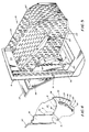
- Figure 5 is a perspective view of a vend chute for use in the vending machine of the present invention.
- the automatic vending machine of the present invention is configured in the form of a chest, whose lid 1, after opening a lock 2, can be folded upwards on hinge brackets 3.
- a cover plate 4 is disposed in the lid 1 and is provided with a coin slot 5.
- a condenser 7 of a cooling unit is mounted externally on the back wall of the automatic vending machine.
- the compressor 8 of this unit is located adjacent the condenser 7.
- the automatic vending machine chest has a front wall 9 and a door 10.
- the front wall 9 In the front wall 9 are inset three cradles 11, 12 and 13. To these are attached placards indicating the various product varieties.
- a coin return opening 14 is provided below the door 10 . This lies roughly underneath the coin slot 5.
- a cooler compartment 15 Behind the door 10 is a space containing a coin control unit with a coin tester and coin changer, and a coin collector box.
- the cooler compartment 15 is thermally insulated on all sides.
- On the inside of the back wall 6 is an evaporator 18 of the cooling unit, and on the floor of the cooling compartment 15 is a drip pan 19 integrally molded with an air foil AF and an evaporator melt layer tray DT.
- a bearing plate 20 is attached to the inside of front wall 9.
- a serpentine basket 21 is arranged, in which are configured alongside each other three chutes 22 operatively associated with the three cradles 11, 12 and 13.
- Each chute has a rearward-slanting upper shelf 23 and a frontward-slanting bottom shelf 24.
- At the back is a passageway 25 provided with a width corresponding to the diameter of the cans D1 to D14.
- the cans D2 to D5 lie in a single tier. However, a double tier of cans may be loaded thereon by pivoting the upper shelf 23 about hinge pin 28 to provide access to the bottom shelf 24.
- the cans D7 to D14 lie in a double tier.
- a rear wall 26 of the chute 22 is provided with a curved portion 27.
- the upper shelf 23 is manually pivotable upwards around a hinge pin 28.
- the shelves 23 and 24 and the rear wall 26, as well as the sidewalls of the chutes 22, are fabricated out of perforated sheet metal. In this way, the cooling circulation in cooler compartment 15 is virtually unimpeded.
- a mechanical support bracket 29 is attached to bearing plate 20.
- the bracket has hinge brackets 30 for a hinge rod 31, on which the three cradles 11, 12 and 13 are installed.
- the mechanical support bracket 29 is provided with further hinge brackets 32 in the vicinity of each of the cradles 11, 12 and 13.
- a sold-out locking lever 34 which is loaded by a spring 35, is fitted on lug 33 of mechanical support bracket 29 in the vicinity of each of the cradles 11, 12 and 13.
- the sold-out locking lever 34 has a switch arm 36 for the actuation of sold-out switches S1, S2 and S3 below the respective cradles.
- the cradles 11, 12 and 13 are mounted so as to pivot on hinge rod 31.
- the cradle is shown in Figure 3 in its closed position by continuous lines and in the open position by broken lines.
- the cradle 11, 12 and 13 has a pull plate 37 attached to an isolating component 38.
- the pickup base plate 40 turns into a roll-on surface 41 through an obtuse angle.
- a support curve 42 Above the roll-on surface 41 in the chute 22 is located a package stop 43.
- the details of the cradle structure are fully disclosed in U.S. Patent 4,235,351 to Kolbl, et al., issued November 25, 1980.
- the pickup base plate 40 is provided with a slot 40' for the sold-out locking lever 34.
- A can lying on the pickup base plate 40, while cradles 11, 12 and 13 are in the closed position, pivots sold-out locking lever 34 against the pressure of spring 35 in the manner shown by the broken lines in Figure 3.
- the sold-out locking lever 34 then actuates the corresponding sold-out switches S1, S2 and S3. If cradles 11, 12 and 13 have no can lying on pickup base plate 40, spring 35 then pulls sold-out locking lever 34 in such a way that a tongue 44 formed in it engages a slot 40' so that the cradles 11, 12 and 13 can no longer be swung out and the corresponding sold-out switches S1, S2 and S3 are no longer actuated.
- This position of the sold-out locking lever 34 is illustrated in Figure 3 by continuous lines. Under each cradle 11, 12 and 13, and located in front wall 9, is an indicator lamp H1, H2 and H3. These light up if the sold-out locking lever 34 does not actuate the switches S1, S2 and S3, and thus if the corresponding chute 22 is empty.
- a tension spring 45 which is attached to support plate 20, acts on each cradle 11, 12 and 13.
- the tension spring 45 pulls the cradles 11, 12 and 13 from their open position into their closed position.
- FIG. 3 also illustrates the operation of the convection refrigeration system of the present invention.
- Air within the product compartment 15 is chilled by the evaporator 18 mounted at the top, rear of the compartment between the top and bottom walls.
- the chilled air tends to drop, creating convective air flow.
- an air foil AF is provided as an integrally-molded part with the condensate drip pan 19 and an evaporator melt layer (defrost) pan DT.
- Defrost tray DT has a drain tube T in fluid communicatin therewith, which extends through the rear wall of compartment 15. Water flows out of tray DT through tube T to a condensate tray CT.
- the hot gas tube HG from compressor 8 extends through tray CT to evaporate water therein to the atmosphere.
- air foil AF is such that together with the underside of bottom shelf 24, a funnel-shaped channel F is formed which focuses and concentrates the flow of chilled air toward cradles 11, 12, 13, rather than permitting the air to stagnate in the lower rear corner of the product compartment 15.
- each cradle is provided with a plurality (preferably six) stand-off ribs R to permit air flow under and around the cans.
- the ribs are preferably at least 5mm. high and are spaced about 1/2 inch apart. Ribs R are also shown in elevation in Figure 4.
- the configuration of the refrigeration system of the present invention inclusive of the air foil AF and stand-off ribs R, permits adequate product pull-down and optimum serving temperatures of the next-to-be-vended products in a purely convective refrigeration system without the need for any circulating fans.
Landscapes
- Physics & Mathematics (AREA)
- General Physics & Mathematics (AREA)
- Control Of Vending Devices And Auxiliary Devices For Vending Devices (AREA)
- Devices That Are Associated With Refrigeration Equipment (AREA)
- Vending Machines For Individual Products (AREA)
- Cold Air Circulating Systems And Constructional Details In Refrigerators (AREA)
Abstract
Description
- The present invention relates to a refrigerated, automatic vending machine of a low-capacity, for bottles or cans (See for example US-A-3752 357). More specifically, the present invention relates to a refrigerated, automatic, coin-operated vending machine of a suitable size for installation on a counter or as a wall console.
- Heretofore, coin-operated, automatic vending machines for bottles or cans have generally been designed to include a high storage capacity, to make them suitable for use in large, commercial establishments. Coin-operated vending machines of smaller capacities, for use in small office or low-volume sales locations have been rather simplistic in their design. These small-capacity vending machines have, for the most part, not included some of the sophisticated controls and features present in the high-capacity vending machines because of the high cost of some of these controls. However, a need in the art exists for a small-capacity, coin-operated, automatic vending machine incorporating more sophisticated controls and features than used heretofore, while maintaining a reasonable cost for each vending machine unit.
- Accordingly, it is a primary object of the present invention to provide a low-cost, low-capacity vending machine, suitable for use in low-volume vending environments.
- It is another object of the present invention to provide a low-capacity vending machine, including a plurality of vend cradles for presenting a variety of selectable products to a customer.
- It is still a further object of the present invention to provide an automatic vending machine with a balanced distribution of cooling through the vend chutes and the remainder of the vending machine cabinet.
- It is yet another object of the present invention to provide a coin-operated vending machine of a suitable size to facilitate use on a counter top or mounting on a wall of a building.
- The objects of the present invention are fulfilled by providing a convection refrigeration system for a cylindrical product vending machine comprising: a thermally insulated cooling compartment for housing the cylindrical products in side-by-side vend chutes; evaporator means included within a mechanical refrigeration assembly disposed adjacent to a rear wall of the compartment for chilling air therein; each of said vend chutes including means for storing and feeding the cylindrical products to a discharge opening in a front face of the vending machine including a pair of sidewalls, an upper shelf disposed between said sidewalls sloping downwardly from the front wall of the cooling compartment toward the rear of the cooling compartment; a bottom shelf disposed below said upper shelf between said sidewalls sloping downwardly from the rear of said chute toward the front of said chute adjacent the discharge opening, a bottom surface of said bottom shelf directing chilled air from said evaporator means toward the discharge opening, whereby said cylindrical products roll along a serpentine path defined by said upper and bottom shelves, said path beginning at the front of said upper shelf and terminating at the discharge opening adjacent the front of said bottom shelf; and characterized by air foil means disposed opposite to the bottom surface of said bottom shelf for concentrating and directing chilled air toward said discharge opening.
- The objects of the present invention and the attendant advantages thereof will become more readily apparent by reference to the accompanying drawings wherein:
- Figure 1 is an elevational view of the automatic vending machine of the present invention;
- Figure 2 is a top plan view of the automatic vending machine of Figure 1;
- Figure 3 is a section taken along line A-A of Figures 1 and 2, illustrating the cooler compartment of the automatic vending machine and one of a plurality of vend chutes and associated cradle mechanisms;
- Figure 4 is a sectional view of a cradle for use in the vending machine of the present invention illustrating stand-off ribs for enhanced product cooling; and
- Figure 5 is a perspective view of a vend chute for use in the vending machine of the present invention.
- Referring to Figs. 1 and 2, the automatic vending machine of the present invention is configured in the form of a chest, whose lid 1, after opening a
lock 2, can be folded upwards onhinge brackets 3. Acover plate 4 is disposed in the lid 1 and is provided with acoin slot 5. - Externally on the back wall of the automatic vending machine, a condenser 7 of a cooling unit is mounted. The
compressor 8 of this unit is located adjacent the condenser 7. - The automatic vending machine chest has a
front wall 9 and adoor 10. In thefront wall 9 are inset threecradles coin return opening 14 is provided. This lies roughly underneath thecoin slot 5. - Referring to Figure 3, behind the
front wall 9 is acooler compartment 15. Behind thedoor 10 is a space containing a coin control unit with a coin tester and coin changer, and a coin collector box. - The
cooler compartment 15 is thermally insulated on all sides. On the inside of the back wall 6 is anevaporator 18 of the cooling unit, and on the floor of thecooling compartment 15 is adrip pan 19 integrally molded with an air foil AF and an evaporator melt layer tray DT. Referring further to Figure 3 and Figure 5, abearing plate 20 is attached to the inside offront wall 9. On this, aserpentine basket 21 is arranged, in which are configured alongside each other threechutes 22 operatively associated with the threecradles upper shelf 23 and a frontward-slanting bottom shelf 24. At the back is apassageway 25 provided with a width corresponding to the diameter of the cans D1 to D14. Onbottom shelf 24, the cans D2 to D5 lie in a single tier. However, a double tier of cans may be loaded thereon by pivoting theupper shelf 23 abouthinge pin 28 to provide access to thebottom shelf 24. On theupper shelf 23, the cans D7 to D14 lie in a double tier. In order to guide the cans of the upper tier to thepassageway 25, arear wall 26 of thechute 22 is provided with acurved portion 27. - The
upper shelf 23 is manually pivotable upwards around ahinge pin 28. Theshelves rear wall 26, as well as the sidewalls of thechutes 22, are fabricated out of perforated sheet metal. In this way, the cooling circulation incooler compartment 15 is virtually unimpeded. - A
mechanical support bracket 29 is attached tobearing plate 20. The bracket hashinge brackets 30 for ahinge rod 31, on which the threecradles mechanical support bracket 29 is provided withfurther hinge brackets 32 in the vicinity of each of thecradles locking lever 34, which is loaded by aspring 35, is fitted onlug 33 ofmechanical support bracket 29 in the vicinity of each of thecradles locking lever 34 has aswitch arm 36 for the actuation of sold-out switches S1, S2 and S3 below the respective cradles. - The
cradles hinge rod 31. The cradle is shown in Figure 3 in its closed position by continuous lines and in the open position by broken lines. Externally, thecradle pull plate 37 attached to anisolating component 38. The side of this, turned away from thepull plate 37, forms aninside surface piece 39, to which apickup base plate 40 is attached by an obtuse angle. Thepickup base plate 40 turns into a roll-onsurface 41 through an obtuse angle. To this is attached asupport curve 42. Above the roll-onsurface 41 in thechute 22 is located apackage stop 43. The details of the cradle structure are fully disclosed in U.S. Patent 4,235,351 to Kolbl, et al., issued November 25, 1980. - The
pickup base plate 40 is provided with a slot 40' for the sold-outlocking lever 34. A can lying on thepickup base plate 40, while cradles 11, 12 and 13 are in the closed position, pivots sold-outlocking lever 34 against the pressure ofspring 35 in the manner shown by the broken lines in Figure 3. The sold-outlocking lever 34 then actuates the corresponding sold-out switches S1, S2 and S3. If cradles 11, 12 and 13 have no can lying onpickup base plate 40,spring 35 then pulls sold-outlocking lever 34 in such a way that atongue 44 formed in it engages a slot 40' so that thecradles locking lever 34 is illustrated in Figure 3 by continuous lines. Under eachcradle front wall 9, is an indicator lamp H1, H2 and H3. These light up if the sold-outlocking lever 34 does not actuate the switches S1, S2 and S3, and thus if thecorresponding chute 22 is empty. - A
tension spring 45, which is attached to supportplate 20, acts on eachcradle tension spring 45 pulls thecradles - The operation of the
cradles - Figure 3 also illustrates the operation of the convection refrigeration system of the present invention. Air within the
product compartment 15 is chilled by theevaporator 18 mounted at the top, rear of the compartment between the top and bottom walls. The chilled air tends to drop, creating convective air flow. In order to concentrate this chilled air flow toward the next-to-be-vended products incradles condensate drip pan 19 and an evaporator melt layer (defrost) pan DT. - Defrost tray DT has a drain tube T in fluid communicatin therewith, which extends through the rear wall of
compartment 15. Water flows out of tray DT through tube T to a condensate tray CT. The hot gas tube HG fromcompressor 8 extends through tray CT to evaporate water therein to the atmosphere. - The shape of air foil AF is such that together with the underside of
bottom shelf 24, a funnel-shaped channel F is formed which focuses and concentrates the flow of chilled air towardcradles product compartment 15. - To further increase the cooling efficiency of the next-to-be-vended products in the cradles, each cradle is provided with a plurality (preferably six) stand-off ribs R to permit air flow under and around the cans. The ribs are preferably at least 5mm. high and are spaced about 1/2 inch apart. Ribs R are also shown in elevation in Figure 4.
- The configuration of the refrigeration system of the present invention, inclusive of the air foil AF and stand-off ribs R, permits adequate product pull-down and optimum serving temperatures of the next-to-be-vended products in a purely convective refrigeration system without the need for any circulating fans.
Claims (6)
- A convection refrigeration system for a cylindrical product vending machine comprising:
a thermally-insulated cooling compartment (15) for housing the cylindrical products (D1-D14) on side-by-side vend chutes (22);
evaporator means (18) included within a mechanical refrigeration assembly disposed adjacent to a rear wall (6) of the compartment for chilling air therein;
each of said vend chutes including means for storing and feeding the cylindrical products to a discharge opening in a front of the vending machine including,
a pair of sidewalls;
an upper shelf (23) disposed between said sidewalls sloping downwardly from the front wall of the cooling compartment toward the rear of the cooling compartment;
a bottom shelf (24) disposed below said upper shelf between said sidewalls sloping downwardly from the rear of said chute toward the front of said chute adjacent the discharge opening, a bottom surface of said bottom shelf (24) directing chilled air from said evaporator (18) means toward the discharge opening, whereby said cylindrical products roll along a serpentine path (21) defined by said upper and bottom shelves (23,24) said path beginning at the front of said upper shelf (23) and terminating at the discharge opening adjacent the front of said bottom shelf (24) and characterized by air foil means (AF) disposed opposite to the bottom surface of said bottom shelf (24) for concentrating and directing chilled air toward said discharge opening. - The system of claim 1, further including a vend cradle (11,12,13) in each discharge opening having a support surface for the next-to-be-vended cylindrical product (D1)in the vend chute (22), said surface having stand-off rib means (R) thereon to space the next-to-be-vended product therefrom, and permit chilled air to flow under and around said product.
- The system according to claim 1, wherein said sidewalls and shelves are perforated to permit the free flow of air and fluids therethrough.
- The system of claim 1, wherein said air foil means (AF) includes a substantially flat surface disposed opposite to the bottom surface of said bottom shelf (24) which slopes downwardly from the rear wall (6) of said compartment toward the front walls (9) thereof and there is further provided a drip-tray (19) adjacent the front wall (9) of the compartment contiguous to said air foil (AF) to receive condensation which runs down the flat surface of the air foil.
- The system of claim 1, further including a defrost tray (DT) for said evaporator (18) means disposed below the evaporator means adjacent the compartment rear wall (6), a drain tube (T) extending from said defrost tray through the rear wall of the compartment, a condensation tray (CT) for collecting water flowing from the drain tube (T) and a hot gas tube (HG) from a compressor(8) in the mechanical refrigeration assembly passing through the condensation tray (CT) for evaporating water therein.
- The system of claim 5, wherein said drip tray, air foil means (AF) and defrost tray (DT) are integrally formed from the same material.
Priority Applications (1)
| Application Number | Priority Date | Filing Date | Title |
|---|---|---|---|
| AT86111131T ATE61137T1 (en) | 1985-08-13 | 1986-08-12 | REFRIGERATION SYSTEM FOR A COUNTERTOP OR WALL HANGED VENDING MACHINE. |
Applications Claiming Priority (2)
| Application Number | Priority Date | Filing Date | Title |
|---|---|---|---|
| US06/765,106 US4676074A (en) | 1984-06-21 | 1985-08-13 | Refrigeration system for a counter-top or wall-mounted vending machine |
| US765106 | 1985-08-13 |
Publications (3)
| Publication Number | Publication Date |
|---|---|
| EP0212544A2 EP0212544A2 (en) | 1987-03-04 |
| EP0212544A3 EP0212544A3 (en) | 1987-08-05 |
| EP0212544B1 true EP0212544B1 (en) | 1991-02-27 |
Family
ID=25072665
Family Applications (1)
| Application Number | Title | Priority Date | Filing Date |
|---|---|---|---|
| EP86111131A Expired - Lifetime EP0212544B1 (en) | 1985-08-13 | 1986-08-12 | Refrigeration system for a counter-top or wall-mounted vending machine |
Country Status (11)
| Country | Link |
|---|---|
| US (1) | US4676074A (en) |
| EP (1) | EP0212544B1 (en) |
| JP (1) | JPS6290795A (en) |
| KR (1) | KR900000227B1 (en) |
| AT (1) | ATE61137T1 (en) |
| AU (1) | AU591154B2 (en) |
| CA (1) | CA1264114A (en) |
| DE (1) | DE3677666D1 (en) |
| ES (1) | ES2001210A6 (en) |
| GR (1) | GR862111B (en) |
| ZA (1) | ZA865942B (en) |
Families Citing this family (40)
| Publication number | Priority date | Publication date | Assignee | Title |
|---|---|---|---|---|
| US4783967A (en) * | 1986-10-16 | 1988-11-15 | Portion Control Systems, Inc. | Dispenser with temperature control |
| EP0287390A3 (en) * | 1987-04-16 | 1990-01-17 | Sanden Corporation | Vending machine with temperature control |
| DE3817853A1 (en) * | 1988-05-26 | 1989-11-30 | Honebein Horst | GOODS MAGAZINE |
| JPH028988A (en) * | 1988-06-28 | 1990-01-12 | Matsushita Refrig Co Ltd | Product output port for automatic vending machine |
| IT1236942B (en) * | 1989-10-13 | 1993-05-07 | AUTOMATIC DRINK DISPENSER. | |
| IT1236941B (en) * | 1989-10-13 | 1993-05-07 | AUTOMATIC DRINK DISPENSING MACHINE. | |
| US4977754A (en) * | 1990-05-01 | 1990-12-18 | Specialty Equipment Companies, Inc. | Next-to-be-purchased cold beverage merchandiser |
| US5201191A (en) * | 1991-09-06 | 1993-04-13 | Leggett & Platt, Inc. | Refrigerated merchandiser |
| US5247798A (en) * | 1993-01-19 | 1993-09-28 | Elwood H. Carpenter | Portable refrigerator |
| US5799822A (en) * | 1994-04-21 | 1998-09-01 | Krh Thermal Systems | Vending machine including multiple failure control devices |
| US5372103A (en) * | 1994-04-25 | 1994-12-13 | Caterpillar Inc. | Method of mounting a ceramic valve guide assembly |
| AUPM897094A0 (en) * | 1994-10-21 | 1994-11-17 | Deeley, Stephanie Tamsin | Dispensing apparatus |
| US5671604A (en) * | 1996-01-22 | 1997-09-30 | The Coca-Cola Company | Apparatus for icing a package |
| US6234345B1 (en) | 1999-03-03 | 2001-05-22 | The Coca-Cola Company | Transportation vending machine |
| USD436133S1 (en) | 1999-03-04 | 2001-01-09 | The Coca-Cola Company | Transportation cooler-dispenser face |
| US6173582B1 (en) * | 1999-04-16 | 2001-01-16 | Sta-Kul, L.L.C. | Self-dispensing portable cooler |
| USD432788S (en) * | 1999-06-18 | 2000-10-31 | Payne Christian S | Portable beverage container holder and dispenser |
| GB2361233B (en) * | 2000-04-15 | 2004-12-22 | Maxim Design Group Ltd | A display unit |
| NO20003636A (en) | 2000-07-14 | 2001-11-26 | Zopa As | Method and device for cooling products in a transport system |
| US6381966B1 (en) * | 2001-04-02 | 2002-05-07 | Kincy L. Barrow | Refrigerated container dispenser and method |
| US7275498B2 (en) * | 2001-12-06 | 2007-10-02 | The Proctor 'gamble Company | Flowable solids dispensing apparatus and method of use |
| US6668578B2 (en) * | 2002-03-04 | 2003-12-30 | David Coakley | Glass chilling method and apparatus |
| WO2003093742A1 (en) * | 2002-05-06 | 2003-11-13 | Faber Walter G | Beverage dispenser |
| US6685051B2 (en) | 2002-05-21 | 2004-02-03 | Hussman Corporation | Cooling apparatus and releasing system for beverages in containers |
| ITPN20020036A1 (en) * | 2002-05-27 | 2003-11-27 | Necta Vending Solutions Spa | ANTI-THEFT DEVICE FOR AUTOMATIC DISTRIBUTORS OF PACKAGED PRODUCTS. |
| US7024882B2 (en) * | 2003-09-16 | 2006-04-11 | William Scott Carmichael | Cooler with ordered refilling |
| US20050150900A1 (en) * | 2004-01-09 | 2005-07-14 | American Trim, L.L.C. | Beverage can dispenser |
| US7377123B2 (en) * | 2004-01-09 | 2008-05-27 | American Trim, L.L.C. | Refrigerator with through-the-door beverage can dispenser |
| US7418311B1 (en) * | 2005-05-23 | 2008-08-26 | Golf Concessions Llc | Portable dispensing device for refreshments and sundries |
| US7810350B2 (en) * | 2007-03-22 | 2010-10-12 | Shelton Andrew C | Beverage dispensing cooler |
| US8261940B2 (en) * | 2007-04-06 | 2012-09-11 | The Coca-Cola Company | Vending dispenser assemblies for beverage dispensers |
| USD625125S1 (en) | 2009-02-13 | 2010-10-12 | Pepsico, Inc. | Cooler |
| WO2012054491A2 (en) * | 2010-10-19 | 2012-04-26 | Deborah Lowry | Gravity-fed dispenser |
| PL2649597T3 (en) | 2010-12-08 | 2019-03-29 | Apex Industrial Technologies Llc | Direct access dispensing system |
| US20130240553A1 (en) * | 2012-03-15 | 2013-09-19 | Steven W. Burton | Product Dispenser and System with Pivoting Container Support Deck |
| GB2530327A (en) * | 2014-09-22 | 2016-03-23 | 42 Technology Ltd | Heat transfer apparatus |
| US10195096B1 (en) * | 2017-11-14 | 2019-02-05 | Juli Sickler | Feminine hygiene product dispenser |
| IT201800002330A1 (en) * | 2018-02-02 | 2019-08-02 | Giuseppe Biffarella | PRODUCT DISTRIBUTING MACHINE |
| CN111563998B (en) * | 2020-05-20 | 2024-08-02 | 江苏毅迈电器科技有限公司 | Automatic shipment machine of cold-stored easy open can |
| US11654376B2 (en) * | 2021-06-15 | 2023-05-23 | Lovevery, Inc. | Count and slide ring chute |
Family Cites Families (12)
| Publication number | Priority date | Publication date | Assignee | Title |
|---|---|---|---|---|
| US1951239A (en) * | 1931-12-29 | 1934-03-13 | John J Friel | Article dispenser |
| US2790526A (en) * | 1950-11-24 | 1957-04-30 | Schenley Ind Inc | Can vending machine |
| DE1096658B (en) * | 1953-07-16 | 1961-01-05 | Telefonbau & Normalzeit Gmbh | Compartment self-seller with cooling device |
| US3087649A (en) * | 1958-05-02 | 1963-04-30 | Rowe Mfg Company Inc | Refrigerated-sandwich merchandising machine |
| US3110417A (en) * | 1959-02-17 | 1963-11-12 | Wilmer J Wingate | Automatic can vending machine |
| US3237810A (en) * | 1964-04-27 | 1966-03-01 | Magi Pak Corp | Liquid comestible dispensing cabinet with cooling means |
| US3272300A (en) * | 1965-06-29 | 1966-09-13 | King Seeley Thermos Co | Ice vending machine |
| US3752357A (en) * | 1970-12-23 | 1973-08-14 | Rowe International Inc | High capacity, small size vendor for cans |
| JPS53133096A (en) * | 1977-04-26 | 1978-11-20 | Toshiba Denki Kigu Kk | Automatic chilled goods vending device |
| US4485937A (en) * | 1982-04-22 | 1984-12-04 | Adams Morgan A | Can dispensing apparatus |
| US4576272A (en) * | 1984-06-21 | 1986-03-18 | The Coca-Cola Company | Counter-top or wall-mounted vending machine |
| US4729480A (en) * | 1986-08-18 | 1988-03-08 | The Coca-Cola Company | Expanded capacity vend basket for a vending machine |
-
1985
- 1985-08-13 US US06/765,106 patent/US4676074A/en not_active Expired - Lifetime
-
1986
- 1986-08-06 AU AU60925/86A patent/AU591154B2/en not_active Ceased
- 1986-08-07 ZA ZA865942A patent/ZA865942B/en unknown
- 1986-08-08 CA CA000515566A patent/CA1264114A/en not_active Expired - Lifetime
- 1986-08-11 GR GR862111A patent/GR862111B/en unknown
- 1986-08-12 JP JP61187968A patent/JPS6290795A/en active Granted
- 1986-08-12 AT AT86111131T patent/ATE61137T1/en not_active IP Right Cessation
- 1986-08-12 KR KR1019860006637A patent/KR900000227B1/en not_active Expired
- 1986-08-12 DE DE8686111131T patent/DE3677666D1/en not_active Expired - Lifetime
- 1986-08-12 EP EP86111131A patent/EP0212544B1/en not_active Expired - Lifetime
- 1986-08-12 ES ES8601035A patent/ES2001210A6/en not_active Expired
Also Published As
| Publication number | Publication date |
|---|---|
| ATE61137T1 (en) | 1991-03-15 |
| KR900000227B1 (en) | 1990-01-23 |
| DE3677666D1 (en) | 1991-04-04 |
| US4676074A (en) | 1987-06-30 |
| ZA865942B (en) | 1987-04-29 |
| JPS6290795A (en) | 1987-04-25 |
| AU591154B2 (en) | 1989-11-30 |
| AU6092586A (en) | 1987-02-19 |
| GR862111B (en) | 1986-11-11 |
| EP0212544A2 (en) | 1987-03-04 |
| CA1264114A (en) | 1990-01-02 |
| KR870002534A (en) | 1987-03-31 |
| JPH0156437B2 (en) | 1989-11-30 |
| EP0212544A3 (en) | 1987-08-05 |
| ES2001210A6 (en) | 1988-05-01 |
Similar Documents
| Publication | Publication Date | Title |
|---|---|---|
| US4676074A (en) | Refrigeration system for a counter-top or wall-mounted vending machine | |
| EP0165617A2 (en) | Counter-top of wall-mounted vending machine | |
| US4823984A (en) | Container storage and dispensing apparatus and vending machine for dispensing refrigerated, unrefrigerated and/or heated foods | |
| AU675799B2 (en) | Apparatus to convert a refrigerated vendor to a refrigerateddisplay case | |
| US4416122A (en) | Unitary removable refrigeration system and cooler | |
| US5678421A (en) | Refrigeration unit for cold space merchandiser | |
| US2371845A (en) | Vending apparatus | |
| CN101160078A (en) | Modular Cooling Box | |
| US4513879A (en) | Hot/cold food dispensing machine | |
| US4482078A (en) | Hot/cold food dispensing machine | |
| EP0490693A2 (en) | Dispenser | |
| US2641112A (en) | Refrigerator-cabinet defrosting | |
| KR20210022702A (en) | Heat storage material unit and vending machine equipped with this heat storage material unit | |
| US2644319A (en) | Device for maintaining different temperatures in refrigerators | |
| CN1998030A (en) | manual dispenser | |
| KR200162568Y1 (en) | Assay rack for vending machine of plastic bottle drink | |
| JP2679250B2 (en) | vending machine | |
| KR200333720Y1 (en) | Vending machine for ice | |
| KR100530536B1 (en) | Vending machine for ice | |
| CA1091049A (en) | Dual temperature merchandiser | |
| JPH03109695A (en) | Automatic vending machine | |
| KR19990025021U (en) | Condensate Warning System of Vending Machine | |
| JPH03201182A (en) | Autamatic vending machine | |
| JPH0950561A (en) | vending machine | |
| JPH07230573A (en) | vending machine |
Legal Events
| Date | Code | Title | Description |
|---|---|---|---|
| PUAI | Public reference made under article 153(3) epc to a published international application that has entered the european phase |
Free format text: ORIGINAL CODE: 0009012 |
|
| AK | Designated contracting states |
Kind code of ref document: A2 Designated state(s): AT BE CH DE FR GB IT LI LU NL SE |
|
| PUAL | Search report despatched |
Free format text: ORIGINAL CODE: 0009013 |
|
| AK | Designated contracting states |
Kind code of ref document: A3 Designated state(s): AT BE CH DE FR GB IT LI LU NL SE |
|
| 17P | Request for examination filed |
Effective date: 19871020 |
|
| 17Q | First examination report despatched |
Effective date: 19890712 |
|
| RIN1 | Information on inventor provided before grant (corrected) |
Inventor name: BAUMGARTNER, GUNTER Inventor name: WILLIFORD, HUGH Inventor name: GRESS, JOSEF Inventor name: MEHLAN, BERND Inventor name: MORGAN, ANNIS RAY, JR. |
|
| 17Q | First examination report despatched |
Effective date: 19891218 |
|
| GRAA | (expected) grant |
Free format text: ORIGINAL CODE: 0009210 |
|
| AK | Designated contracting states |
Kind code of ref document: B1 Designated state(s): AT BE CH DE FR GB IT LI LU NL SE |
|
| REF | Corresponds to: |
Ref document number: 61137 Country of ref document: AT Date of ref document: 19910315 Kind code of ref document: T |
|
| ITF | It: translation for a ep patent filed | ||
| REF | Corresponds to: |
Ref document number: 3677666 Country of ref document: DE Date of ref document: 19910404 |
|
| ET | Fr: translation filed | ||
| PLBE | No opposition filed within time limit |
Free format text: ORIGINAL CODE: 0009261 |
|
| STAA | Information on the status of an ep patent application or granted ep patent |
Free format text: STATUS: NO OPPOSITION FILED WITHIN TIME LIMIT |
|
| 26N | No opposition filed | ||
| PGFP | Annual fee paid to national office [announced via postgrant information from national office to epo] |
Ref country code: SE Payment date: 19920617 Year of fee payment: 7 |
|
| PGFP | Annual fee paid to national office [announced via postgrant information from national office to epo] |
Ref country code: AT Payment date: 19920622 Year of fee payment: 7 |
|
| PGFP | Annual fee paid to national office [announced via postgrant information from national office to epo] |
Ref country code: CH Payment date: 19920624 Year of fee payment: 7 |
|
| PGFP | Annual fee paid to national office [announced via postgrant information from national office to epo] |
Ref country code: BE Payment date: 19920706 Year of fee payment: 7 |
|
| PGFP | Annual fee paid to national office [announced via postgrant information from national office to epo] |
Ref country code: FR Payment date: 19920716 Year of fee payment: 7 |
|
| PGFP | Annual fee paid to national office [announced via postgrant information from national office to epo] |
Ref country code: LU Payment date: 19920724 Year of fee payment: 7 |
|
| PGFP | Annual fee paid to national office [announced via postgrant information from national office to epo] |
Ref country code: NL Payment date: 19920831 Year of fee payment: 7 |
|
| PGFP | Annual fee paid to national office [announced via postgrant information from national office to epo] |
Ref country code: GB Payment date: 19921009 Year of fee payment: 7 |
|
| EPTA | Lu: last paid annual fee | ||
| PG25 | Lapsed in a contracting state [announced via postgrant information from national office to epo] |
Ref country code: LU Free format text: LAPSE BECAUSE OF NON-PAYMENT OF DUE FEES Effective date: 19930812 Ref country code: GB Effective date: 19930812 Ref country code: AT Effective date: 19930812 |
|
| PG25 | Lapsed in a contracting state [announced via postgrant information from national office to epo] |
Ref country code: SE Effective date: 19930813 |
|
| PG25 | Lapsed in a contracting state [announced via postgrant information from national office to epo] |
Ref country code: LI Effective date: 19930831 Ref country code: CH Effective date: 19930831 Ref country code: BE Effective date: 19930831 |
|
| BERE | Be: lapsed |
Owner name: THE COCA-COLA CY Effective date: 19930831 |
|
| PG25 | Lapsed in a contracting state [announced via postgrant information from national office to epo] |
Ref country code: NL Effective date: 19940301 |
|
| GBPC | Gb: european patent ceased through non-payment of renewal fee |
Effective date: 19930812 |
|
| NLV4 | Nl: lapsed or anulled due to non-payment of the annual fee | ||
| PG25 | Lapsed in a contracting state [announced via postgrant information from national office to epo] |
Ref country code: FR Effective date: 19940429 |
|
| REG | Reference to a national code |
Ref country code: CH Ref legal event code: PL |
|
| REG | Reference to a national code |
Ref country code: FR Ref legal event code: ST |
|
| EUG | Se: european patent has lapsed |
Ref document number: 86111131.8 Effective date: 19940310 |
|
| PGFP | Annual fee paid to national office [announced via postgrant information from national office to epo] |
Ref country code: DE Payment date: 19990722 Year of fee payment: 14 |
|
| PG25 | Lapsed in a contracting state [announced via postgrant information from national office to epo] |
Ref country code: DE Free format text: LAPSE BECAUSE OF NON-PAYMENT OF DUE FEES Effective date: 20010501 |
|
| PG25 | Lapsed in a contracting state [announced via postgrant information from national office to epo] |
Ref country code: IT Free format text: LAPSE BECAUSE OF NON-PAYMENT OF DUE FEES;WARNING: LAPSES OF ITALIAN PATENTS WITH EFFECTIVE DATE BEFORE 2007 MAY HAVE OCCURRED AT ANY TIME BEFORE 2007. THE CORRECT EFFECTIVE DATE MAY BE DIFFERENT FROM THE ONE RECORDED. Effective date: 20050812 |