EP0211162A2 - Inhaltsverzeichnissystem für verteilte Datenbank mit Kontrollblöcken für sequentielle und parallele Abfrage - Google Patents
Inhaltsverzeichnissystem für verteilte Datenbank mit Kontrollblöcken für sequentielle und parallele Abfrage Download PDFInfo
- Publication number
- EP0211162A2 EP0211162A2 EP86106716A EP86106716A EP0211162A2 EP 0211162 A2 EP0211162 A2 EP 0211162A2 EP 86106716 A EP86106716 A EP 86106716A EP 86106716 A EP86106716 A EP 86106716A EP 0211162 A2 EP0211162 A2 EP 0211162A2
- Authority
- EP
- European Patent Office
- Prior art keywords
- query
- directory
- dsu
- control block
- accordance
- Prior art date
- Legal status (The legal status is an assumption and is not a legal conclusion. Google has not performed a legal analysis and makes no representation as to the accuracy of the status listed.)
- Withdrawn
Links
Images


Classifications
-
- G—PHYSICS
- G06—COMPUTING OR CALCULATING; COUNTING
- G06F—ELECTRIC DIGITAL DATA PROCESSING
- G06F16/00—Information retrieval; Database structures therefor; File system structures therefor
- G06F16/20—Information retrieval; Database structures therefor; File system structures therefor of structured data, e.g. relational data
- G06F16/24—Querying
- G06F16/245—Query processing
- G06F16/2453—Query optimisation
- G06F16/24532—Query optimisation of parallel queries
-
- G—PHYSICS
- G06—COMPUTING OR CALCULATING; COUNTING
- G06F—ELECTRIC DIGITAL DATA PROCESSING
- G06F16/00—Information retrieval; Database structures therefor; File system structures therefor
- G06F16/20—Information retrieval; Database structures therefor; File system structures therefor of structured data, e.g. relational data
- G06F16/25—Integrating or interfacing systems involving database management systems
Definitions
- the present invention is directed to systems for implementing the sequential and parallel propagation of queries in a data base directory by means of two sets of tables. These tables can either be user-defined or automatically created based on user-defined algorithms.
- directory means a table of names and corresponding items of data. Data in a directory is locational or directive in nature, e.g.
- the user of a directory knows the definition of the object references by a name, but needs the specific data value(s), e.g. phone number, in order to perform a specific activity.
- Distributed database management systems offer users the ability to distribute data and workload among multiple processing sites. Ideally, a distributed database management system should support growth while preserving local administrative autonomy and control of access to locally stored data. At the same time, the distributed database should provide its users with a single system image such that, although the data is distributed among several sites, the data distribution is transparent to the users who express their database accesses as though the data is at one place.
- the distributed database management system architecture should preserve local control and function when accessing local database objects.
- the fact that a site participates in the distributed database should not reduce that site's ability to perform local actions on local data by requiring the participation of other sites.
- data access availability should be a function only of the availability of the site(s) storing that data objects. The failure of one site should not impact sites which do not reference database objects stored (or controlled) by the failed site.
- U.S. Patent 4,468,728 discloses data structure and a search method for a database management system in which the data structure is arranged in a plurality of search trees.
- the initial search tree and an initial subset of trees are maintained in a main fast access memory, while the remaining trees are kept in mass memory.
- An input search parameter is partitioned into a plurality of subparameters, one for each search tree. The subparameters are used to search a tree in each level of the data structure until the location of a terminating file is determined.
- API Applications Interface
- DSU Directory Service Unit
- DSU Directory Service Interface
- DSS Directory Service System
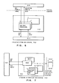
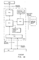
- Fig. 12 illustrates the different interfaces or protocol boundaries between the DSU shown in the dotted exclosure and other portions of the system. These boundaries include a user protocol boundary shown at the top of the figure, a data access protocol boundary at the right side of the figure representing the interface between the DSU and the database, and a communications protocol boundary illustrated at the bottom of the figure.
- the present structure and method is based on a distribution scheme where an instance of directory service may include on or more DSUs. Each DSU may perform one or more directory functions depending upon the product implementation.
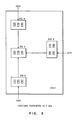
- the directory service system shown in Figure 1 is an installation of directory functions in a network of interconnected system.
- DSS provides the architectural directory services for the user at the API protocol boundary.
- the participating systems (products) in a DSS operate coherently under the architected rules such as data distribution schemes, naming schemes, search/update algorithms, error recovery, synchronization and the like.
- a DSS is comprised of a collection of directory service units distributed throughout the interconnected system network as shown in Figure 2.
- a DSU represents the directory service component of a system product implementing directory service functions. Although multiple DSUs may exist in the same system (product) for different applications, it is the intent that a single DSU can support many applications programs to eliminate duplication.
- a DSU is composed of a set of functional components called directory service processes (DSP) to provide the subsetting basis for implementation by products.
- DSP directory service processes
- every DSU in the system implement all DSPs.
- a work-station may implement only some of the functions and obtain full directory service through interaction with a larger system product.
- a DSU may contain all four DSPs or some of the DSPs as necessary to meet the functional needs of each product.
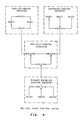
- Figure 3 shows an example of implementation options by products in a simple network.
- DSU A and DSU D represent the work-station which performs the query on an as needed basis and discards the results of the query without retaining it in the storage. This type of product may not have to implement P(D).
- DSU C represents another type of work-station which retains the results of a query in its local directory. This type of product needs to implement P(D).
- DSU B represents the file server which acts merely as a data repository to maintain the master directory for the network. This type of product may not have to implement P(U).
- the origin or source DSU receives a directory request from the user and originates the DSI request.
- the request is propagated through the intermediate DSUs as necessary to reach the target DSU which can service the request.
- a directory is a database that stores mappings from name to information related to name.
- the directory data base is a set of directories which contain information of a similar type. There is more than one member in the set if the directory data base is distributed across participating DSUs.
- the directory data base and all members which comprise it are named via a directory type ID (Directory Identifier). For example, a directory database with directory type_ID TELEPHONE may contain name to telephone number mappings.
- a single DSU may maintain directories of different directory type_ID's, but for any given type_ID, a DSU may contain at most one directory.
- each DSU In the local directory system, there is no master directory in the system and each DSU maintains its local directory data. When a DSU cannot satisfy the directory request from its local directory, it queries all other directories in the system until the requested data has been located.
- each DSU in the system has a master directory.
- the advantage of this system is its fast query response time.
- the disadvantage of this system is the cost of storing master directory information at each DSU, as well as the communication cost for updating all these directories.
- a single level (primitive) distribution scheme described above that is, centralized, localized and distributed
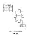
- hybrid systems combining various primitive distribution schemes in a hierarchical manner, as illustrated in Figure 4 may be attractive.
- the hybrid multiple level design can offer both types of performance improvements over a single level design.
- the hybrid directory system is logically divided in subsystems, or regions, made up of any number of distributed directory services. Each subsystem uses different (primitive) directory distribution schemes to fit into its regional environment. The hierarchical relationships between subsystems are independent of the actual topology of the physical network.
- a directory service can define the functional relationship among the DSUs distributed in the network due to the following aspects:
- the relationship provides a method of organizing the DSUs distributed in the network to allow the definition of simple and efficient protocols for the propagation of DSI commands such as query/update.
- the relationship can be used to constrain the set of DSUs to which a particular DSU can send a DSI command for query/update.
- the relationship is used to control how to distribute the directories, per directory type, among DSUs and how to maintain the respective directory.
- the relationship of a particular set of DSUs might reflect the organization structure of the enterprise owning the network, even though the network topology does not.
- the lines joining the DSUs in Figure 2 indicate the communication paths. Communication between DSUs may be accomplished through the use of any one of several different transport mechanisms. For example, DSUs may communicate with each other by running as a set of transaction models using IBM's System Network Architecture (SNA) or equivalent level of transport facilities. In this case, the lines represent sessions and may not resemble in any way the physical topology of the network. The only assumption that the directory service structure makes about the nature of the transport mechanism is that it provides guaranteed error-free delivery of data from source to destination.
- SNA System Network Architecture
- the user makes a directory function request by way of the API verbs to one of the DSUs.
- the requested DSU interacts with other remote DSUs, and then provides the appropriate response to the user.
- DSP DIRECTORY SERVICE PROCESS
- each DSP may be implemented either in programming or by a microprocessor.
- the P(U) basically manages the protocol boundary to service the end user request. Only P(U) interfaces with the API, thus shielding other DSPs from the end user. At the request of the end user, P(U) parses the received verbs and sends the directory request to P(F) for the information/ response. When it receives the information/response from P(F), it returns it to user to satisfy the original API verb.
- P(U) consists of a set of API verb processors, each of which has two components (API send processor and API receive processor).
- the API send processor is to parse the API verbs and its associated parameters from the user and construct the DSI request encoding to be sent to P(F) for specific directory tasks as requested in the API verbs.
- the API receive processor is to decode the received DSI replies and present the information/data (carried in the reply) to the user protocol boundary according to the defined API rules.
- Directory Function Service P(F)
- the P(F) performs the essence of distributed directory functions such as search/update algorithms and naming algorithm.
- P(F) is knowledgeable of the existence of distributed directories and name database (if any), and it provides a focal point for maintaining currency among them in the system.
- the P(F) is responsible for providing the information response satisfying the request from P(U).
- P(F) maintains/ manages the directory operation control block to be used by the directory algorithm facilities.
- the control block contains the algorithm control information such as affinity lists.
- P(F) uses this information to determine the best way to get information and respond to the requests from P(U).
- P(F) interacts with other remote P(F)s as necessary to locate the target P(F) (that is, the P(F) directly linked to the P(D) which can access requested directory data).
- the target P(F) obtains the directory data from the D(P), and sends it to the source P(F) (that is, the P(F) that originally received a request from P(U)).
- the source P(F) passes the directory data to the P(U) that originated the request.
- P(F) is the bridge form of service interacting with both P(U) and P(D), as well as P(N).
- P(F) consists of a set of DSI command processors, each of which has two components (DSI request processor and DSI reply processor) to process the received requests and replies respectively.
- the format of the input to the P(F) should preserve the DSI command construct regardless of whether the command is received from the P(U) or the remote P(F)s through the communication network.
- the DSI request processor the DSI processes the DSI requests received from either P(U) or remote DSUs. It uses the directory algorithm facilities such as the query/update propagation algorithm and the name assignment algorithm as appropriate. The directory algorithms determine the target DSU which can provide the requested information. If the receiving DSU is determined to be the target DSU, the DSI request processor fetches the requested information by way of P(D) and sends the DSI reply carrying that information to the origin DSU. Otherwise, the DSI request processor passes the received request to the other DSU as the algorithm determines, based on the affinity lists of the operation control block.
- the DSI reply processor processes the DSI replies which carry the information requested by the DSI requests. If the receiving DSU is the origin DSU (which originated the DSI request), the DSI reply processor passes it to the local P(U). Otherwise, it sends the received DSI reply toward the origin DSU.
- the P(D) manages the directory data access protocol boundary to access and maintain the directory data. Only P(D) has knowledge of the structure of the directory contents by way of the directory descriptors specified by the users, thus shielding other DSP's from the directory data structures.
- the P(D) receives the directory data request (query, update and so on) from P(F), performs the appropriate operation on the directory data by way of the data access protocol boundary and responds as appropriate to the P(F). It is the responsibility of P(F) to locate the target P(D) (that is, the P(D) maintaining the requested directory data) before sending a request to that P(D).
- the P(D) consists of two processors, Read and Write.
- the read processor services the DSI requests (for example, query), from P(F), which requires reading the directory data through the data access protocol boundary. It reads the requested directory data according to the directory descriptors and returns the retrieved data by way of the appropriate DSI reply to P(F).
- the write processor services the DSI requests (for example, update), from P(F), which requires writing the directory data through the data access protocol boundary. It performs the directory data update as requested, according to the directory descriptors, and returns the results, if necessary, via the appropriate DSI reply.
- the P(N) provides the ability to send and receive the DSI commands between DSUs. It interfaces with the transport mechanism used for DSU-DSU communication, thus shielding other DSP's from the networking function. P(N) controls the network protocol boundaries to achieve the P(F) to P(F) conversation between remote DSUs.
- the content of DSI request/replies are basically transparent to P(N), and the function of P(N) is merely to deliver the DSI requests/replies to the remote P(F)'s through the network. Also, the P(N) does not determine where to send queries or updates. This is determined by the propagation algorithm in the P(F).
- the P(N) consists of two processors, send and receive.
- the send processor is to control the sending of data in a DSU-DSU communication.
- the receive processor is to receive data from the DSU-DSU communication.
- the functions of these processors have direct dependencies on the protocol boundary of the network used for DSU-DSU communication.
- the directory structure describes the specific functions of P(N) required to use the DSU-DSU transport mechanisms.
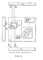
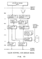
- a DSS can be viewed as a collection of an arbitrary number of P(U)s, P(F)s, P(D)s and P(N)s ( Figure 9).
- a DSU must contain at least a P(F) and a P(N), although the levels of complexity of the functions to be performed vary depending on the roles of the DSU within a DSS.
- DSI commands are used as the message units to carry information from one DSP to another. There are two types of DSI commands, DSI request and DSI reply. The DSI request is used to carry the specific request information to the target DSP, and the DSI reply to carry the information/response to the origin DSP.
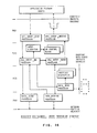
- Figure 10 shows the DSI request flows among DSPs.
- the possible flows are: (1) P(U) - P(F), (2) P(F) - P(F) by way of P(N)s, and (3) P(F) - P(D).
- Figure 11 shows the DSI reply flows among DSPs.
- the possible flows are: (1) P(D) - P(F), (2) P(F) - P(F), and (3) P(F) - P(U).
- the present system defines one protocol boundary for its users and uses three different protocol boundaries to formally describe the system structure.
- a DSU provides the protocol boundary for the user to send the directory requests to DSU and receive the directory information/response from DSU.
- DSU uses the protocol boundary of a communication network to communicate with another DSU in another system.
- Another protocol boundary is used by DSU to control accesses to and read and write the data in a directory data model.
- the functions of these verbs may be implemented in a product unique manner.
- the invention employs a Directory Operation Control Block whose structure and function may be described as follows :
- the directory operation control block contains information which controls the directory system functions performed on behalf of the user.
- This component includes search (query) algorithm control information, and internal tables which define the relationship of this member user directory with other members (at other DSUs) within a particular directory database.
- the directory operation control block (Fig. 15) supports directory system services such as automatic search and automatic maintenance to the user.
- This control block is associated with a particular member of the directory database, and the information contained therein is location-dependent.
- This control block is usually initialized by way of directory system generation parameters, although changes to internal operation of the directory system for this member may occur dynamically through the protocol boundary.
- the directory operation control block contains the affinity list, search algorithm control field, integrity parameters field, and access control field, which can be described as follows.
- the affinity list describes the logical relationship between this member and other members of a particular directory database.
- the affinity list data values describe whether other directory database members are superiors, peers, or subordinates to this member, as will be described more in detail below. How directory data is distributed, and logically configured, can therefore be derived from affinity list data values.
- affinity list design enables a reconfiguration of user data (say, from a centralized to a distributed configuration) by subsequent changes to affinity list data values.
- This field supports various user options of the automatic name resolution function. Such options may include action to be taken by the DSU upon determining a "not found” condition at this member, such as report an "error”, continue searching using internal search algorithms, or return a data value to the user.
- the P-tables at the various DSUs define how each DSU interact with one other DSUs in performing queries.
- Each DSU in the network contains and P-tables for every directory type for which it may perform undirected queries, and the P-table in a DSU contains the identities of some of the other DSUs in the network. It must be possible to establish a communication path with any DSU that appears in a P-table.
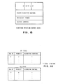
- the P-table consists of two parts, a query P-table (QP-table) and an update P-table (UP-table).
- the QP-table defines the DSUs to which queries are sent.
- the structure of the tables is shown in Fig. 16. In addition to containing the identities of the DSUs, these tables define the order in which the DSUs are queried, by specifying a numeric parameter or priority associated with each DSU. The DSU with the highest priority is sent the query message first. DSUs with equal priority receive the messages in parallel. As Fig. 16 also depicts, there is an extra algorithm control field associated with each DSU entry, whose function will be described below.
- each P-table may be created in several different ways. They may be linked directly to the way in which data is distributed through the system, something which may be specified in the form of an affinity table. Alternatively, the P-tables may be defined directly at SYSTEM GENERATION time and remain unchanged through the entire directory operation, or they may be updated dynamically. They may also be dynamically created during operation or through other mechanisms such as queries to a "directory of directories" or through input from the network routing function.
- the protocol boundary in the system may permit only indirect access to the P-tables.
- the indirection is in that the user does not specify the actual entries in the P-tables, but, instead, specifies the way in which he wants data distributed through the network using certain data distribution primitives. These notions are then translated automatically into entries in P-tables.
- the user may define some data distribution relationships between the DSUs in the network. This section describes the relationships, how they are used to set up a directory service system, and how these relationships then get translated into P-table entries.
- the relationship is depicted pictorially by a directed arc from A to B, as shown in Fig. 17.
- A being the SUB
- B being the SUP.
- the relationship is established by specifying at A that B is a SUP of A and by specifying that A is a SUB of B.
- This relationship implies that under "normal" conditions a communication path from the SUB to the SUP through the transport mechanism exists.
- X is the directory type ID for which this relationship has been defined, then B's directory type ID is a superset of A's directory of the same type ID.
- This relationship is depicted pictorially by an undirected arc between the PEERs, as shown in Fig. 19.
- the relationship is established by specifying at A that B is a PEER of A and by specifying at B that A is a PEER of B.
- This relationship implies that the PEERs can communicate with each other through the transport mechanism and that the user would like them to communicate directly in order to perform directory functions. It does not imply any relationship in terms of data distribution.
- queries are exchanged between PEERs.
- Fig. 20 shows the translation.
- This relationship is depicted pictorially by a bidirectional arc between the DSUs as shown in Fig. 21.
- the relationship is set-up by specifying at A that B is a REPLICATE of A and by specifying at B that A is a REPLICATE of B.
- This relationship implies that the DSUs can communicate with each other through the transport mechanism.
- it is equivalent to two SUP-SUB relationships; that is, B is a superset of A and A is a superset of B.
- the translation to P-table entries is designed to preserve the replication by propagating updates between the DSU's.
- Fig. 18 depicts the translation.
- Figs. 23-26 illustrate that the definition of relationships between the DSUs in a network determines the data distribution. It will be noted that the relationships define a network over which queries are normally propagated. This network is usually a sub-network of the network formed by defining all possible communication paths. In other words, there may be communication paths available between DSU's which are not normally used in query propagation.
- both SUPs and PEERs are entered into the table.
- parallel propagation queries it is not always the case that parallel propagation is desirable.
- sequential propagation may be preferable as it may result in less bandwidth being used in query propagation.
- two basic methods, the parallel and the sequential are provided for constructing P-tables.
- the choice of parallel or sequential can be controlled at the time of system definition.
- the parallel approach is very similar to that used in the construction of the UP-tables. All SUP entries are given equal priority and all PEER entries are given equal priority. The priority of the SUPs, however, is higher than the priority of the PEERs (that is, a smaller numerical value). For reasons that will become apparent when the algorithms are described, the SUPs are assigned a negative number as priority.
- Fig. 28 shows an example.
- the determination of whether parallel or sequential propagation is used is usually made at create-configuration time or automatically by means of a predefined user algorithm. It is important that all the DSU's participating in a given query use the same mode of propagation. Thus, it is not permitted for the originating node to propagate a query in a sequential fashion and for intermediary nodes to relay that query in parallel fashion. In order to ensure this, the query messages propagated in the network contain a bit which indicates whether the DSU that initiated the query used sequential or parallel propagation.
- Intermediary nodes use the method of propagation indicated in the query message, thereby ignoring the priorities in the QP-table, and creating a new set of priorities if the query message specifies a different mode of propagation than the mode for which their QP-tables are set up.
- the relationships of the DSUs in the network for a given directory type ID should satisfy certain rules. These rules are important in order to maintain internal consistency of the P-table in a given DSU, as well as in the relationship between P-tables in different DSUs.
- the rules are as follows:
- B is PEER(A)
- D cannot be SUP(A) or REPLICATE(A).
- B is SUP(A)
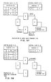
- the query message sent between the DSUs contains all the information from the initial inquiry and, in addition, the identification of the DSU that originated the propagation of the query (the source DSU), and a correlation number which is generated by the source DSU.
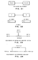
- Fig. 30 shows a typical query message.
- Any response message contains the information generated in response to the query and, importantly, also includes the identification of the DSU that was the source of the query and the correlation number contained in the query.
- Fig. 31 shows a typical query response message. The combination of source DSU identification and correlation number is used by the various DSU's in the network to uniquely identify that query and to correlate responses to the query with the query itself.
- the DSU identities are required to be unique. In order for the combined DSU identity plus correlation number to be unique, it is necessary for the source DSU to ensure that it uses a correlation number only if it is certain that no instance of any previous query message that it may have generated with the same correlation number remains in the network. A practical method of achieving this is to use as a correlation number a time-stamp or a constantly incremented sequence number, taking care to ensure that the size of the correlation number field and therefore, the time between wrapping of the number is large.
- the propagation of query messages is guided by the P-tables for that directory type at each DSU.
- the algorithm is essentially a message driven distributed version of depth-first search.
- the same code runs in all the DSUs, including the source of the query and the DSU that finally satisfies the request. It is sequential in the sense that there is only one message related to a query in the network at any one time.
- the message could be either the query itself or a response to the query.
- the receipt of a message can be interpreted as obtaining control of the query propagation, and in sequential propagation only a single DSU has control at any one time.
- the source DSU selects a DSU from the QP-table and sends the query message to it. It then waits until it receives the response from that DSU before proceeding with searching the rest of the entries in its QP-table.
- the DSU that receives the query performs in a similar fashion. It selects a DSU from its QP-table and sends it a query. If this DSU has already been searched, it will respond immediately. Otherwise, it will in turn propagate the query further.
- a DSU receives a response to a query, it forwards it to the source of the query if it is a positive response. Otherwise, if the response is negative, it scans its P-table to see if there are any entries with which it has not exchanged a query and response. If so, it sends that DSU the query, and if not, it responds negatively to the source of the query.
- a data structure is built by each DSU that receives and propagates the query.
- This data structure is created from information in the QP-table and in the query message itself.
- the query control block contains a pointer to the API or another DSU to indicate the origin of the first copy of that particular query.
- the query control block contains the correlation number of the query and the ID of the source DSU. It also contains the identities of the DSUs to which queries may be propagated.
- the control block contains two extra fields. The first extra field corresponds to messages sent out and the second field corresponds to messages received and these will be labeled as OUT and IN, respectively.
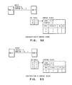
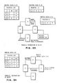
- Fig 28 and Fig. 29 show examples of the construction of query control blocks.
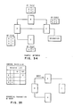
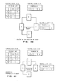
- a network consisting of four DSUs A, B, C and D connected as shown in Fig. 34. All connected DSUs are defined to be PEERs and sequential propagation is chosen, resulting in QP-tables at the various DSUs as shown in Fig. 34.
- the next step is to propagate messages in the network.
- DSU A selects the entry (or entries) in its QP-table with the smallest priority number. In this case this entry is DSU B. It sends DSU B a query message, marks the OUT field corresponding to DSU B, and waits until it gets a response.
- Fig. 35 describes the state of the system at this point.
- B Upon receiving the query from A, B first checks its local directory. Upon not finding the required information, it creates the same type of control block as A did, marking it with the label A.10 and entering, as pointer, DSU A. As before, to create the body of the control block it copies the QP-table and adds two extra fields. However, it removes the origin of the query, A, from the control block as it is not necessary to propagate queries back to the source. It then sends a query to C, the DSU with the highest priority in the control block.
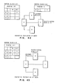
- Figure 36 describes the state of the system at this point. C receives the query, finds the information in its local directory, and sends back a response to B.
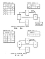
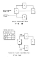
- Figure 37 shows the system at this state.
- DSU A receives the response, recognizes that it is a response to a query for which it has a control block in existence, and forwards the response, as indicated by the pointer in the control block, to DSU A. It then deletes the control block.
- Figure 38 depicts the system at this state.
- DSU A receives the response and, as indicated by the control block for the query, forwards the response to the API and deletes the control block as shown in Figure 39.
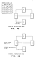
- Parallel propagation is a message driven distributed version of breadth first search.
- the control block that is set up is identical to that which is set up in sequential propagation.
- queries are sent to many DSUs simultaneously.
- the algorithm must run to completion by searching every possible DSU.
- the parallel algorithm because of its parallelism, is considerably faster in response time than the sequential algorithm. However, it does take up more bandwidth than the sequential algorithm on average, though in the worst case both algorithms use equal bandwidth.
- the QP-table divides the QP-table into two parts, one part containing all DSUs with negative priorities (the SUPs) and one part containing all the DSUs with positive priorities (the PEERs). It first initiates a query to the SUPs by using the above algorithm and assuming that the SUP portion of the QP-table comprises the entire QP-table. When this query completes, it query the PEERs by using the above algorithm and assuming that the PEER portion of the QP-table comprise the entire QP-table.
Landscapes
- Engineering & Computer Science (AREA)
- Theoretical Computer Science (AREA)
- Databases & Information Systems (AREA)
- Data Mining & Analysis (AREA)
- Physics & Mathematics (AREA)
- General Engineering & Computer Science (AREA)
- General Physics & Mathematics (AREA)
- Computational Linguistics (AREA)
- Information Retrieval, Db Structures And Fs Structures Therefor (AREA)
Applications Claiming Priority (2)
| Application Number | Priority Date | Filing Date | Title |
|---|---|---|---|
| US74355485A | 1985-06-11 | 1985-06-11 | |
| US743554 | 1985-06-11 |
Publications (2)
| Publication Number | Publication Date |
|---|---|
| EP0211162A2 true EP0211162A2 (de) | 1987-02-25 |
| EP0211162A3 EP0211162A3 (de) | 1990-08-22 |
Family
ID=24989232
Family Applications (1)
| Application Number | Title | Priority Date | Filing Date |
|---|---|---|---|
| EP86106716A Withdrawn EP0211162A3 (de) | 1985-06-11 | 1986-05-16 | Inhaltsverzeichnissystem für verteilte Datenbank mit Kontrollblöcken für sequentielle und parallele Abfrage |
Country Status (3)
| Country | Link |
|---|---|
| EP (1) | EP0211162A3 (de) |
| JP (1) | JPS61283945A (de) |
| CA (1) | CA1252905A (de) |
Cited By (2)
| Publication number | Priority date | Publication date | Assignee | Title |
|---|---|---|---|---|
| US5257366A (en) * | 1990-03-27 | 1993-10-26 | International Business Machines Corporation | Query language execution on heterogeneous database servers using a bind-file bridge between application and database languages |
| GB2277176B (en) * | 1993-04-14 | 1997-10-01 | Fujitsu Ltd | Information retrieval system with hierarchical data management |
-
1986
- 1986-04-23 CA CA000507379A patent/CA1252905A/en not_active Expired
- 1986-05-09 JP JP61105074A patent/JPS61283945A/ja active Pending
- 1986-05-16 EP EP86106716A patent/EP0211162A3/de not_active Withdrawn
Non-Patent Citations (3)
| Title |
|---|
| 2ND INT. CONF. ON DISTRIBUTED COMPUTING SYSTEMS, Paris, 8th - 10th April 1981, pages 31-40, IEEE, New York, US; B. LINDSAY: "Object naming and catalog management for a distributed database manager" * |
| 5TH INT. CONF. ON VERY LARGE DATA BASES, Rio de Janeiro, 3rd - 5th October 1979, pages 340-350, IEEE, New York, US; H. BREITWIESER et al.: "Transaction and catalog management of the distributed file management system disco" * |
| JOURNAL OF TELECOMMUNICATION NETWORKS, vol. 2, no. 3, 1983, pages 249-269, Computer Science Press, Inc., Rockville, Maryland, US; V.D. GLIGOR et al.: "Distributed database management systems: An architectural perspective" * |
Cited By (2)
| Publication number | Priority date | Publication date | Assignee | Title |
|---|---|---|---|---|
| US5257366A (en) * | 1990-03-27 | 1993-10-26 | International Business Machines Corporation | Query language execution on heterogeneous database servers using a bind-file bridge between application and database languages |
| GB2277176B (en) * | 1993-04-14 | 1997-10-01 | Fujitsu Ltd | Information retrieval system with hierarchical data management |
Also Published As
| Publication number | Publication date |
|---|---|
| CA1252905A (en) | 1989-04-18 |
| EP0211162A3 (de) | 1990-08-22 |
| JPS61283945A (ja) | 1986-12-13 |
Similar Documents
| Publication | Publication Date | Title |
|---|---|---|
| JP5090450B2 (ja) | 階層に編成され、ネットワークを介してリンクされた複数のノードに保管された複製データを更新するための方法、プログラム、およびコンピュータ可読媒体 | |
| EP0213276A2 (de) | Dynamische Datenbankinhaltsverzeichnisänderung | |
| StoicaЃ et al. | Chord: A scalable peer-to-peer lookup service for internet applications | |
| US6725261B1 (en) | Method, system and program products for automatically configuring clusters of a computing environment | |
| KR100505265B1 (ko) | 의미 정보 네트워크 | |
| US7103664B1 (en) | Method, system and program products for ordering lists of service addresses to provide load balancing of a clustered environment | |
| CN102035886B (zh) | 联盟基础结构内的一致性 | |
| US6925490B1 (en) | Method, system and program products for controlling system traffic of a clustered computing environment | |
| US7035931B1 (en) | Volume location service for a distributed file system | |
| US8549180B2 (en) | Optimizing access to federation infrastructure-based resources | |
| US20080263207A1 (en) | Method and apparatus for providing dynamic group management for distributed interactive applications | |
| EP0520749B1 (de) | Verfahren und Gerät für Netzrechnersystemgruppenverwaltung | |
| JP2000165449A (ja) | 情報ル―ティング方法 | |
| JP2002041488A (ja) | クラスタ化コンピューティング環境を管理するための方法、システム、およびプログラム製品 | |
| Paluska et al. | Footloose: A case for physical eventual consistency and selective conflict resolution | |
| US6725218B1 (en) | Computerized database system and method | |
| Akbarinia et al. | Data management in the APPA system | |
| EP0213277A2 (de) | Propagationssystem für Netzwerkabfragen durch verteilte Datenbank | |
| CN117440003A (zh) | 一种无中心的分布式存储方法及系统 | |
| van der Linden | The ANSA naming model | |
| CN102316154A (zh) | 优化对基于联盟基础结构的资源的访问 | |
| EP0211162A2 (de) | Inhaltsverzeichnissystem für verteilte Datenbank mit Kontrollblöcken für sequentielle und parallele Abfrage | |
| Yeo et al. | A taxonomy of issues in name systems design and implementation | |
| EP0204993A2 (de) | Hybrides Datenverteilungssystem für Inhaltsverzeichnis | |
| Ordille | Descriptive Name Services for Large Internets |
Legal Events
| Date | Code | Title | Description |
|---|---|---|---|
| PUAI | Public reference made under article 153(3) epc to a published international application that has entered the european phase |
Free format text: ORIGINAL CODE: 0009012 |
|
| AK | Designated contracting states |
Kind code of ref document: A2 Designated state(s): DE FR GB IT |
|
| 17P | Request for examination filed |
Effective date: 19870422 |
|
| PUAL | Search report despatched |
Free format text: ORIGINAL CODE: 0009013 |
|
| AK | Designated contracting states |
Kind code of ref document: A3 Designated state(s): DE FR GB IT |
|
| 17Q | First examination report despatched |
Effective date: 19920217 |
|
| STAA | Information on the status of an ep patent application or granted ep patent |
Free format text: STATUS: THE APPLICATION IS DEEMED TO BE WITHDRAWN |
|
| 18D | Application deemed to be withdrawn |
Effective date: 19920828 |
|
| RIN1 | Information on inventor provided before grant (corrected) |
Inventor name: SINGH, HARINDER S. Inventor name: GOPAL, INDER Inventor name: WON, JOHA HYUN Inventor name: BARTOCCI, FRANCIS DENNIS |