EP0211156B1 - Valve mechanism lubrication system for an overhead valve engine - Google Patents
Valve mechanism lubrication system for an overhead valve engine Download PDFInfo
- Publication number
- EP0211156B1 EP0211156B1 EP86106424A EP86106424A EP0211156B1 EP 0211156 B1 EP0211156 B1 EP 0211156B1 EP 86106424 A EP86106424 A EP 86106424A EP 86106424 A EP86106424 A EP 86106424A EP 0211156 B1 EP0211156 B1 EP 0211156B1
- Authority
- EP
- European Patent Office
- Prior art keywords
- oil
- breather chamber
- valve
- rocker box
- breather
- Prior art date
- Legal status (The legal status is an assumption and is not a legal conclusion. Google has not performed a legal analysis and makes no representation as to the accuracy of the status listed.)
- Expired
Links
- 230000007246 mechanism Effects 0.000 title claims description 35
- 238000005461 lubrication Methods 0.000 title claims description 22
- 239000003595 mist Substances 0.000 claims description 27
- 239000007788 liquid Substances 0.000 claims description 15
- 238000002485 combustion reaction Methods 0.000 claims description 5
- 238000013022 venting Methods 0.000 claims description 4
- 239000003921 oil Substances 0.000 description 65
- 230000000717 retained effect Effects 0.000 description 4
- 230000001050 lubricating effect Effects 0.000 description 3
- 239000010687 lubricating oil Substances 0.000 description 2
- 230000002000 scavenging effect Effects 0.000 description 2
- 238000010276 construction Methods 0.000 description 1
- 238000001816 cooling Methods 0.000 description 1
- 239000000446 fuel Substances 0.000 description 1
- 238000005086 pumping Methods 0.000 description 1
- 239000011435 rock Substances 0.000 description 1
Images


Classifications
-
- F—MECHANICAL ENGINEERING; LIGHTING; HEATING; WEAPONS; BLASTING
- F01—MACHINES OR ENGINES IN GENERAL; ENGINE PLANTS IN GENERAL; STEAM ENGINES
- F01M—LUBRICATING OF MACHINES OR ENGINES IN GENERAL; LUBRICATING INTERNAL COMBUSTION ENGINES; CRANKCASE VENTILATING
- F01M11/00—Component parts, details or accessories, not provided for in, or of interest apart from, groups F01M1/00 - F01M9/00
- F01M11/02—Arrangements of lubricant conduits
-
- F—MECHANICAL ENGINEERING; LIGHTING; HEATING; WEAPONS; BLASTING
- F01—MACHINES OR ENGINES IN GENERAL; ENGINE PLANTS IN GENERAL; STEAM ENGINES
- F01M—LUBRICATING OF MACHINES OR ENGINES IN GENERAL; LUBRICATING INTERNAL COMBUSTION ENGINES; CRANKCASE VENTILATING
- F01M13/00—Crankcase ventilating or breathing
-
- F—MECHANICAL ENGINEERING; LIGHTING; HEATING; WEAPONS; BLASTING
- F02—COMBUSTION ENGINES; HOT-GAS OR COMBUSTION-PRODUCT ENGINE PLANTS
- F02B—INTERNAL-COMBUSTION PISTON ENGINES; COMBUSTION ENGINES IN GENERAL
- F02B75/00—Other engines
- F02B75/005—Other engines having horizontal cylinders
-
- F—MECHANICAL ENGINEERING; LIGHTING; HEATING; WEAPONS; BLASTING
- F02—COMBUSTION ENGINES; HOT-GAS OR COMBUSTION-PRODUCT ENGINE PLANTS
- F02B—INTERNAL-COMBUSTION PISTON ENGINES; COMBUSTION ENGINES IN GENERAL
- F02B75/00—Other engines
- F02B75/007—Other engines having vertical crankshafts
-
- F—MECHANICAL ENGINEERING; LIGHTING; HEATING; WEAPONS; BLASTING
- F01—MACHINES OR ENGINES IN GENERAL; ENGINE PLANTS IN GENERAL; STEAM ENGINES
- F01M—LUBRICATING OF MACHINES OR ENGINES IN GENERAL; LUBRICATING INTERNAL COMBUSTION ENGINES; CRANKCASE VENTILATING
- F01M13/00—Crankcase ventilating or breathing
- F01M13/0011—Breather valves
-
- F—MECHANICAL ENGINEERING; LIGHTING; HEATING; WEAPONS; BLASTING
- F02—COMBUSTION ENGINES; HOT-GAS OR COMBUSTION-PRODUCT ENGINE PLANTS
- F02B—INTERNAL-COMBUSTION PISTON ENGINES; COMBUSTION ENGINES IN GENERAL
- F02B75/00—Other engines
- F02B75/02—Engines characterised by their cycles, e.g. six-stroke
- F02B2075/022—Engines characterised by their cycles, e.g. six-stroke having less than six strokes per cycle
- F02B2075/027—Engines characterised by their cycles, e.g. six-stroke having less than six strokes per cycle four
-
- F—MECHANICAL ENGINEERING; LIGHTING; HEATING; WEAPONS; BLASTING
- F02—COMBUSTION ENGINES; HOT-GAS OR COMBUSTION-PRODUCT ENGINE PLANTS
- F02B—INTERNAL-COMBUSTION PISTON ENGINES; COMBUSTION ENGINES IN GENERAL
- F02B2275/00—Other engines, components or details, not provided for in other groups of this subclass
- F02B2275/34—Lateral camshaft position
-
- F—MECHANICAL ENGINEERING; LIGHTING; HEATING; WEAPONS; BLASTING
- F02—COMBUSTION ENGINES; HOT-GAS OR COMBUSTION-PRODUCT ENGINE PLANTS
- F02F—CYLINDERS, PISTONS OR CASINGS, FOR COMBUSTION ENGINES; ARRANGEMENTS OF SEALINGS IN COMBUSTION ENGINES
- F02F7/00—Casings, e.g. crankcases
- F02F7/006—Camshaft or pushrod housings
Definitions
- This invention relates to a breather induced lubrication system for the upper valve mechanism of an overhead valve, single cylinder, four stroke, internal combustion engine, as per the preamble of claim 1.
- FR-A-1 002 437 discloses a lubrication system as per the said type.
- oil vapors rise from the crankcase through a rocker arm passage into a rocker box, from which the vapors then return to a breather, and from there to a settling capacity reservoir, and then the oil returns to the crankcase by way of an oil orifice.
- US-A-2 366 701 discloses a system, whereby a baffle maintains a pool of oil, on one side thereof, which overflows to the other side and returns through a tube to the engine. This does not perform satisfactorily due to several problems.
- oil will not drain from the rocker box to the oil sump thus causing oil to build up in the rocker box.
- As enough oil builds up the breather will pump oil from the rocker box to the exterior of the engine. This is unsatisfactory because of oil spillage on and around the engine and the loss of lubricating oil which can result in engine failure due to lack of lubrication.
- US-A-4 470 389 discloses a lubrication system based on a similar principle: the pressure/ vacuum produced in the crankcase by the horizontal piston stroke causes oil mist to move up to the parts to be lubricated and back to the oil sump through the breather.
- US-A-3 456 759 and US-A-1 734 007 describe the use of hollow tubes housing push rods for circulating lubricating oil mist between rocker box and crankcase. Such systems are unsatisfactory, because of the cost of providing the required oil pumping mechanism and furthermore because a separate breather mechanism is required to vent the crankcase.
- valve mechanism lubricating system whereby lubrication is induced by the breather. It is furthermore desired to provide a valve lifter actuation mechanism whereby oil mist in the crankcase is induced by the breather to flow past and thereby lubricate the rocker mechanism, then to be conducted to the breather for venting to the atmosphere, wherein condensed oil is drained back to the oil sump.
- the present invention overcomes the disadvantages of the above described prior art lubrication systems by providing an improved breather induced lubrication system therefor, as per the characterizing features of claim 1.
- the invention in one form thereof, provides an internal combustion engine valve lifter mechanism lubricating system wherein one push rod tube conducts oil mist from the crankcase to the rocker box and a second push rod tube conducts oil mist and condensed liquid oil from the rocker box to a breather chamber.
- the breather chamber is vented through a breather valve mechanism to the atmosphere and is also connected by a drain passage to the oil sump. Liquid oil drains from the breather chamber to the oil sump through the drain passage.
- the present invention in one form thereof, provides a loop circuit from the crankcase to the oil sump whereby oil mist is induced to flow by the breather toward the rocker box through one push rod tube and is then caused to flow over the valve actuating mechanism by means of a baffle which is located in the rocker box. Oil mist and condensed liquid oil are then induced to flow from the rocker box toward the breather chamber through a second push rod tube.
- the breather chamber is vented through a valve mechanism to the atmosphere. Liquid oil collected in the breather chamber will drain back to the oil sump due to the greater pressure in the breather as compared to the low pressure generated in the crankcase.
- valve rocker mechanism is lubricated without the need for additional pumps to pump oil from the sump to the rocker box nor requires a scavenging pump to remove the oil from the rocker box when used in the horizontal cylinder mode with the crankshaft in a vertical position.
- a still further advantage of the present invention is that engines incorporating the lubrication system of the present invention may be oriented in head down attitudes without causing oil to be pumped out of the breather.
- Yet another advantage of the present invention is that it is simple in construction and low in cost yet very effective in lubricating the valve lifter mechanism.
- the invention in one form thereof comprises a lubrication system for the valve actuating mechanism of an internal combustion engine which includes a crankcase, a breather chamber and a rocker box for housing the valve actuating mechanism.
- a first hollow push rod tube which houses a first push rod has one end open to the crankcase and an opposite end open to the rocker box whereby oil mist is conducted from the crankcase to the rocker box for lubrication of the valve actuating mechanism.
- a second hollow push rod tube which houses a second push rod has one end open to the rocker box and an opposite end open to the breather chamber for conducting oil mist and liquid oil from the rocker box to the breather chamber.
- the breather box includes a vent for venting the breather chamber to the atmosphere.
- a drain is provided for draining liquid oil which collects in the breather chamber to the oil sump.
- Yet another object of the present invention is to provide a valve lifter lubrication system which is economical and effective.
- an engine 10 including a crankcase 12 and a cylinder 14.
- the engine includes cooling fins 16 disposed around cylinder 14.
- a valve 18 in cylinder 14 operates in a conventional manner to selectively permit entry of fuel into cylinder 14 as is conventional.
- Another valve (not shown) is provided for exhausting combustion products from cylinder 14.
- a valve actuating mechanism is shown including a tappet 20 which is operated by a cam and a cam shaft (not shown) in a conventional manner.
- the tapet operates on a push rod 22 which is reciprocably housed in push rod tube 24.
- two valve actuating mechanisms are provided for the inlet and exhaust valves 18 respectively.
- a valve rocker mechanism 26 is housed in a rocker box 27 comprised of a rocker box base 28 and a rocker box cover 29.
- the rocker box cover 29 is retained on the rocker box base 28 by means of two fasteners 31 which engage with two threaded shafts 30 received in threaded apertures 32 in bushings 37 of crankcase 12. Fasteners 31 are threaded into apertures in the ends of shafts 30.
- Rockers 38 are retained on shafts 30 by means of washers 34 and nuts 35 whereby rockers 38 can rock or pivot in response to actuation of push rods 2 by tappets 20.
- valve stem bushings 48 operate as bearings for stems 44 and as guides for valve springs 46.
- rocker box base 28 includes a groove 54 into which a flanged portion of rocker box cover 29 is retained. Additionally a seal 56 is located in groove 54 whereby cover 29 of rocker box 27 is sealingly engaged with base 28 of the rocker box so that no oil mist escapes from rocker box 27 externally of the engine.
- Rocker box 27 also includes a baffle 58, secured to rocker box base 29.
- a plate 60 is supported on bushings 37 and retained in place by nuts 61, two of which are provided, and which engage with threaded shafts 30. Plate 60 includes a pair of upstanding flanges 62 for guiding push rods 22.
- a pair of apertures 64 and 66 are shown in rocker box base 28 on either side of baffle 58 through which push rods 22 extend from push rod tubes 24 into rocker box 27. Additionally, a pair of apertures 68 are shown in bushings 48 through which valve stems 44 of valves 18 extend into rocker box 27.
- push rod tubes 24 are sealed to rocker box 27 by means of O-rings 74 and annular flanges 75. Additionally push rod tubes 24 are sealed to crankcase 12 by means of O-rings 76 and annular flanges 77.
- the upper push rod tube 24, as shown in Fig. 2 is open to the crankcase by means of aperture 78 whereby oil mist can flow from crankcase 12 into upper push rod tube 29 tube as shown by arrows 79.
- Lower push rod tube 24, as shown in Fig. 2 opens into the interior of a breather 82 comprising a breather chamber 84. Oil mist can therefore travel from rocker box 27 to breather chamber 84 as shown by arrows 80.
- Breather 82 also includes a disc valve 86 as best shown in Fig. 1, whereby breather chamber 84 is vented to the atmosphere through disc valve 86 and vent tube 88 as best shown in Figs. 1 and 3. Breather chamber 84 communicates with an oil sump 92 in crankcase 12 by means of a drain passage 90. Breather chamber 88 is closed by means of a breather cover 94.
- the disc valve 86 comprises a check valve whereby the breather chamber is vented to the atmosphere and pressures in crankcase 12 above atmospheric pressure are relieved through breather 82 as shown by arrow 83. However, when the crankcase pressure goes slightly below atmospheric pressure by operation of the piston in cylinder 14, check valve 86 will close off breather chamber 84 thereby preventing a flow of air into breather chamber 84 from the ambient atmosphere.
- the provision of drain passage 90 in crankcase 12 will assist liquid oil, which collects in chamber 84, to drain therefrom and through conduit 90 into oil sump 92 when the crankcase pressure falls below atmospheric pressure, since the pressure in breather chamber 84 is normally at substantially atmospheric pressure.
- Oil drain passage 90 is preferably made rather small whereby a difference of pressure may exist across passage 90 without rapid pressure equalization between chamber 84 and oil sump 92.
- crankcase oil mist will travel out of the crankcase 12 through aperture 78 and through upper push rod tube 24 as shown in Fig. 2 and aperture 64 into rocker box 27.
- the oil mist which enters rocker box 27 will be forced by baffle 58, as best shown in Fig. 4, to flow past the valve actuating mechanism 26 for lubrication thereof as shown by the arrows. Without baffle 58 the oil mist would shortcircuit the valve mechanism 26 and would flow directly from inlet 64 to outlet 66 without contacting mechanism 26. Since rocker mechanism 26 is cooler than the oil mist, some of the oil mist will condense in the rocker box.
Landscapes
- Engineering & Computer Science (AREA)
- Mechanical Engineering (AREA)
- General Engineering & Computer Science (AREA)
- Chemical & Material Sciences (AREA)
- Combustion & Propulsion (AREA)
- Lubrication Details And Ventilation Of Internal Combustion Engines (AREA)
- Lubrication Of Internal Combustion Engines (AREA)
Description
- This invention relates to a breather induced lubrication system for the upper valve mechanism of an overhead valve, single cylinder, four stroke, internal combustion engine, as per the preamble of claim 1.
- FR-A-1 002 437 discloses a lubrication system as per the said type. Thereby, oil vapors rise from the crankcase through a rocker arm passage into a rocker box, from which the vapors then return to a breather, and from there to a settling capacity reservoir, and then the oil returns to the crankcase by way of an oil orifice. There is a baffle in the rocker box for directing the oil mist.
- US-A-2 366 701 discloses a system, whereby a baffle maintains a pool of oil, on one side thereof, which overflows to the other side and returns through a tube to the engine. This does not perform satisfactorily due to several problems. First of all, when the engine is oriented in the head down attitude, oil will not drain from the rocker box to the oil sump thus causing oil to build up in the rocker box. As enough oil builds up the breather will pump oil from the rocker box to the exterior of the engine. This is unsatisfactory because of oil spillage on and around the engine and the loss of lubricating oil which can result in engine failure due to lack of lubrication.
- One solution to the above problems is to use a scavenging pump to remove the liquid oil from the rocker box and thereby prevent the build up of liquid oil therein. However, the provision of such a pump adds to the cost of the engine which is unsatisfactory.
- US-A-4 470 389 discloses a lubrication system based on a similar principle: the pressure/ vacuum produced in the crankcase by the horizontal piston stroke causes oil mist to move up to the parts to be lubricated and back to the oil sump through the breather.
- US-A-3 456 759 and US-A-1 734 007 describe the use of hollow tubes housing push rods for circulating lubricating oil mist between rocker box and crankcase. Such systems are unsatisfactory, because of the cost of providing the required oil pumping mechanism and furthermore because a separate breather mechanism is required to vent the crankcase.
- It is therefore desired to provide a simple, effective valve mechanism lubricating system whereby lubrication is induced by the breather. It is furthermore desired to provide a valve lifter actuation mechanism whereby oil mist in the crankcase is induced by the breather to flow past and thereby lubricate the rocker mechanism, then to be conducted to the breather for venting to the atmosphere, wherein condensed oil is drained back to the oil sump.
- The present invention overcomes the disadvantages of the above described prior art lubrication systems by providing an improved breather induced lubrication system therefor, as per the characterizing features of claim 1.
- The invention, in one form thereof, provides an internal combustion engine valve lifter mechanism lubricating system wherein one push rod tube conducts oil mist from the crankcase to the rocker box and a second push rod tube conducts oil mist and condensed liquid oil from the rocker box to a breather chamber. The breather chamber is vented through a breather valve mechanism to the atmosphere and is also connected by a drain passage to the oil sump. Liquid oil drains from the breather chamber to the oil sump through the drain passage.
- The present invention, in one form thereof, provides a loop circuit from the crankcase to the oil sump whereby oil mist is induced to flow by the breather toward the rocker box through one push rod tube and is then caused to flow over the valve actuating mechanism by means of a baffle which is located in the rocker box. Oil mist and condensed liquid oil are then induced to flow from the rocker box toward the breather chamber through a second push rod tube. The breather chamber is vented through a valve mechanism to the atmosphere. Liquid oil collected in the breather chamber will drain back to the oil sump due to the greater pressure in the breather as compared to the low pressure generated in the crankcase.
- Another advantage of the lubrication system according to the present invention is that the valve rocker mechanism is lubricated without the need for additional pumps to pump oil from the sump to the rocker box nor requires a scavenging pump to remove the oil from the rocker box when used in the horizontal cylinder mode with the crankshaft in a vertical position.
- A still further advantage of the present invention is that engines incorporating the lubrication system of the present invention may be oriented in head down attitudes without causing oil to be pumped out of the breather.
- Yet another advantage of the present invention is that it is simple in construction and low in cost yet very effective in lubricating the valve lifter mechanism.
- The invention, in one form thereof comprises a lubrication system for the valve actuating mechanism of an internal combustion engine which includes a crankcase, a breather chamber and a rocker box for housing the valve actuating mechanism. A first hollow push rod tube which houses a first push rod has one end open to the crankcase and an opposite end open to the rocker box whereby oil mist is conducted from the crankcase to the rocker box for lubrication of the valve actuating mechanism. A second hollow push rod tube which houses a second push rod has one end open to the rocker box and an opposite end open to the breather chamber for conducting oil mist and liquid oil from the rocker box to the breather chamber. The breather box includes a vent for venting the breather chamber to the atmosphere. A drain is provided for draining liquid oil which collects in the breather chamber to the oil sump.
- It is an object of the present invention to provide a valve lifter mechanism lubrication system whereby oil mist is caused to flow from the crankcase in a loop circuit to lubricate the valve lifter mechanism and whereby liquid oil is induced by the breather to drain back from the valve lifter mechanism to the crankcase.
- It is another object of the present invention to provide a breather induced valve lifter mechanism lubrication system whereby an engine incorporating the system and with the breather on top of the rocker cover may be oriented in head down attitude without causing oil to be pumped through the breather out of the engine.
- Yet another object of the present invention is to provide a valve lifter lubrication system which is economical and effective.
- The above mentioned and other features and objects of this invention and the manner of attaining them will become more apparent and the invention itself will be better understood by reference to the following description of an embodiment of the invention taken in conjuction with the accompanying drawings, wherein:
- Fig. 1 is a plan view in cross section of the valve actuation and breather system;
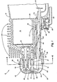
- Fig. 2 is an elevational sectional view of the valve actuation and breather system of Fig 1;
- Fig. 3 is a partially broken away elevational view of the value actuation and breather system of Fig. 11;
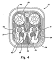
- Fig. 4 is an enlarged sectional end view of the rocker box and valve actuating mechanism taken along line 4-4 of Fig. 1;
- Corresponding reference characters indicate corresponding parts throughout the several views of the drawings.
- The exemplifications set out herein illustrate a preferred embodiment of the invention, in one form thereof, and such exemplifications are not to be construed as limiting the scope of the disclosure or the scope of the invention.
- Referring now to Figs. 1 and 2 an
engine 10 is shown including acrankcase 12 and acylinder 14. The engine includescooling fins 16 disposed aroundcylinder 14. Avalve 18 incylinder 14 operates in a conventional manner to selectively permit entry of fuel intocylinder 14 as is conventional. Another valve (not shown) is provided for exhausting combustion products fromcylinder 14. A valve actuating mechanism is shown including atappet 20 which is operated by a cam and a cam shaft (not shown) in a conventional manner. The tapet operates on apush rod 22 which is reciprocably housed inpush rod tube 24. As best seen in Fig. 2 two valve actuating mechanisms are provided for the inlet andexhaust valves 18 respectively. - A
valve rocker mechanism 26 is housed in arocker box 27 comprised of arocker box base 28 and arocker box cover 29. Therocker box cover 29 is retained on therocker box base 28 by means of twofasteners 31 which engage with two threadedshafts 30 received in threaded apertures 32 inbushings 37 ofcrankcase 12.Fasteners 31 are threaded into apertures in the ends ofshafts 30.Rockers 38 are retained onshafts 30 by means ofwashers 34 andnuts 35 wherebyrockers 38 can rock or pivot in response to actuation of push rods 2 bytappets 20. Therefore aspush rods 22 are actuated bytappets 20, the actuating ends 40 ofpush rods 22 will operate onrockers 38 to causerockers 38 to pivot and thereby actuate valve stems 44 ofvalves 18. Springs 46 are provided forbiasing valves 18 into their normally closed positions. Valvestem bushings 48 operate as bearings forstems 44 and as guides forvalve springs 46. - By referring to Fig. 4 it can be seen that
rocker box base 28 includes agroove 54 into which a flanged portion ofrocker box cover 29 is retained. Additionally aseal 56 is located ingroove 54 wherebycover 29 ofrocker box 27 is sealingly engaged withbase 28 of the rocker box so that no oil mist escapes fromrocker box 27 externally of the engine.Rocker box 27 also includes abaffle 58, secured torocker box base 29. Aplate 60 is supported onbushings 37 and retained in place bynuts 61, two of which are provided, and which engage with threadedshafts 30.Plate 60 includes a pair ofupstanding flanges 62 for guidingpush rods 22. A pair ofapertures rocker box base 28 on either side ofbaffle 58 through whichpush rods 22 extend frompush rod tubes 24 intorocker box 27. Additionally, a pair ofapertures 68 are shown inbushings 48 through which valve stems 44 ofvalves 18 extend intorocker box 27. - Referring again to Figs. 1 and 2, it can be seen that
push rod tubes 24 are sealed torocker box 27 by means of O-rings 74 andannular flanges 75. Additionallypush rod tubes 24 are sealed tocrankcase 12 by means of O-rings 76 andannular flanges 77. The upperpush rod tube 24, as shown in Fig. 2, is open to the crankcase by means ofaperture 78 whereby oil mist can flow fromcrankcase 12 into upperpush rod tube 29 tube as shown byarrows 79. Lowerpush rod tube 24, as shown in Fig. 2, opens into the interior of abreather 82 comprising abreather chamber 84. Oil mist can therefore travel fromrocker box 27 tobreather chamber 84 as shown byarrows 80.Breather 82 also includes adisc valve 86 as best shown in Fig. 1, wherebybreather chamber 84 is vented to the atmosphere throughdisc valve 86 and venttube 88 as best shown in Figs. 1 and 3.Breather chamber 84 communicates with anoil sump 92 incrankcase 12 by means of adrain passage 90.Breather chamber 88 is closed by means of abreather cover 94. - The
disc valve 86 comprises a check valve whereby the breather chamber is vented to the atmosphere and pressures incrankcase 12 above atmospheric pressure are relieved throughbreather 82 as shown byarrow 83. However, when the crankcase pressure goes slightly below atmospheric pressure by operation of the piston incylinder 14,check valve 86 will close offbreather chamber 84 thereby preventing a flow of air intobreather chamber 84 from the ambient atmosphere. The provision ofdrain passage 90 incrankcase 12 will assist liquid oil, which collects inchamber 84, to drain therefrom and throughconduit 90 intooil sump 92 when the crankcase pressure falls below atmospheric pressure, since the pressure inbreather chamber 84 is normally at substantially atmospheric pressure. Liquid oil will therefore be aided in draining throughdrain passage 90 intooil sump 92 as shown byarrows 81.Oil drain passage 90 is preferably made rather small whereby a difference of pressure may exist acrosspassage 90 without rapid pressure equalization betweenchamber 84 andoil sump 92. - In operation, when the engine piston is in its downward stroke in
cylinder 14 and compresses the gas incrankcase 12, crankcase oil mist will travel out of thecrankcase 12 throughaperture 78 and through upperpush rod tube 24 as shown in Fig. 2 andaperture 64 intorocker box 27. The oil mist which entersrocker box 27 will be forced bybaffle 58, as best shown in Fig. 4, to flow past thevalve actuating mechanism 26 for lubrication thereof as shown by the arrows. Withoutbaffle 58 the oil mist would shortcircuit thevalve mechanism 26 and would flow directly frominlet 64 tooutlet 66 without contactingmechanism 26. Sincerocker mechanism 26 is cooler than the oil mist, some of the oil mist will condense in the rocker box. This condensed oil mist will drain through lowerpush rod tube 24 intobreather chamber 84. Additionally, the remaining oil mist inrocker box 27 will travel through lowerpush rod tube 24, as indicated byarrows 80, to thebreather chamber 84. As shown byarrow 83 some oil mist will be vented out ofbreather chamber 84 to the atmosphere when the pressure inbreather 82 exceeds atmospheric pressure. Liquid oil which collects inbreather chamber 84 will drain tooil sump 92 by means ofdrain passage 90 as shown byarroes 81. This draining action occurs because of pressure differential acrossdrain passage 90 during the upward stroke of the piston which tends to create a vacuum in the crankcase. - What has therefore been shown is a breather induced lubrication system for an engine valve actuating mechanism whereby the valve actuation mechanism is lubricated by inducement from the breather as oil mist will flow in loop circuit from
crankcase 12 throughpush rod tubes 24 and therocker box 27 to lubricate thevalve actuating mechanism 26 therein and will then return to thebreather 82 for venting to the atmosphere byvent tube 88. Condensed oil inbreather 82 will drain back tooil sump 92.
Claims (4)
Applications Claiming Priority (2)
| Application Number | Priority Date | Filing Date | Title |
|---|---|---|---|
| US06/759,659 US4601267A (en) | 1985-07-26 | 1985-07-26 | Valve mechanism lubrication system for an overhead valve engine |
| US759659 | 2001-01-12 |
Publications (3)
| Publication Number | Publication Date |
|---|---|
| EP0211156A2 EP0211156A2 (en) | 1987-02-25 |
| EP0211156A3 EP0211156A3 (en) | 1988-01-13 |
| EP0211156B1 true EP0211156B1 (en) | 1989-10-11 |
Family
ID=25056481
Family Applications (1)
| Application Number | Title | Priority Date | Filing Date |
|---|---|---|---|
| EP86106424A Expired EP0211156B1 (en) | 1985-07-26 | 1986-05-12 | Valve mechanism lubrication system for an overhead valve engine |
Country Status (8)
| Country | Link |
|---|---|
| US (1) | US4601267A (en) |
| EP (1) | EP0211156B1 (en) |
| JP (1) | JPH0627496B2 (en) |
| AU (1) | AU568246B2 (en) |
| CA (1) | CA1260411A (en) |
| DE (1) | DE3666261D1 (en) |
| NZ (1) | NZ215778A (en) |
| ZA (1) | ZA862960B (en) |
Families Citing this family (40)
| Publication number | Priority date | Publication date | Assignee | Title |
|---|---|---|---|---|
| US4696267A (en) * | 1984-10-27 | 1987-09-29 | Mazda Motor Corporation | Cylinder block structure for internal combustion engine |
| JPS6341614A (en) * | 1986-08-08 | 1988-02-22 | Kawasaki Heavy Ind Ltd | Lubricating device for overhead valve engine |
| US4790273A (en) * | 1987-02-19 | 1988-12-13 | Kiyohiko Oguri | Vertical engine for walk behind lawn mower |
| JPH0611812B2 (en) * | 1987-11-25 | 1994-02-16 | ユニチカ株式会社 | Antibacterial latex composition |
| JPH0729209Y2 (en) * | 1987-12-21 | 1995-07-05 | 富士重工業株式会社 | Breather device for vertical shaft engine |
| JPH01103713U (en) * | 1987-12-28 | 1989-07-13 | ||
| US5105777A (en) * | 1988-05-20 | 1992-04-21 | Tecumseh Products Company | Metal head gasket with push rod guides |
| US4856467A (en) * | 1988-05-20 | 1989-08-15 | Tecumseh Products Company | Adjustable lash valve train for overhead valve engine |
| US4881496A (en) * | 1988-05-20 | 1989-11-21 | Tecumseh Products Company | Valve mechanism lubrication system for horizontal cylinder overhead valve engine |
| US4996956A (en) * | 1990-03-12 | 1991-03-05 | Briggs & Stratton Corporation | Breather apparatus for internal combustion engines |
| US5090375A (en) * | 1990-11-26 | 1992-02-25 | Tecumseh Products Company | Valve gear oiling system for overhead camshaft engine |
| US5176116A (en) * | 1990-12-26 | 1993-01-05 | Ryobi Limited | Lubricating device of four-stroke cycle engine unit for portable working machine |
| US5058542A (en) * | 1991-01-28 | 1991-10-22 | Briggs & Stratton Corporation | Rocker box cover assembly for internal combustion engine |
| US5241932A (en) * | 1991-12-02 | 1993-09-07 | Ryobi Outdoor Products | Operator carried power tool having a four-cycle engine |
| US5383440A (en) * | 1992-09-16 | 1995-01-24 | Honda Giken Kogyo Kabushiki Kaisha | Blow-by gas circulating system for 4-cycle engine |
| US5309878A (en) * | 1993-03-22 | 1994-05-10 | Tecumseh Products Company | Pulsed pressure lubrication system for an overhead valve engine |
| US5347967A (en) * | 1993-06-25 | 1994-09-20 | Mcculloch Corporation | Four-stroke internal combustion engine |
| US5421292A (en) * | 1993-07-23 | 1995-06-06 | Ryobi Outdoor Products | Cylinder head assembly |
| US5474035A (en) * | 1994-07-08 | 1995-12-12 | Outboard Marine Corporation | Engine breather construction |
| TW487770B (en) | 1995-12-15 | 2002-05-21 | Honda Motor Co Ltd | Lubricating system in a 4-stroke engine |
| JP3190008B2 (en) * | 1996-10-09 | 2001-07-16 | 本田技研工業株式会社 | Oil mist generator for lubrication in engines |
| EP0887520B1 (en) * | 1997-06-26 | 2002-08-21 | Ishikawajima-Shibaura Machinery Co., Ltd. | Oil supply apparatus of a four-stroke-cycle engine |
| US6029638A (en) * | 1997-11-07 | 2000-02-29 | Honda Giken Kogyo Kabushiki Kaisha | Internal combustion engine with dry sump lubricating system |
| US6810849B1 (en) | 1999-01-25 | 2004-11-02 | Briggs & Stratton Corporation | Four-stroke internal combustion engine |
| US6213074B1 (en) * | 1999-07-13 | 2001-04-10 | Detroit Diesel Corporation | Internal combustion engine with wedge-shaped cylinder head and integral intake manifold and rocker cover therefor |
| ES2253197T3 (en) * | 2000-09-06 | 2006-06-01 | Eaton S.R.L. | CONTROL UNIT OF THE VALVE RACE WITH SIMPLIFIED LUBRICATION. |
| US6382158B1 (en) * | 2000-10-28 | 2002-05-07 | Michael R Durnen | Two-piece valve cover |
| US6460499B1 (en) * | 2001-01-16 | 2002-10-08 | Tecumseh Products Company | Hydraulic lifter assembly |
| US6457449B1 (en) * | 2001-07-11 | 2002-10-01 | Harley-Davidson Motor Company Group, Inc. | Motorcycle engine cam chest having reed valve assembly |
| JP3689373B2 (en) * | 2002-02-08 | 2005-08-31 | 川崎重工業株式会社 | Overhead valve type 4-cycle engine |
| JP4323203B2 (en) * | 2003-04-07 | 2009-09-02 | 愛知機械工業株式会社 | Blowby gas recirculation device for internal combustion engine |
| US7077089B2 (en) * | 2003-08-15 | 2006-07-18 | Kohler Company | Oil drainback system for internal combustion engine |
| US6883483B1 (en) | 2003-11-20 | 2005-04-26 | Dresser, Inc. | Gasket with pushrod retainer |
| US7325526B2 (en) * | 2003-11-21 | 2008-02-05 | Husqvarna Outdoor Products Inc. | Four-stroke engine system |
| US8251030B2 (en) * | 2009-07-23 | 2012-08-28 | Briggs & Stratton Corporation | Rocker cover system |
| USD753186S1 (en) | 2014-05-06 | 2016-04-05 | Champion Engine Technology, LLC | Internal combustion engine cylinder head |
| US10018081B2 (en) * | 2014-05-06 | 2018-07-10 | Champion Engine Technology, LLC | Engine cylinder head push rod tube configuration |
| USD736832S1 (en) | 2014-05-06 | 2015-08-18 | Champion Engine Technology, LLC | Internal combustion engine |
| WO2017083712A1 (en) * | 2015-11-11 | 2017-05-18 | Briggs & Stratton Corporation | Engine including breather system |
| JP6660259B2 (en) * | 2016-06-23 | 2020-03-11 | ヤンマー株式会社 | Engine equipment |
Family Cites Families (17)
| Publication number | Priority date | Publication date | Assignee | Title |
|---|---|---|---|---|
| US1682998A (en) * | 1925-03-13 | 1928-09-04 | Gen Motors Res Corp | Internal-combustion engine |
| US1734007A (en) * | 1927-10-21 | 1929-10-29 | Gen Motors Corp | Crank-case ventilating system |
| US2111828A (en) * | 1933-10-11 | 1938-03-22 | Weaver William Arthur | Compression-ignition internal combustion engine |
| US2381399A (en) * | 1938-10-24 | 1945-08-07 | Firestone Tire & Rubber Co | Torque tube support |
| US2366701A (en) * | 1942-08-05 | 1945-01-09 | Aircooled Motors Corp | Lubricating system for internal combustion engines |
| US2381339A (en) * | 1942-10-14 | 1945-08-07 | Aircooled Motors Corp | Valve lubricating system for internal-combustion engines |
| FR1002437A (en) * | 1946-10-01 | 1952-03-06 | Motobecane Ateliers | Device for lubricating the tumbler in internal combustion engines |
| US2657679A (en) * | 1951-09-08 | 1953-11-03 | Continental Motors Corp | Push rod housing structure |
| US2963012A (en) * | 1959-09-17 | 1960-12-06 | Gen Motors Corp | Internal combustion engine |
| US2974652A (en) * | 1959-09-25 | 1961-03-14 | Gen Motors Corp | Venting systems for internal combustion engines |
| US3135254A (en) * | 1961-08-03 | 1964-06-02 | Gen Motors Corp | Internal combustion engine |
| FR1448805A (en) * | 1965-04-07 | 1966-08-12 | Citroen Sa Andre | System for removing oil from the cylinder head cover and cooling the cylinder head of an internal combustion engine |
| GB1531785A (en) * | 1976-09-13 | 1978-11-08 | Kubota Ltd | Diesel engines |
| JPS5815610U (en) * | 1981-07-22 | 1983-01-31 | 日東電工株式会社 | Gel pad for artificial surgery |
| US4470389A (en) * | 1982-02-08 | 1984-09-11 | Kawasaki Jukogyo Kabushiki Kaisha | Breather-lubricator system for engines |
| JPS595130U (en) * | 1982-07-04 | 1984-01-13 | 株式会社ルビ− | pot |
| DE3331095A1 (en) * | 1982-08-31 | 1984-03-01 | Honda Giken Kogyo K.K., Tokyo | INTAKE MANIFOLD FOR A MULTI-CYLINDER ENGINE |
-
1985
- 1985-07-26 US US06/759,659 patent/US4601267A/en not_active Expired - Lifetime
-
1986
- 1986-04-10 NZ NZ215778A patent/NZ215778A/en unknown
- 1986-04-21 ZA ZA862960A patent/ZA862960B/en unknown
- 1986-04-24 CA CA000507519A patent/CA1260411A/en not_active Expired
- 1986-05-12 EP EP86106424A patent/EP0211156B1/en not_active Expired
- 1986-05-12 DE DE8686106424T patent/DE3666261D1/en not_active Expired
- 1986-06-12 AU AU58804/86A patent/AU568246B2/en not_active Ceased
- 1986-06-27 JP JP61149828A patent/JPH0627496B2/en not_active Expired - Fee Related
Also Published As
| Publication number | Publication date |
|---|---|
| ZA862960B (en) | 1986-12-30 |
| CA1260411A (en) | 1989-09-26 |
| JPH0627496B2 (en) | 1994-04-13 |
| EP0211156A2 (en) | 1987-02-25 |
| EP0211156A3 (en) | 1988-01-13 |
| US4601267A (en) | 1986-07-22 |
| AU5880486A (en) | 1987-01-29 |
| JPS6229710A (en) | 1987-02-07 |
| AU568246B2 (en) | 1987-12-17 |
| DE3666261D1 (en) | 1989-11-16 |
| NZ215778A (en) | 1987-06-30 |
Similar Documents
| Publication | Publication Date | Title |
|---|---|---|
| US4601267A (en) | Valve mechanism lubrication system for an overhead valve engine | |
| US4470389A (en) | Breather-lubricator system for engines | |
| CA1314777C (en) | Crankcase breather and lubrication oil system for an internal combustion engine | |
| US4404936A (en) | Breather device for overhead valve engines | |
| US5129371A (en) | Cam cover oil separator for crankcase ventilation | |
| US5058542A (en) | Rocker box cover assembly for internal combustion engine | |
| US5957118A (en) | Oil separating apparatus for engine | |
| GB2191538A (en) | Dry sump crankcase | |
| US4881510A (en) | Breather device of an engine | |
| US5309878A (en) | Pulsed pressure lubrication system for an overhead valve engine | |
| US5514015A (en) | Breather structure for outboard motor | |
| US4881496A (en) | Valve mechanism lubrication system for horizontal cylinder overhead valve engine | |
| US3087474A (en) | Oil vapor condenser | |
| EP0341770A2 (en) | An internal combustion engine valve rocker compartment cover, with a lubricating oil anti-sucking device | |
| US2902022A (en) | Engine lubrication and ventilation system | |
| JPS6210421Y2 (en) | ||
| US2104448A (en) | Fuel pump | |
| US2693791A (en) | Breather for air-cooled internalcombustion engines | |
| JPH07654Y2 (en) | Lubricator for horizontal cylinder type overhead valve engine | |
| JPS6141932Y2 (en) | ||
| JPH0740644Y2 (en) | 4-cycle engine | |
| JP2583595Y2 (en) | Air-cooled vertical shaft gasoline engine breather system | |
| JPS6339368Y2 (en) | ||
| JPH01147107A (en) | Breather structure in engine | |
| JPH066177Y2 (en) | Gas-liquid separation device for overhead valve engine |
Legal Events
| Date | Code | Title | Description |
|---|---|---|---|
| PUAI | Public reference made under article 153(3) epc to a published international application that has entered the european phase |
Free format text: ORIGINAL CODE: 0009012 |
|
| AK | Designated contracting states |
Kind code of ref document: A2 Designated state(s): DE FR GB IT |
|
| 17P | Request for examination filed |
Effective date: 19870224 |
|
| PUAL | Search report despatched |
Free format text: ORIGINAL CODE: 0009013 |
|
| AK | Designated contracting states |
Kind code of ref document: A3 Designated state(s): DE FR GB IT |
|
| 17Q | First examination report despatched |
Effective date: 19880526 |
|
| GRAA | (expected) grant |
Free format text: ORIGINAL CODE: 0009210 |
|
| AK | Designated contracting states |
Kind code of ref document: B1 Designated state(s): DE FR GB IT |
|
| ET | Fr: translation filed | ||
| REF | Corresponds to: |
Ref document number: 3666261 Country of ref document: DE Date of ref document: 19891116 |
|
| ITF | It: translation for a ep patent filed | ||
| PLBE | No opposition filed within time limit |
Free format text: ORIGINAL CODE: 0009261 |
|
| STAA | Information on the status of an ep patent application or granted ep patent |
Free format text: STATUS: NO OPPOSITION FILED WITHIN TIME LIMIT |
|
| 26N | No opposition filed | ||
| ITTA | It: last paid annual fee | ||
| REG | Reference to a national code |
Ref country code: GB Ref legal event code: IF02 |
|
| PGFP | Annual fee paid to national office [announced via postgrant information from national office to epo] |
Ref country code: GB Payment date: 20030404 Year of fee payment: 18 |
|
| PGFP | Annual fee paid to national office [announced via postgrant information from national office to epo] |
Ref country code: FR Payment date: 20030423 Year of fee payment: 18 |
|
| PGFP | Annual fee paid to national office [announced via postgrant information from national office to epo] |
Ref country code: DE Payment date: 20030425 Year of fee payment: 18 |
|
| PG25 | Lapsed in a contracting state [announced via postgrant information from national office to epo] |
Ref country code: GB Free format text: LAPSE BECAUSE OF NON-PAYMENT OF DUE FEES Effective date: 20040512 |
|
| PG25 | Lapsed in a contracting state [announced via postgrant information from national office to epo] |
Ref country code: DE Free format text: LAPSE BECAUSE OF NON-PAYMENT OF DUE FEES Effective date: 20041201 |
|
| GBPC | Gb: european patent ceased through non-payment of renewal fee |
Effective date: 20040512 |
|
| PG25 | Lapsed in a contracting state [announced via postgrant information from national office to epo] |
Ref country code: FR Free format text: LAPSE BECAUSE OF NON-PAYMENT OF DUE FEES Effective date: 20050131 |
|
| REG | Reference to a national code |
Ref country code: FR Ref legal event code: ST |
|
| PG25 | Lapsed in a contracting state [announced via postgrant information from national office to epo] |
Ref country code: IT Free format text: LAPSE BECAUSE OF NON-PAYMENT OF DUE FEES;WARNING: LAPSES OF ITALIAN PATENTS WITH EFFECTIVE DATE BEFORE 2007 MAY HAVE OCCURRED AT ANY TIME BEFORE 2007. THE CORRECT EFFECTIVE DATE MAY BE DIFFERENT FROM THE ONE RECORDED. Effective date: 20050512 |