EP0210902A1 - Verfahren und Vorrichtung zur Hilfe für die Einhaltung der Höhe in der Luftnavigation - Google Patents
Verfahren und Vorrichtung zur Hilfe für die Einhaltung der Höhe in der Luftnavigation Download PDFInfo
- Publication number
- EP0210902A1 EP0210902A1 EP86401490A EP86401490A EP0210902A1 EP 0210902 A1 EP0210902 A1 EP 0210902A1 EP 86401490 A EP86401490 A EP 86401490A EP 86401490 A EP86401490 A EP 86401490A EP 0210902 A1 EP0210902 A1 EP 0210902A1
- Authority
- EP
- European Patent Office
- Prior art keywords
- point
- airplane
- height
- piloting
- aircraft
- Prior art date
- Legal status (The legal status is an assumption and is not a legal conclusion. Google has not performed a legal analysis and makes no representation as to the accuracy of the status listed.)
- Withdrawn
Links
Images

Classifications
-
- G—PHYSICS
- G05—CONTROLLING; REGULATING
- G05D—SYSTEMS FOR CONTROLLING OR REGULATING NON-ELECTRIC VARIABLES
- G05D1/00—Control of position, course, altitude or attitude of land, water, air or space vehicles, e.g. using automatic pilots
- G05D1/04—Control of altitude or depth
- G05D1/06—Rate of change of altitude or depth
- G05D1/0607—Rate of change of altitude or depth specially adapted for aircraft
-
- G—PHYSICS
- G01—MEASURING; TESTING
- G01C—MEASURING DISTANCES, LEVELS OR BEARINGS; SURVEYING; NAVIGATION; GYROSCOPIC INSTRUMENTS; PHOTOGRAMMETRY OR VIDEOGRAMMETRY
- G01C5/00—Measuring height; Measuring distances transverse to line of sight; Levelling between separated points; Surveyors' levels
- G01C5/005—Measuring height; Measuring distances transverse to line of sight; Levelling between separated points; Surveyors' levels altimeters for aircraft
Definitions
- the present invention relates to a method and a device for assisting with height retention in air navigation.
- the present invention aims to allow the holding of a predetermined height without any direct active measurement of the oblique or vertical distance, and even if the relief is not known beforehand.
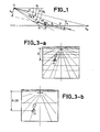
- the invention uses the perspective image of the exterior landscape in front of the aircraft, obtained either in direct vision, or by means of a sensor or otherwise (synthetic relief, for example).
- Height holding can be achieved according to the invention either by the pilot, by the use of an adequate figure superimposed on this image, or by automatic piloting with a suitable control device.
- the subject of the present invention is a method of assisting in the holding of height in air navigation, essentially characterized in that it consists, for any point of the image of the landscape overflown by the plane, identified by its angle of site (e -p) relative to the speed vector of the aircraft, and located in an area between a lower site limit and an upper site limit, on the path of the aircraft, to detect a possible difference between the angular speed of travel of this point relative to the airplane, function of the height - (h, H) of later crossing of this point by the airplane, under identical piloting conditions, and an angular speed of travel of reference, corresponding to a set height (h o , H o ), for the plane to cross a point at the same site (8 -p), under identical piloting conditions, and to modify the piloting of the airplane, in the event of a difference between these angular speeds of travel, so as to reduce these differences.
- the invention is based on these relationships.
- the angle i designates the angle of incidence of the aircraft, that is to say the angle between the longitudinal axis of the aircraft, or horizontal fuselage reference (for short RHF) of the airplane and the direction of the speed vector.
- the scrolling speed ⁇ is obtained for each of the points of the image, by the ratio where ⁇ represents the offset in site of each point of the landscape between the instants t and t + Ot.
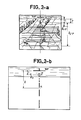
- ⁇ ⁇ is highlighted in FIGS. 3a and 3b respectively representing the position of the same element of the landscape on the images obtained at two successive instants t and t + At.
- ⁇ h is. can be used directly as an autopilot input for "vertical" piloting of the aircraft (associated with the usual information from the aircraft central unit).
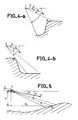
- FIG. 4a an airplane A has been shown approaching a hill.
- the summit B of the hill will be taken into account relatively early in the determination of the future trajectory of the aircraft, which leads to pass over the valley with a height greater than the setpoint h o . It is therefore advantageous to choose in such a case a higher value ⁇ 1 .
- the upper limit (e -p) is chosen so as to make it possible to carry out the resource necessary to overcome an obstacle with the guard height h o , and with a load factor of vertical evolution N normal in flight at low altitude (for example ⁇ 0.5) and crossing the obstacle on a re-canceled slope, which gives: where r is the reaction time to vary the load factor, hence:
- This limit (6 -p) 2 can also be fixed by the field which is available on site in the visualization through which or in which the terrain to be overflown is observed.
- the advantage of this variant lies in the fact that the imposed trajectory is practically independent of the deviation, at a given time, from the desired trajectory.
- the trajectories of the planes A, and A2 quickly join in controlling the center of gravity, while in controlling the vector speed, they remain distinct.
- vertex B is crossed horizontally, while in speed vector control it is crossed with a slope, therefore with overtaking.
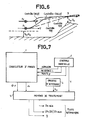
- FIG. 7 shows a device which can be used in the case of automatic terrain monitoring.
- This device includes an image correlator 1 for measuring the angular speed of travel at each of the points of the considered area of the image.
- This zone is defined by the values ⁇ 1 , ⁇ 2 and by the values ⁇ ⁇ g in bearing around the trajectory of the aircraft (represented by dotted lines in FIG. 8) which is predicted according to the angle of the the airplane and the load factor.
- the correlation is carried out by small limited elements of this area, as shown in Figure 8, and allows to obtain the offset in site ⁇ ( ⁇ -p), or offset according to the vertical of the image, from any point of the zone explored between two successive instants t and t + At, from which the angular speed of travel is deduced for all points in the explored area.
- This correlator receives from the inertial unit 2 of the airplane the information necessary for locating the various points of this image, namely the position of the horizon, the value of the angle of incidence i of the airplane, the value of the slope p, and the value of the plane's angle of inclination (giving the vertical of the image).
- the processing means 3 comprise for this elementary circuits performing the elementary functions X,:, -, sin, etc., and arranged so as to perform the desired function.
- the processing means 3 also make it possible to detect, according to known processing methods, the value at h min among the set of values A h obtained for the different points of the area explored.
- the point corresponding to A h mln can be reinforced on the display.
- the values ⁇ h min and g are supplied to the autopilot.
- Derivative ( ⁇ h) is also provided to allow loop stabilization; it is for example obtained by the calculation of:
- the device thus described corresponds to the case where the crossing height h of the different points on the ground is measured by reference to the direction of the speed vector.
Landscapes
- Engineering & Computer Science (AREA)
- Physics & Mathematics (AREA)
- General Physics & Mathematics (AREA)
- Radar, Positioning & Navigation (AREA)
- Remote Sensing (AREA)
- Aviation & Aerospace Engineering (AREA)
- Automation & Control Theory (AREA)
- Traffic Control Systems (AREA)
- Navigation (AREA)
Applications Claiming Priority (2)
| Application Number | Priority Date | Filing Date | Title |
|---|---|---|---|
| FR8511500A FR2585483B1 (fr) | 1985-07-26 | 1985-07-26 | Procede et dispositif d'aide a la tenue de hauteur dans la navigation aerienne |
| FR8511500 | 1985-07-26 |
Publications (1)
| Publication Number | Publication Date |
|---|---|
| EP0210902A1 true EP0210902A1 (de) | 1987-02-04 |
Family
ID=9321698
Family Applications (1)
| Application Number | Title | Priority Date | Filing Date |
|---|---|---|---|
| EP86401490A Withdrawn EP0210902A1 (de) | 1985-07-26 | 1986-07-04 | Verfahren und Vorrichtung zur Hilfe für die Einhaltung der Höhe in der Luftnavigation |
Country Status (3)
| Country | Link |
|---|---|
| US (1) | US4773017A (de) |
| EP (1) | EP0210902A1 (de) |
| FR (1) | FR2585483B1 (de) |
Families Citing this family (5)
| Publication number | Priority date | Publication date | Assignee | Title |
|---|---|---|---|---|
| GB2394702A (en) * | 2002-10-30 | 2004-05-05 | Trw Ltd | Video enhanced stability control in road vehicles |
| CN105955307B (zh) * | 2016-02-18 | 2020-07-10 | 青岛克路德机器人有限公司 | 一种消防水炮喷水落点的定位方法及消防机器人 |
| CN106292699B (zh) * | 2016-08-03 | 2017-12-12 | 广州极飞科技有限公司 | 无人机仿地飞行的方法、装置和无人机 |
| WO2018081952A1 (en) | 2016-11-02 | 2018-05-11 | SZ DJI Technology Co., Ltd. | Systems and methods for height control of a movable object |
| CN106705969B (zh) * | 2017-02-22 | 2020-04-28 | 西安应用光学研究所 | 无人机光电系统手动模式瞄准线轨迹拟合方法 |
Citations (2)
| Publication number | Priority date | Publication date | Assignee | Title |
|---|---|---|---|---|
| FR1168037A (fr) * | 1956-12-04 | 1958-12-03 | Jean Turck Ets | Altimètre-variomètre optique pour faibles altitudes |
| US3076095A (en) * | 1956-09-05 | 1963-01-29 | Texas Instruments Inc | Method and apparatus for determining altitude |
Family Cites Families (3)
| Publication number | Priority date | Publication date | Assignee | Title |
|---|---|---|---|---|
| DE2641447C2 (de) * | 1976-09-15 | 1983-11-24 | Vereinigte Flugtechnische Werke Gmbh, 2800 Bremen | Anordnung zur navigatorischen Steuerung von Flugkörpern |
| US4527161A (en) * | 1981-09-08 | 1985-07-02 | The United States Of America As Represented By The Secretary Of The Navy | 3D Imaging with stepped frequency waveforms and monopulse processing |
| US4490719A (en) * | 1981-11-27 | 1984-12-25 | United Technologies Corporation | Polarization controlled map matcher missile guidance system |
-
1985
- 1985-07-26 FR FR8511500A patent/FR2585483B1/fr not_active Expired
-
1986
- 1986-07-04 EP EP86401490A patent/EP0210902A1/de not_active Withdrawn
- 1986-07-23 US US06/888,378 patent/US4773017A/en not_active Expired - Fee Related
Patent Citations (2)
| Publication number | Priority date | Publication date | Assignee | Title |
|---|---|---|---|---|
| US3076095A (en) * | 1956-09-05 | 1963-01-29 | Texas Instruments Inc | Method and apparatus for determining altitude |
| FR1168037A (fr) * | 1956-12-04 | 1958-12-03 | Jean Turck Ets | Altimètre-variomètre optique pour faibles altitudes |
Also Published As
| Publication number | Publication date |
|---|---|
| FR2585483B1 (fr) | 1987-10-09 |
| US4773017A (en) | 1988-09-20 |
| FR2585483A1 (fr) | 1987-01-30 |
Similar Documents
| Publication | Publication Date | Title |
|---|---|---|
| EP1891618B1 (de) | Verfahren und system zur hilfe bei der flugkontrolle eines tieffliegenden flugzeugs | |
| EP2497555B1 (de) | Verfahren zum Steuern einer einem Kurvenflug folgenden Drohne mit Drehflügeln und mehreren Rotoren | |
| CA2508287C (fr) | Procede de validation d'une contrainte de plan de vol | |
| EP2431084A1 (de) | Verfahren zum Steuern einer Drohne mit schwenkbarer Tragfläche und mehreren Rotoren | |
| FR2844607A1 (fr) | Systeme d'assistance au pilotage de l'altitude et de la vitesse horizontale, perpendiculaire a l'aplomb, d'un aeronefs equipes de ce systeme | |
| EP1984798B1 (de) | Verfahren und system zur steuerung eines flugzeuges | |
| EP0775953B1 (de) | Steuermethode im Tiefflug | |
| EP3276591A1 (de) | Drohne mit einem hindernisausweichsystem | |
| FR2988868A1 (fr) | Procede de pilotage d'un drone a voilure tournante a rotors multiples avec estimation et compensation du vent lateral | |
| FR3022340A1 (fr) | Procede et dispositif de determination d'une consigne de controle d'un aeronef, produit programme d'ordinateur et aeronef associes | |
| CA2502622C (fr) | Procede et dispositif de guidage automatique d'un aeronef, pour un vol au moins en partie a basse altitude | |
| FR3018364A1 (fr) | Procede de determination d'une loi de guidage d'evitement d'obstacle par un aeronef, produit programme d'ordinateur, systeme electronique et aeronef associes | |
| WO2015055769A1 (fr) | Dispositif et procédé de repérage de terrain en vol pour microdrone | |
| CA2640521C (fr) | Systeme de commande electrique pour une gouverne de direction d'un avion | |
| FR2495313A1 (fr) | Circuit de calcul d'inclinaison longitudinale pour un aeronef | |
| EP2957975A1 (de) | Steuerverfahren und -vorrichtung mindestens eines kontrollsystems eines stellglieds eines luftfahrzeugs, entsprechendes computerprogramm-produkt und entsprechendes luftfahrzeug | |
| EP0210902A1 (de) | Verfahren und Vorrichtung zur Hilfe für die Einhaltung der Höhe in der Luftnavigation | |
| FR2733061A1 (fr) | Dispositif optoelectronique d'aide au pilotage d'un aeronef par mauvaise visibilite | |
| FR2513373A1 (fr) | Perfectionnements apportes aux installations gyroscopiques de navigation assurant des fonctions de pilotage ou de stabilisation | |
| CA2407166C (fr) | Procede et dispositif pour afficher un vecteur vitesse d'un aeronef | |
| FR2925710A1 (fr) | Procede et dispositif de modification d'une trajectoire de vol pour realiser une manoeuvre d'espacement. | |
| EP0985900A1 (de) | Verfahren und Vorrichtung zum Lenken eines Flugkörpers, insbesondere einer Kampfrakete, auf ein Ziel | |
| EP0285463B1 (de) | Vorrichtung zur Führung eines aerodynamischen Luftfahrzeuges mit Hilfe eines Merkmales der äusseren Umgebung, das der Pilot bestimmt | |
| EP0631111B1 (de) | Verfahren und Vorrichtung zum Bestimmen der Position eines Flugkörpers | |
| FR3033907A1 (fr) | Procede et dispositif d'aide au pilotage d'un aeronef lors d'un vol parabolique. |
Legal Events
| Date | Code | Title | Description |
|---|---|---|---|
| PUAI | Public reference made under article 153(3) epc to a published international application that has entered the european phase |
Free format text: ORIGINAL CODE: 0009012 |
|
| AK | Designated contracting states |
Kind code of ref document: A1 Designated state(s): DE GB |
|
| 17P | Request for examination filed |
Effective date: 19870701 |
|
| RAP3 | Party data changed (applicant data changed or rights of an application transferred) |
Owner name: THOMSON-CSF |
|
| STAA | Information on the status of an ep patent application or granted ep patent |
Free format text: STATUS: THE APPLICATION HAS BEEN WITHDRAWN |
|
| 18W | Application withdrawn |
Withdrawal date: 19890708 |
|
| RIN1 | Information on inventor provided before grant (corrected) |
Inventor name: ROBIN, LEON Inventor name: PRESSIAT, ROBERT Inventor name: MURGUE, JEAN-PIERRE |