EP0210766A2 - Adaptive control system for an internal combustion engine - Google Patents
Adaptive control system for an internal combustion engine Download PDFInfo
- Publication number
- EP0210766A2 EP0210766A2 EP86305221A EP86305221A EP0210766A2 EP 0210766 A2 EP0210766 A2 EP 0210766A2 EP 86305221 A EP86305221 A EP 86305221A EP 86305221 A EP86305221 A EP 86305221A EP 0210766 A2 EP0210766 A2 EP 0210766A2
- Authority
- EP
- European Patent Office
- Prior art keywords
- engine
- slope
- input
- control device
- ignition timing
- Prior art date
- Legal status (The legal status is an assumption and is not a legal conclusion. Google has not performed a legal analysis and makes no representation as to the accuracy of the status listed.)
- Granted
Links
Images


Classifications
-
- F—MECHANICAL ENGINEERING; LIGHTING; HEATING; WEAPONS; BLASTING
- F02—COMBUSTION ENGINES; HOT-GAS OR COMBUSTION-PRODUCT ENGINE PLANTS
- F02P—IGNITION, OTHER THAN COMPRESSION IGNITION, FOR INTERNAL-COMBUSTION ENGINES; TESTING OF IGNITION TIMING IN COMPRESSION-IGNITION ENGINES
- F02P5/00—Advancing or retarding ignition; Control therefor
- F02P5/04—Advancing or retarding ignition; Control therefor automatically, as a function of the working conditions of the engine or vehicle or of the atmospheric conditions
- F02P5/145—Advancing or retarding ignition; Control therefor automatically, as a function of the working conditions of the engine or vehicle or of the atmospheric conditions using electrical means
- F02P5/15—Digital data processing
- F02P5/1502—Digital data processing using one central computing unit
- F02P5/1512—Digital data processing using one central computing unit with particular means concerning an individual cylinder
-
- F—MECHANICAL ENGINEERING; LIGHTING; HEATING; WEAPONS; BLASTING
- F02—COMBUSTION ENGINES; HOT-GAS OR COMBUSTION-PRODUCT ENGINE PLANTS
- F02D—CONTROLLING COMBUSTION ENGINES
- F02D41/00—Electrical control of supply of combustible mixture or its constituents
- F02D41/02—Circuit arrangements for generating control signals
- F02D41/14—Introducing closed-loop corrections
- F02D41/1401—Introducing closed-loop corrections characterised by the control or regulation method
- F02D41/1408—Dithering techniques
-
- F—MECHANICAL ENGINEERING; LIGHTING; HEATING; WEAPONS; BLASTING
- F02—COMBUSTION ENGINES; HOT-GAS OR COMBUSTION-PRODUCT ENGINE PLANTS
- F02D—CONTROLLING COMBUSTION ENGINES
- F02D41/00—Electrical control of supply of combustible mixture or its constituents
- F02D41/24—Electrical control of supply of combustible mixture or its constituents characterised by the use of digital means
- F02D41/2406—Electrical control of supply of combustible mixture or its constituents characterised by the use of digital means using essentially read only memories
- F02D41/2425—Particular ways of programming the data
- F02D41/2429—Methods of calibrating or learning
- F02D41/2432—Methods of calibration
-
- F—MECHANICAL ENGINEERING; LIGHTING; HEATING; WEAPONS; BLASTING
- F02—COMBUSTION ENGINES; HOT-GAS OR COMBUSTION-PRODUCT ENGINE PLANTS
- F02D—CONTROLLING COMBUSTION ENGINES
- F02D41/00—Electrical control of supply of combustible mixture or its constituents
- F02D41/24—Electrical control of supply of combustible mixture or its constituents characterised by the use of digital means
- F02D41/2406—Electrical control of supply of combustible mixture or its constituents characterised by the use of digital means using essentially read only memories
- F02D41/2425—Particular ways of programming the data
- F02D41/2429—Methods of calibrating or learning
- F02D41/2451—Methods of calibrating or learning characterised by what is learned or calibrated
-
- F—MECHANICAL ENGINEERING; LIGHTING; HEATING; WEAPONS; BLASTING
- F02—COMBUSTION ENGINES; HOT-GAS OR COMBUSTION-PRODUCT ENGINE PLANTS
- F02P—IGNITION, OTHER THAN COMPRESSION IGNITION, FOR INTERNAL-COMBUSTION ENGINES; TESTING OF IGNITION TIMING IN COMPRESSION-IGNITION ENGINES
- F02P5/00—Advancing or retarding ignition; Control therefor
- F02P5/04—Advancing or retarding ignition; Control therefor automatically, as a function of the working conditions of the engine or vehicle or of the atmospheric conditions
- F02P5/045—Advancing or retarding ignition; Control therefor automatically, as a function of the working conditions of the engine or vehicle or of the atmospheric conditions combined with electronic control of other engine functions, e.g. fuel injection
-
- F—MECHANICAL ENGINEERING; LIGHTING; HEATING; WEAPONS; BLASTING
- F02—COMBUSTION ENGINES; HOT-GAS OR COMBUSTION-PRODUCT ENGINE PLANTS
- F02P—IGNITION, OTHER THAN COMPRESSION IGNITION, FOR INTERNAL-COMBUSTION ENGINES; TESTING OF IGNITION TIMING IN COMPRESSION-IGNITION ENGINES
- F02P5/00—Advancing or retarding ignition; Control therefor
- F02P5/04—Advancing or retarding ignition; Control therefor automatically, as a function of the working conditions of the engine or vehicle or of the atmospheric conditions
- F02P5/145—Advancing or retarding ignition; Control therefor automatically, as a function of the working conditions of the engine or vehicle or of the atmospheric conditions using electrical means
- F02P5/1455—Advancing or retarding ignition; Control therefor automatically, as a function of the working conditions of the engine or vehicle or of the atmospheric conditions using electrical means by using a second control of the closed loop type
-
- F—MECHANICAL ENGINEERING; LIGHTING; HEATING; WEAPONS; BLASTING
- F02—COMBUSTION ENGINES; HOT-GAS OR COMBUSTION-PRODUCT ENGINE PLANTS
- F02B—INTERNAL-COMBUSTION PISTON ENGINES; COMBUSTION ENGINES IN GENERAL
- F02B1/00—Engines characterised by fuel-air mixture compression
- F02B1/02—Engines characterised by fuel-air mixture compression with positive ignition
- F02B1/04—Engines characterised by fuel-air mixture compression with positive ignition with fuel-air mixture admission into cylinder
-
- Y—GENERAL TAGGING OF NEW TECHNOLOGICAL DEVELOPMENTS; GENERAL TAGGING OF CROSS-SECTIONAL TECHNOLOGIES SPANNING OVER SEVERAL SECTIONS OF THE IPC; TECHNICAL SUBJECTS COVERED BY FORMER USPC CROSS-REFERENCE ART COLLECTIONS [XRACs] AND DIGESTS
- Y02—TECHNOLOGIES OR APPLICATIONS FOR MITIGATION OR ADAPTATION AGAINST CLIMATE CHANGE
- Y02T—CLIMATE CHANGE MITIGATION TECHNOLOGIES RELATED TO TRANSPORTATION
- Y02T10/00—Road transport of goods or passengers
- Y02T10/10—Internal combustion engine [ICE] based vehicles
- Y02T10/40—Engine management systems
Definitions
- This invention relates to an adaptive control system for an internal combustion engine and further relates to a method of operating an internal combustion engine.
- oxides of nitrogen are associated with high temperatures within the combustion chamber. The highest temperatures occur with mixtures whose composition is close to stoichiometric. Under these conditions, there is little free oxygen to participate in a formation of oxides of nitrogen. Therefore, the rate of formation of oxides of nitrogen is greatest with mixtures containing some excess air. Formation of oxides of nitrogen is reduced if peak temperature during combustion is reduced by diluting the mixture either with excess air or with exhaust gas or by water injection. The temperature may also be reduced by reducing the compression ratio or retarding ignition timing but these approaches lead to increased fuel consumption.
- Modern systems for controlling ignition timing and fuel composition in an internal combustion engine make use of digital "maps". These maps comprise memories pre-programmed with data relating to ignition timing and fuel composition for a multiplicity of combinations of values of two different engine operating parameters such as engine speed and manifold pressure. These maps represent very complex surfaces which are unobtainable using mechanical cams or simple electronic function generators and so they provide a great improvement over the earlier arrangements. However, they do not provide a completely adequate answer to emission and efficiency problems since there are many variables which cannot be taken into account such as fuel composition and volatility, the effects of deposits on the engine cylinder head which in turn affect the flame speed, and changes in the accuracy of the operation of the equipment which controls the fuel mixture, and variations in ignition energy and spark gap.
- One such closed loop system uses an exhaust gas oxygen sensor. This system can compensate for variations in fuel composition and for variations in the air:fuel ratio in the mixture, but it cannot compensate for variations in compression ratio or for variations in the amount of exhaust gas recirculated where exhaust gas is used to dilute the mixture.
- Another system uses a cylinder pressure sensor which can detect the position of the crankshaft at which peak pressure occurs. As the position at which peak pressure occurs is related to flame speed, this system can be used to control the generation of oxides of nitrogen. Unfortunately, presently known cylinder pressure sensors cannot meet the requirements of low cost and reliability.
- Another system uses a flame front ionisation sensor to measure the time taken for the flame to traverse the cylinder head and thereby measure flame speed directly.
- the sensor has to be positioned carefully and this reduces the freedom to design the shape of the cylinder head for low emissions and good fuel consumption.
- a method of controlling an internal combustion engine having two control inputs both of which affect an engine output comprising periodically perturbing one of said inputs about a base value which is established in accordance with the engine operating conditions, monitoring said engine output, determining the slope of engine output with respect to said one input, and controlling the other input so as to obtain a desired value of said slope.
- the desired value of said slope is established continuously as a function of the operating conditions.
- said one input is a control input to an ignition timing control device and said other input is a control input to a mixture composition control device.
- ignition timing and mixture composition are related in the following way.
- mixture composition is defined by a particular value of ignition timing and a particular value of the slope of engine output with respect to ignition timing.
- accuracy in ignition timing is normally well maintained.
- the desired value of the slope is zero as this value results in maximum torque output.
- the ignition angle is usually retarded from the position for optimum torque output so as to reduce further the emissions of unburnt hydrocarbons.
- an adaptive control system for an internal combustion engine having two control inputs both of which affect an engine output comprising means for establishing a base value for one of said inputs as a function of engine operating conditions, means for periodically perturbing said one input about said base value, means for monitoring said engine output, means for determining the slope of engine output with respect to said one input, and means for controlling the other input so as to obtain a desired value of said slope.
- said one input is an input to an injection timing control and the other input is a mixture composition control of one of the types known in such engines, such as an exhaust gas recirculation control system.
- the graphs a, b, c, d indicate lines of constant torque plotted on axes representing air/fuel ratio and ignition timing angle. These graphs are obtained by running an engine on a test bench at a specific speed and air supply rate and measuring the torque obtained for different values of ignition angle and air/fuel ratio. Specifically, the engine is run with the air flow and ignition timing angle set to specific values. The fuelling setting of the engine and the braking load on the engine are adjusted until a specific fuel flow and engine speed are obtained. The torque is then noted.
- isotorque curve d Points on the air/fuel ratio against ignition timing angle graph at which one particular level of torque is obtained are joined to provide the isotorque curve d.
- isotorque curves c, b and a can be drawn for further successively higher levels of torque.
- there is a slope vector which points in the direction which produces the maximum increase in torque. Everywhere along an isotorque curve, the slope vector is at right-angles to the curve since travel along the isotorque curve produces no change in torque.
- the points at which the isotorque curves are parallel to the ignition timing axis are points at which there is no component of the slope vector in the ignition timing direction.
- line e represents a function relating ignition timing to air/fuel ratio.
- each value of air/fuel ratio is defined by a specific ignition timing value.
- a specific air/fuel ratio can be defined by a specific ignition timing value together with the associated value of the slope of engine torque with respect to ignition timing.
- an optimum combination of ignition timing and air/fuel ratio may be selected.
- the air/fuel ratio is selected so that the mixture is lean enough to prevent generation of excessive amounts of oxides of nitrogen but sufficiently rich to obtain efficient performance and avoid misfires.
- the ignition timing is a point on curve e as such points correspond to maximum torque output. However, under certain conditions a point away from-curve e will be chosen. For. example, during idling it may be desired to retard the ignition timing so as to reduce the emission of unburnt hydrocarbons.
- the slope of engine output with respect to engine speed is also noted.
- the ignition timing value is set to the optimum value for the engine operating conditions.
- the slope of engine output with respect to ignition timing is measured and the air/fuel ratio is then adjusted until the selected value of the slope is achieved.
- this value of tne slope is achieved, the flame speed will be at its optimum value and correspond to the air/fuel ratio which was selected to correspond to the particular value of the ignition timing value.
- engine torque has been used as a parameter to define engine output.
- Engine output can also be defined by engine speed or engine power and engine speed is used in the example given below.
- An engine 10 has an electronic fuel control device 11.
- the device 11 is an electronic fuel injection control device of known type in which a separate injector for each cylinder is arranged to inject fuel into the branch of the air intake manifold leading to that cylinder. Injection is initiated at a specific point in the operating cycle of the engine and the fuel control receives a fuel quantity input signal which determines the duration of injector opening in each cycle.
- the engine 10 has an ignition control device 12 which, in well known manner, causes the individual spark plugs of the engine to be fired at crankshaft angles determined by a spark angle input signal to the control 12.
- the engine 10 has a crankshaft position transducer 10a and another transducer 10b which measures air intake manifold pressure as a parameter representing load demand.
- the transducer 10b could measure another parameter representing load demand such as throttle angle.
- the crankshaft position transducer is a pick-up which coacts with a toothed wheel on the crankshaft.
- An arrangement is incorporated to enable a datum position of the crankshaft to be recognised. Such an arrangement may be constituted by a circuit or a computer program to recognise a missing tooth positioned on the toothed wheel.
- a suitable arrangement is disclosed in GB-A-2142436.
- crankshaft positon signals derived from the transducer 10a are supplied to both the fuel and ignition control devices 11, 12 to enable the fuel injection and ignition operations to be properly synchronised with engine operation.
- the crankshaft position signal is also supplied to a speed calculator 13 which provides a frequently updated signal representing the current speed of the crankshaft.
- the speed signal and the manifold pressure signal are supplied to three "map" type demand signal generators.
- One of these is an ignition advance angle demand map 14 which provides an output representing the selected ignition advance angle for the current value of engine speed and manifold pressure.
- Another of the maps is a fuel demand map 15 which contains approximate values of the fuel demand signal to be supplied to the fuel control device 11 to obtain the desired flame speed at each combination of engine speed and manifold pressure.
- the third map is a slope demand map 16.
- the map 16 contains the value of the slope of engine speed with respect to ignition timing angle which corresponds to the selected values of ignition advance angle and air/fuel ratio.
- the desired value of the slope is zero. But, as explained above, in some operating conditions such as idling, a positive slope is required for minimum emissions.
- Each of the above described maps is conveniently in the form of a digital memory in which the signals from the speed calculator 13 and the manifold pressure transducer 10b are combined together in accordance with some predetermined rule to form an address word and the demand is stored as a word of appropriate length at that memory address.
- the ignition timing angle signal (or word) from map 14 is supplied to the ignition control device 12 via a summer 17 which also receives a perturbation signal from a perturbation generator 18, which has an input from a clock.
- the perturbation signal is alternately positive and negative and hence the ignition timing angle signal supplied to the ignition control device 12 is varied cyclically to advance and retard the ignition angle by a small amount.
- the perturbation signal is also supplied together with the signals from the transducer 10a to a slope detector 19.
- This detector also has an input from the clock and operates to monitor the effect of the perturbation in ignition timing angle on engine speed. Thus, it produces a signal corresponding to the actually detected value of the slope of engine speed with respect to the timing angle.
- This signal is supplied to an error detector 20 which compares the actual value of the slope with the demanded value derived from map 16.
- the resulting error signal varies in both magnitude and sign in accordance with the relationship between the desired and actual values of the slope.
- the error signal is applied to a controller 21 which is also connected to the clock. Controller 21 has an integrator transfer function.
- the output of controller 21 is applied to a summer 22 which subtracts the output of controller 21 from the fuel demand signal derived from the map 15.
- the resulting corrected fuel demand signal is applied to the fuel control device 11. It will be appreciated that other transfer functions for controller 21 could be used. For example, a proportional plus integral transfer function may be used so as to increase the speed
- the ignition timing angle is perturbed about the selected value for the operating conditions.
- the error signals derived by comparing the actual and desired values of the slope are integrated by controller 21 and the integral of these error signals is subtracted from the mapped fuel demand signal, thereby adjusting the quantity of fuel injected.
- the functional block shown in Figure 1 may be implemented with a microcomputer system as shown in Figure 3.
- the maps . 14, 15 and 16 are readily implemented using ROM whilst the perturbation generator is timed by a software counter.
- the generator output is added to the ignition advance angle word from map 14.
- the slope detector calculates the slope by reference to successive measurements of engine speed stored in microcomputer RAM.
- the integrator 21 is implemented with an air/fuel ratio correction schedule, stored in RAM, which is continuously updated in accordance with the error between the demanded slope and the actual slope.
- the microcomputer system comprises a microcomputer 30 which forms part of an Intel integrated circuit type 8097 which is connected conventionally to a program memory 31 (ROM type 27c 64) which contains all the programs required for the microcomputer and the maps 14, 15 and 16. Temporary data storage is provided in RAM 32 (Hitachi type 6116).
- the transducer lOa is as described in GB-A-2142436 and employs a toothed wheel having teeth at 10° intervals with a tooth missing at each of two reference locations 180° apart.
- the winding of this transducer is interfaced with the interrupt input I of the microcomputer 30 via an interface circuit 33 which operates mainly to filter out noise and provide clean squared pulses to the microcomputer input as each tooth passes the pick-up winding.
- these pulses are used to provide crankshaft position pulses at 10° intervals and reference pulses at two specific positions in each crankshaft revolution.
- the microcomputer 30 uses these pulses to calculate the engine speed and thereby performs the function of speed calculator 13.
- the transducer 10b is interfaced by an analog to digital converter 34 with the microcomputer 30.
- the converter 34 also forms part of the said Intel integrated circuit type 8097.
- a high speed output of computer 30 is connected to an ignition driver 35.
- the driver 35 includes an amplifier and provides the current to drive the ignition coil on and off.
- Another high speed output is connected to an injector driver 36 which supplies control signals for the individual fuel injectors. Since the teeth on the toothed wheel are positioned at 10° intervals, finer resolution is obtained by interpolation. For each interval, the interpolation is achieved by using the time taken for the passage of the previous 10° interval.
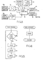
- FIG 4 there is shown a general arrangement of the modules which form the program and also the flow of data between these modules.
- the program comprises the modules MISDET, IGNLU, SAFIRE, and DWELL.
- the module IGNLU calls sub-modules LOOK UPl and LOOK UP2, and the module SAFIRE calls sub-modules MAP STORE and LOOK UP CORRECTION.
- Figure 4 also shows a fixed spark advance schedule 110 which contains the fixed spark advance values and which corresponds to map 14 shown in Figure 1.
- Figure 4 also shows a fixed air/fuel ratio schedule 112 which corresponds to the fixed air/fuel ratio map 16 shown in Figure 1.
- Figure 4 shows an air/fuel ratio correction schedule 111 which contains the correction values for the air/fuel ratio.
- the correction schedule is updated under the control of the sub-module MAP STORE in accordance with the error between the demanded slope and the actual slope.
- the values stored in the correction schedule 111 are used to correct the air/fuel ratio under the control of the sub-module LOOK UP CORRECTION.
- the sub-modules MAP STORE and LOOK UP CORRECTION together with the correction schedule 111 perform the function of the controller 21 of Figure 1.
- the module MISDET receives an interrupt signal TOOTH INTERRUPT and this module is executed each time a tooth is detected.
- a variable TOOTH is supplied to the module DWELL and represents the position of the crankshaft to within one tooth of the toothed wheel.
- This module MISDET compares the period between each tooth and thereby detects the missing tooth. When the missing tooth is detected, this module re-establishes a relationship between the variable TOOTH and the absolute position of the crankshaft.
- the module MISDE T also calculates the fire period and supplies this as a variable FIRE PERIOD to the modules IGNLU and SAFIRE.
- ignition occurs each time the crankshaft rotates through approximately 180°.
- Fire period is defined as the time which is taken for the crankshaft to rotate through exactly 180°.
- the module IGNLU receives a variable MAN PRESS representing manifold pressure and this variable is derived from the output signal of transducer 10b.
- each of the schedules 110, 111 and 112 the values are stored for each combination of engine speed and manifold pressure.
- the module IGNLU In order to address the schedules 110, 111 and 112, the module IGNLU generates address variables SPEED and LOAD corresponding respectively to engine speed and manifold pressure.
- the module IGNLU also calculates engine speed from the variable FIRE PERIOD and supplies this as a variable E N G SPEED to each of the modules SAFIRE and DWELL.
- the module IGNLU calls the sub-module LOOK UP2 which calculates the basic spark advance angle as a variable SPK ANG BASE by a standard interpolation process. This variable is then supplied to the module SAFIRE.
- the module IGNLU also calls the sub-module LOOK UP 1 which calculates the basic value for the air/fuel ratio by a similar standard interpolation process and supplies this value as a variable AFR BASE. This variable is also supplied to the module SAFIRE.
- the module IGNLU is executed after each ignition spark and the module SAFIRE is executed after module IG N LU.
- the module SAF I RE generates a perturbation value which varies alternately between +3° and -3° of spark advance angle at a frequency of 10Hz.
- the perturbation value is summed with the basic spark advance value SPK A N G BASE to provide a spark command value SPK ANG which is supplied to the module DWELL.
- the module SA F IRE also calls the sub-routine LOOK UP CORRECTION to obtain a correction value for the air/fuel ratio. This correction value is summed with the basic air/fuel ratio value AFR BASE to produce a commanded air/fuel ratio value AFR and this is also supplied to the module DWELL.
- the module SAFIRE also calculates the slope of engine output with respect to spark advance.
- the maximum effect of the perturbing on engine speed is found to occur almost half a perturbatiuon cycle after each change in the sign of the perturbation when the perturbation frequency is 10Hz.
- the ignition is advanced by 3° from the base value.
- the fire period associated with that advanced timing is recorded just before the ignition is retarded by 3° from the base value 50ms later.
- the fire period associated with that retarded timing is recorded just before the ignition is re-advanced by 3° from the base value 100ms after the start of the cycle.
- the second value for the fire period will be longer than the first value for the fire period.
- the first value for the fire period is subtracted from the second value and the resulting difference represents the slope.
- the module SAFI R E also calls the sub-module M AP STORE to update the air/fuel ratio correction schedule 111. Each time the schedule 111 is updated, this is performed in accordance with the following formula:
- k is a constant and SLOPE represents the actual value of the slope for engine speed with respect to spark advance.
- SLOPE represents the actual value of the slope for engine speed with respect to spark advance.
- the module DWELL uses the variables TOOTH and ENG SPEED to cause the microcomputer 30 to provide appropriate signals to the ignition driver 35 and injector driver 36 to achieve ignition and fuel injection at appropriate crankshaft positions with the air/fuel ratio set to the commanded value.
- Figures 5 and 6 show the sequence of operations of the modules set out in Figure 4.
- the program comprises a main program MAIN PROGRAM shown in Figure 5 and an interrupt routine TOOTH INTERRUPT shown in Figure 6.
- the interrupt routine shown in Figure 6 is performed each time an interrupt signal is produced following the detection of a tooth.
- the module MISDET is called.
- the variable TOOTH is compared with a constant START TOOTH in a step Sl.
- the constant START TOOTH is chosen to correspond to the correct angular position of the crankshaft to allow modules IGNLU, SAFIRE and DWELL to be executed before the occurrence of the next spark.
- these three modules are performed successively in steps S2, S3 and S4 before returning to step Sl.
- the modules IGNLU, SAFIRE and DWELL are executed synchronously with the firing of the engine and these modules are always executed between actual sparks.
- the ignition timing will be adjusted until the engine operates at point Z on line e.
- the engine will operate with an air/fuel ratio substantially richer than desired.
- the torque is maximized, the error in the fuelling may seriously worsen the generation of oxides of nitrogen.
- the ignition timing is set to a value which gives the maximum torque and the air/fuel ratio is adjusted until the desired ratio is achieved thereby achieving the required level of emissions for oxides of nitrogen.
- the present invention may also be applied to an engine in which the air/fuel ratio is controlled with an electronically trimmed carburettor or single point injector.
- an electronically trimmed carburettor or single point injector With such a carburettor, the engine will respond more slowly to changes in fuelling due to transport effects in the inlet manifold. In order to allow for this delay, a relatively low value is used for the constant k to give a slower rate of correction.
- the map 15 is replaced by an EGR demand map and fuel control device 11 is replaced by an- EGR control device.
- the EGR demand map contains approximate values for desired EGR ratios at the various combinations of engine speed and throttle angle.
- exhaust gas is added to the mixture of air and fuel at a position downstream from the carburettor.
- the amount of exhaust gas supplied is controlled by a solenoid operated valve in the duct supplying the exhaust gas.
- the signal supplied to the exhaust gas control device may simply correspond in magnitude to the signal which is supplied to the solenoid operated valve.
- the signal may be a command signal for a particular operating position of the valve, a feedback loop being supplied to ensure that the commanded position is achieved.
- the signal may command a specific value of exhaust gas flow and in this case a feedback loop is also required to ensure that this value is achieved.
- the timing of opening of the valves which permit the mixture to be induced into the cylinders is controlled. By opening these valves earlier than normal, some of the exhaust gas is sucked into the inlet manifold thus providing the required exhaust gas recirculation.
- an independent fuel control device such as a carburettor
- the operation of this is not controlled by the control system which is the subject of the present application.
- the ignition control device 12 the engine 10 and the crankshaft position transducer 10a remain as described previously with reference to Figure 1.
- the transducer 10b preferably measures throttle angle and the reason for this will be explained below.
- the ignition advance angle demand map 14 provides an output representing the ignition angle which, for the prevailing values of engine speed and throttle angle, will give the maximum torque when there is a desired value of EGR ratio chosen to achieve the required level of emissions.
- the ignition angle may be one which provides a known slope of engine speed with respect to spark timing and which corresponds to a desired level of EGR ratio.
- the third map 16 is exactly as described with reference to the embodiment of Figure 1. Also, the error detector 17, the summer 20, the perturbation generator 18, the slope detector 19 and the controller 21 are all as described with reference to Figure 1.
- controller 21 is, however, added to the output of the value obtained from the E GR demand map so as to ensure that the mixture is diluted when the measured slope is less than the desired slope as this indicates a more rapid flame speed than is desired.
- the integrator in controller 21 is preferably equipped with limits. This ensures that no further integration will occur after the output of summer 22 has reached the limit value for the EGR ratio even when the error signal which drove the signal to the limit persists. This ensures that the output of the integrator can move away from the limit quickly if the error polarity reverses.
- the map 14, the EG R demand map and the map 16 are preferably addressed with throttle angle rather than manifold pressure or air mass flow rate so as to avoid problems caused by parasitic control loops. These can arise if the map output influences EGR and the EGR then affects the addressing parameter such as manifold pressure or air mass flow rate and hence the map output. Throttle angle will not be affected in this way because it is controlled directly by the driver. Consequently, throttle angle will only be affected if changes in the E G R ratio produce torque changes and the driver reacts to these torque changes and changes the throttle angle. Changes in the throttle angle produced in this way are too weak to give rise to a stability problem.
- the present invention may also be used to provide feedback control for an engine equipped with exhaust gas recirculation.
- the valve used in exhaust gas recirculation is liable to changes in its characteristics as deposits build up over the life of the engine, such feedback is especially useful.
- the example shown in Figure 11 includes all the elements shown in Figure 1 and like elements are denoted by the same reference numerals.
- the output of crankshaft position transducer 10a is also supplied to a roughness detector 519.
- the roughness detector 519 may be as described in the above mentioned paper by Latsch et al.
- the output signal from the roughenss detector 519 is subtracted from the output of the roughness map in an error detector 520 and the resulting error signal is supplied to a roughness controller 521.
- the controller 521 operates in a similar manner to controller 21.
- the output signal from controller 21 is subtracted from an approximate fuel demand signal from maps 15 in summer 22 and the resulting signal is supplied to fuel control device 11. If the output of slope detector 19 is greater than the output of map 16, this indicates that the burn duration is too low and controller 21 causes a reduction in the air/fuel ratio.
- controller 521 is subtracted from an approximate EGR demand signal in a summer 522 and the resulting signal is supplied to an EGR control device 511. If the output of the roughness detector 519 is greater than the output of map 516, this indicates that a higher proportion of exhaust gas is required in the mixture and the controller 521 causes an increase in the flow rate of the exhaust gas.
- the example of Figure 11 has the advantage that the crankshaft position transducer 10a is used to provide feedback control of both the air/fuel ratio and the E GR ratio.
- the error signal from summer 520 represents the error in engine roughness and is used to control the EGR ratio. If excessive roughness is experienced, the system will increase the EGR ratio. In turn, this is likely to reduce the flame speed and hence the emission of oxides of nitrogen. Consequently, the slope of engine output with respect to spark advance will be positive and this will cause in an increase in the air/fuel ratio via fuel control device 11. This will bring the flame speed and hence the emissions of oxides of nitrogen and fuel consumption closer to the original target values.
- Link 580 ensures that corrections to the quantity of diluent in response to slope errors are made by changing the EGR ratio as well as the air/fuel ratio.
- Link 581 ensures that corrections to the composition of diluent in response to roughness errors are made by changing the air/fuel ratio as well as the EGR ratio.
- Links 580 and 581 may have gain and frequency characteristics arranged to reduce unwanted interactions in the fuel control device 11. This may be achieved using the diagonal dominance design method outlined in "Progress in the design of multivassible control systems" by H.H.Rosenbrock, Measurement and Control, Volume 4, 1971, pages 9 to 11.
- signals arising from errors in engine roughness can be fed to both the EGR control device 511 and the fuel control device 12 in such proportions, and with such relative speed, to ensure only a very slight effect on slope.
- signals arising from errors in slope can be fed to both the fuel control device 11 and the EG R control device 511 in such proportions, and with such relative speed, to ensure only a very slight effect on roughnes.
- particular cylinders may have faster burning characteristics than others due, for example, to thermal effects from neighbouring cylinders. If the present invention is used to control the mixture composition of individual cylinders or groups of cylinders, the emissions of oxides of nitrogen of the faster and slower burning cylinders can be brought closer to the required value.
- Control of the mixture composition of individual cylinders or groups of cylinders can compensate for poor distribution of the air or fuel which is caused, for example, by production tolerances or ageing in the fuel control devices.
- Figure 7 shows a system which is similar in principle to that shown in Figure 1 but in which the fuelling is optimised for each individual cylinder of a four cylinder engine.
- the ignition control device 12 of Figure 1 is replaced by four individual control devices 12a, l2b, 12c and 12d, each of which controls a respective individual cylinder.
- the fuel control device 11 of Figure 1 is replaced by four separate fuel control devices lla, llb, llc and lld, each of which controls the fuel supply to an individual cylinder.
- the maps 14, 15 and 16 in Figure 7 are exactly the same as described for Figure 1.
- the system of Figure 4 includes a counter 37 which determines which of the four cylinders is to have its fuelling optimised. Each cylinder is optimised for a fixed duration which corresponds to a preset number of engine fires. Counter 37 selects a different cylinder for optimisation after this duration expires.
- the counter 37 controls which cylinder is to be optimised via two selectors 38 and 39.
- the selector 39 determines which of four summers 17a, 17b, 17c, 17d receives the perturbation signal at a given time. Only the cylinder which is to be optimised is perturbed.
- Selector 38 determines which of the four integral controllers 21a, 21b, 21c, 21d is updated. These four controllers correspond to controller 21 described for Figure 1.
- the counter 37 ensures that the cylinder whose fuelling is updated is the same as the cylinder whose ignition is perturbed.
- Figure 7 After selecting a cylinder for optimisation, the operation of Figure 7 is similar to that of Figure 1.
- the ignition timing angle signal from map 14 is supplied to the ignition control devices 12a to 12d via summers 17a to 17d.
- the perturbation signal from the perturbation generator 18 is directed via selector 39 to the summer corresponding to the cylinder whose fuelling is to be optimised.
- the perturbation signal together with a signal from transducer 10a and a clock is supplied to the slope detector 19. This operates to monitor the effect of the perturbation in ignition angle on engine speed.
- the detector 19 produces an output signal proportional to the slope of engine speed with respect to ignition angle for the cylinder being optimised.
- This signal is supplied to the error detector 20 which compares the actual value of the slope with the demanded value derived from map 16.
- the resulting error signal is then directed via selector 38 to the controller 21a to 21d of the cylinder being optimised.
- the outputs of the four integral controllers 21a to 21d are applied to four summers 22a to 22d which subtract the output of the controller from the fuel demand signal derived from map 15.
- the resulting corrected fuel demand signals are applied to the respective fuel control devices lla to lld.
- the magnitude of the signal produced by slope detector 19 for an individual cylinder will be smaller than the magnitude of the corresponding signal for the system described with reference to Figure 1.
- the noise component in this signal is comparable with a noise component for the system described with reference to Figure 1.
- the controllers 21a to 21d of Figure 7 have nominally the same gain as the controller 21 of Figure 2. This results in a longer time for optimising the fuelling than required for the system of Figure 1.
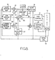
- FIG 8 there is shown a diagram of the functional components of an adaptive control system forming another embodiment of the present invention.
- parts which are substantially the same as those shown in Figure 1 have the same reference numerals.
- the map 14 of Figure 1 is replaced by a map 14A giving an output approximately representing desired ignition timing angle. This is not connected directly to the summer 17 but to a summer 22a which also receives the output of the controller 21.
- fuel demand map 15A instead of fuel demand map 15, there is an air/fuel ratio demand map 15A which contains values of the air/fuel ratio required at different combinations of speed and manifold pressure to achieve the required level of emissions of oxides of nitrogen.
- Controller 21 acts to reduce the slope error by generating a correction to the spark advance provided by map 14A. This correction is added to the approximate desired spark advance output from map 14A in summer 22A to provide a current estimate of the optimum spark advance which is then supplied via summer 17 to the ignition control 12.
- the current estimate of the optimum spark advance is also supplied from summer 22A to another map 23.
- Map 23 is used for obtaining an estimate of the actual existing air/fuel ratio.
- the digital memory has its address word defined by combining speed, manifold pressure and the current estimate of the optimum spark advance, the latter being the output of summer 22A.
- the words stored at the various addresses in this memory represent curves such as e from Figure 2.
- Map 15A and map 23 have their outputs compared by a summer 24, and the resulting air/fuel ratio error signal is integrated by a suitable controller 25 to provide the fuel demand signal to fuel control 11.
- the system shown in Figure 8 provides excellent control over emissions of oxides of nitrogen together with fuel efficient running of the engine.
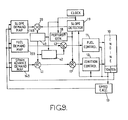
- FIG. 9 Another example of the invention is shown in Figure 9.
- the output of the error detector 20 is applied to a controller 40 (which may have an integral transfer characteristic for greater stability).
- the output of controller 40 is applied to a summer 41.
- the summer 41 adds the output of controller 40 to the output from the spark advance demand map 14B so as to correct ignition timing to the required value for the existing fuelling conditions.
- the ignition timing is controlled in the same way as in the prior art arrangement mentioned above.
- the output of the controller 40 is also applied to another controller 42, the output of which is added to the output of the fuel demand map 15Bby a summer 43.
- the controller 42 which may have an integral transfer characteristic, adjusts the air/fuel ratio so as to reduce the signal supplied to its input from controller 40.
- the spark advance is maintained at its optimum level substantially all the time since the ignition control loop can be given a relatively rapid response.
- the fuelling control loop under the influence of controller 42, however, operates relatively slowly but has the effect of slowly replacing correction of ignition timing by correction of the air/fuel ratio. In steady running conditions, the correction applied to the ignition timing will be reduced to zero.
- the system of Figure 9 adjusts the fuelling to the same value as is achieved in the system of Figure 1 but the response of the two systems to errors differs significantly.
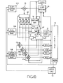
- Figure 10 shows the application of the principle of the system of Figure 6 to an engine in which ignition timing for each cylinder is controlled separately, but in which mixture composition is controlled jointly (for example by a carburettor or by exhaust recirculation).
- the functions of summers 41 and 17 have been combined, each ignition channel including a summer 45a, 45b, 45c, 45d.
- the perturbation signals are applied to these by a channel selector 47.
- the counter 46 also controls a selector 48 which routes the error signals from summer 20 to a set of controllers 40a, 40b, 40c, 40d, each of which is provided for a respective cylinder.
- An averaging circuit 49 receives the outputs of all controllers 40a to 40d and provides an output to controller 42 representing the average of the outputs of controllers 40a to 40d.
- the most positive (advancing) or most negative (retarding) correction signal from the controllers 40a to 40d may be selected for application to the controller 42.
- the invention has been described for use with a conventional mixture control device in which the mixture control device alters the rate of fuel flow whilst the rate of air flow or the rate of mixture flow is controlled by the driver of the vehicle in which the engine is installed.
- the invention is also applicable to unconventional systems in which the mixture control device alters the rate of air flow and the fuel flow is directly controlled by the driver.
- graphs equivalent to those shown in Figure 2 may be derived but with speed and fuel flow rate held constant rather than speed and air flow rate.
- Spark advance demand angles are then chosen for storage in spark advance demand map 14, and an air demand map would replace fuel demand map 15 in Figures 1 and 7.
- the data in maps 14 B and 15 B will be replaced as described above.
Abstract
Description
- This invention relates to an adaptive control system for an internal combustion engine and further relates to a method of operating an internal combustion engine.
- In view of the increasing stringency of emission control regulations in various countries in recent years, many attempts have been made to improve fuel supply systems of engines to reduce noxious exhaust emissions whilst maintaining good engine driveability.
- In one approach to reduce noxious emissions, fuel and air are supplied to the cylinders in stoichiometric proportions and the pollutants are removed by using a catalyst. This approach suffers from the disadvantages that the catalyst is liable to deteriorate with use and running an engine with a stoichiometric mixture results in a relatively high fuel consumption.
- In another approach, known as the "lean-burn" approach, a mixture containing excess air is supplied to the cylinders. Production of pollutants in the form of carbon monoxide and oxides of nitrogen is much less than with the stoichiometric approach. An arrangement using this approach is less prone to deterioration with time than an arrangement using the stoichiometric approach and this approach results in an improvement in fuel consumption in comparison with the stoichiometric approach.
- The formation of oxides of nitrogen is associated with high temperatures within the combustion chamber. The highest temperatures occur with mixtures whose composition is close to stoichiometric. Under these conditions, there is little free oxygen to participate in a formation of oxides of nitrogen. Therefore, the rate of formation of oxides of nitrogen is greatest with mixtures containing some excess air. Formation of oxides of nitrogen is reduced if peak temperature during combustion is reduced by diluting the mixture either with excess air or with exhaust gas or by water injection. The temperature may also be reduced by reducing the compression ratio or retarding ignition timing but these approaches lead to increased fuel consumption.
- In a combustion chamber, flame propagation after ignition occurs at a finite speed. It has been found that maximum efficiency occurs when the peak pressures are generated approximately 5° to 15° after a piston has passed the top dead centre position. In order to achieve this, ignition occurs before the piston reaches top dead centre.
- As the mixture is made progressively leaner, flame speed falls and ignition must be advanced progressively to maintain maximum efficiency. With very lean mixtures, or with high levels of exhaust gas recirculation, the flame speed becomes very low and ignition timing is very advanced. Consequently, the temperatures and pressures of the mixture at the moment of ignition are low and flame propagation is also low. Under these conditions, small variations in mixture composition and turbulence can lead to large variations in the time required to burn the mixture and these variations in cylinder pressure from cycle to cycle increase engine roughness.
- Consequently, it is necessary to control the mixture composition between a fast burning limit beyond which the generation of oxides of nitrogen exceeds a desirable level and a slow burning limit beyond which engine roughness becomes unacceptable or misfires occur. In practice, there is a narrow window of acceptable mixture composition between the two limits and this mixture composition is associated with an optimum ignition timing.
- Modern systems for controlling ignition timing and fuel composition in an internal combustion engine make use of digital "maps". These maps comprise memories pre-programmed with data relating to ignition timing and fuel composition for a multiplicity of combinations of values of two different engine operating parameters such as engine speed and manifold pressure. These maps represent very complex surfaces which are unobtainable using mechanical cams or simple electronic function generators and so they provide a great improvement over the earlier arrangements. However, they do not provide a completely adequate answer to emission and efficiency problems since there are many variables which cannot be taken into account such as fuel composition and volatility, the effects of deposits on the engine cylinder head which in turn affect the flame speed, and changes in the accuracy of the operation of the equipment which controls the fuel mixture, and variations in ignition energy and spark gap.
- Various closed loop systems have been proposed to overcome these variable factors.
- One such closed loop system uses an exhaust gas oxygen sensor. This system can compensate for variations in fuel composition and for variations in the air:fuel ratio in the mixture, but it cannot compensate for variations in compression ratio or for variations in the amount of exhaust gas recirculated where exhaust gas is used to dilute the mixture.
- Another system uses a cylinder pressure sensor which can detect the position of the crankshaft at which peak pressure occurs. As the position at which peak pressure occurs is related to flame speed, this system can be used to control the generation of oxides of nitrogen. Unfortunately, presently known cylinder pressure sensors cannot meet the requirements of low cost and reliability.
- Another system uses a flame front ionisation sensor to measure the time taken for the flame to traverse the cylinder head and thereby measure flame speed directly. The sensor has to be positioned carefully and this reduces the freedom to design the shape of the cylinder head for low emissions and good fuel consumption.
- In an article entitled "Electronic Spark Timing Control for Motor Vehicles" by Paul H. Schweitzer and Thomas W. Collins, published by The Society of Automotive Engineers as paper 780655,. and also in U.S. Patent 4026251, there is described a system for optimising ignition timing. In this system, small perturbations are superimposed on the ignition timing and the resulting changes in engine speed are used to determine the differential or slope of engine speed with respect to ignition timing. The ignition timing is then adjusted until the slope is zero.
- Although this system results in optimum ignition timing and, consequently, optimum engine output torque, for the prevailing fuel mixture, it does not compensate for errors in mixture composition. For example, it does not compensate for an error in mixture composition which results in excessive generation of oxides of nitrogen.
- Accordingly, it is an object of this invention to provide a new or improved method of operating an internal combustion engine and also a new or improved adaptive control system for an internal combustion engine in which the above-mentioned problems are overcome or reduced.
- According to one aspect of this invention there is provided a method of controlling an internal combustion engine having two control inputs both of which affect an engine output, said method comprising periodically perturbing one of said inputs about a base value which is established in accordance with the engine operating conditions, monitoring said engine output, determining the slope of engine output with respect to said one input, and controlling the other input so as to obtain a desired value of said slope.
- Preferably, the desired value of said slope is established continuously as a function of the operating conditions.
- Preferably, said one input is a control input to an ignition timing control device and said other input is a control input to a mixture composition control device.
- The applicants have found that ignition timing and mixture composition are related in the following way. For specified engine operating conditions, such as a specified value of engine speed and a specified value of manifold pressure, mixture composition is defined by a particular value of ignition timing and a particular value of the slope of engine output with respect to ignition timing. The applicants have also found that, whilst mixture composition is liable to the variations outlined above, accuracy in ignition timing is normally well maintained. Thus, if ignition timing is specified for each combination of operating conditions, and the mixture composition is adjusted so as to achieve a desired value of the slope of engine output with respect to ignition timing, the desired fuelling will be achieved. Thus, the present invention provides an extremely convenient way of compensating for errors in fuelling.
- Normally, the desired value of the slope is zero as this value results in maximum torque output. However, under certain operating conditions, it may be desirable to select a value other than zero. For example, under idling conditions, the ignition angle is usually retarded from the position for optimum torque output so as to reduce further the emissions of unburnt hydrocarbons.
- According to another aspect of this invention there is provided an adaptive control system for an internal combustion engine having two control inputs both of which affect an engine output, said system comprising means for establishing a base value for one of said inputs as a function of engine operating conditions, means for periodically perturbing said one input about said base value, means for monitoring said engine output, means for determining the slope of engine output with respect to said one input, and means for controlling the other input so as to obtain a desired value of said slope.
- Although the invention is particularly applicable to spark ignition petrol engines and the illustrative examples described hereinafter all relate to such engines, the invention is also applicable to compression ignition engines. In this case, in accordance with either of the aspects mentioned above, said one input is an input to an injection timing control and the other input is a mixture composition control of one of the types known in such engines, such as an exhaust gas recirculation control system.
- This invention will now be described in more detail, by way of example, with reference to the drawings in which:
- Figure 1 is a diagram of the functional components of an adaptive control system embodying this invention;
- Figure 2 is a graph in which the ignition angle required to give particular levels of torque is plotted against air/fuel ratio;
- Figure 3 is a block diagram of a microcomputer system which implements the functional components of Figure 1;
- Figure 4 is a layout diagram of the computer program for the control system of Figure 3;
- Figures 5 and 6 are flowcharts of the program; and
- Figures 7 to 11 are diagrams of the functional components of five further adaptive control systems embodying this invention.
- Referring firstly to Figure 2, the graphs a, b, c, d indicate lines of constant torque plotted on axes representing air/fuel ratio and ignition timing angle. These graphs are obtained by running an engine on a test bench at a specific speed and air supply rate and measuring the torque obtained for different values of ignition angle and air/fuel ratio. Specifically, the engine is run with the air flow and ignition timing angle set to specific values. The fuelling setting of the engine and the braking load on the engine are adjusted until a specific fuel flow and engine speed are obtained. The torque is then noted.
- Points on the air/fuel ratio against ignition timing angle graph at which one particular level of torque is obtained are joined to provide the isotorque curve d. Similarly, isotorque curves c, b and a can be drawn for further successively higher levels of torque. At any point in Figure 2, there is a slope vector which points in the direction which produces the maximum increase in torque. Everywhere along an isotorque curve, the slope vector is at right-angles to the curve since travel along the isotorque curve produces no change in torque. Hence the points at which the isotorque curves are parallel to the ignition timing axis are points at which there is no component of the slope vector in the ignition timing direction. The partial differential of torque with respect to ignition timing is therefore zero at these points which have been joined by line e on Figure 2. The same procedure is repeated for each combination of values of air flow rate and speed. It has been found by the applicants that the family of lines e thus derived is characteristic of the engine type being tested.
- Thus, for a specific engine speed and a specific air/fuel ratio, line e represents a function relating ignition timing to air/fuel ratio. Thus, using line e, each value of air/fuel ratio is defined by a specific ignition timing value.
- At each point not on line e, the partial differential or slope of engine torque with respect to ignition timing will have a non zero value. Using the points away from line e, a specific air/fuel ratio can be defined by a specific ignition timing value together with the associated value of the slope of engine torque with respect to ignition timing.
- At points anywhere in Figure 2 above and to the left of line e, the slope of engine torque with respect to ignition timing is negative. Below and to the right of line e, the slope is positive. The area below and to the right of curve e in Figure 2 represents fuel mixtures which do not have sufficient time to burn to make the maximum possible contribution to the work output of the engine. The area above and to the left of curve e in Figure 2 represents fuel mixtures which burn too quickly to make the maximum contribution.
- Whilst the engine is being tested to produce the curve shown in Figure 2, the emissions of pollutants, and especially nitrous oxides, are also measured.
- Using the results of these tests, for each engine speed and air flow rate, an optimum combination of ignition timing and air/fuel ratio may be selected. The air/fuel ratio is selected so that the mixture is lean enough to prevent generation of excessive amounts of oxides of nitrogen but sufficiently rich to obtain efficient performance and avoid misfires. Normally, the ignition timing is a point on curve e as such points correspond to maximum torque output. However, under certain conditions a point away from-curve e will be chosen. For. example, during idling it may be desired to retard the ignition timing so as to reduce the emission of unburnt hydrocarbons. For each selected combination of ignition timing and air/fuel ratio, the slope of engine output with respect to engine speed is also noted.
- The applicants have found that ignition timing can be established accurately and that the errors which occur when an engine is used are only minimal. In contrast, the factors which affect flame speed such as air/fuel ratio and compression ratio vary considerably and significant errors do occur when an engine is used. In the present invention, as will be explained in the various examples set out below, the ignition timing value is set to the optimum value for the engine operating conditions. The slope of engine output with respect to ignition timing is measured and the air/fuel ratio is then adjusted until the selected value of the slope is achieved. When this value of tne slope is achieved, the flame speed will be at its optimum value and correspond to the air/fuel ratio which was selected to correspond to the particular value of the ignition timing value.
- In the discussion of Figure 2 above, engine torque has been used as a parameter to define engine output. Engine output can also be defined by engine speed or engine power and engine speed is used in the example given below.
- Also, in the discussion of Figure 2, the air supply rate has been used as the parameter to define the load demand to which the engine is subjected. Fuel flow, mixture flow, throttle angle or inlet manifold pressure may also be used to. define load demand. In the examples given below, the manifold pressure is used. Referring now to Figure 1, there is shown the functional components of an adaptive control system embodying the principles set out above.
- An
engine 10 has an electronicfuel control device 11. Thedevice 11 is an electronic fuel injection control device of known type in which a separate injector for each cylinder is arranged to inject fuel into the branch of the air intake manifold leading to that cylinder. Injection is initiated at a specific point in the operating cycle of the engine and the fuel control receives a fuel quantity input signal which determines the duration of injector opening in each cycle. - The
engine 10 has anignition control device 12 which, in well known manner, causes the individual spark plugs of the engine to be fired at crankshaft angles determined by a spark angle input signal to thecontrol 12. - The
engine 10 has acrankshaft position transducer 10a and anothertransducer 10b which measures air intake manifold pressure as a parameter representing load demand. Alternatively, thetransducer 10b could measure another parameter representing load demand such as throttle angle. The crankshaft position transducer is a pick-up which coacts with a toothed wheel on the crankshaft. An arrangement is incorporated to enable a datum position of the crankshaft to be recognised. Such an arrangement may be constituted by a circuit or a computer program to recognise a missing tooth positioned on the toothed wheel. A suitable arrangement is disclosed in GB-A-2142436. The crankshaft positon signals derived from thetransducer 10a are supplied to both the fuel andignition control devices speed calculator 13 which provides a frequently updated signal representing the current speed of the crankshaft. - The speed signal and the manifold pressure signal are supplied to three "map" type demand signal generators. One of these is an ignition advance
angle demand map 14 which provides an output representing the selected ignition advance angle for the current value of engine speed and manifold pressure. - Another of the maps is a
fuel demand map 15 which contains approximate values of the fuel demand signal to be supplied to thefuel control device 11 to obtain the desired flame speed at each combination of engine speed and manifold pressure. - The values stored in the
maps - .The third map is a
slope demand map 16. For each combination of engine speed and manifold pressure, themap 16 contains the value of the slope of engine speed with respect to ignition timing angle which corresponds to the selected values of ignition advance angle and air/fuel ratio. For most combinations of values of speed and manifold pressure, the desired value of the slope is zero. But, as explained above, in some operating conditions such as idling, a positive slope is required for minimum emissions. - Each of the above described maps is conveniently in the form of a digital memory in which the signals from the
speed calculator 13 and themanifold pressure transducer 10b are combined together in accordance with some predetermined rule to form an address word and the demand is stored as a word of appropriate length at that memory address. - The ignition timing angle signal (or word) from
map 14 is supplied to theignition control device 12 via asummer 17 which also receives a perturbation signal from aperturbation generator 18, which has an input from a clock. - The perturbation signal is alternately positive and negative and hence the ignition timing angle signal supplied to the
ignition control device 12 is varied cyclically to advance and retard the ignition angle by a small amount. - The perturbation signal is also supplied together with the signals from the
transducer 10a to aslope detector 19. This detector also has an input from the clock and operates to monitor the effect of the perturbation in ignition timing angle on engine speed. Thus, it produces a signal corresponding to the actually detected value of the slope of engine speed with respect to the timing angle. This signal is supplied to anerror detector 20 which compares the actual value of the slope with the demanded value derived frommap 16. The resulting error signal varies in both magnitude and sign in accordance with the relationship between the desired and actual values of the slope. The error signal is applied to acontroller 21 which is also connected to the clock.Controller 21 has an integrator transfer function. The output ofcontroller 21 is applied to asummer 22 which subtracts the output ofcontroller 21 from the fuel demand signal derived from themap 15. The resulting corrected fuel demand signal is applied to thefuel control device 11. It will be appreciated that other transfer functions forcontroller 21 could be used. For example, a proportional plus integral transfer function may be used so as to increase the speed or stability of the control loop. - Thus, when the engine is running, the ignition timing angle is perturbed about the selected value for the operating conditions. The error signals derived by comparing the actual and desired values of the slope are integrated by
controller 21 and the integral of these error signals is subtracted from the mapped fuel demand signal, thereby adjusting the quantity of fuel injected. - For example, referring again to Figure 2, for the particular operating conditions shown there it may be desired to operate the engine at point Y. However, owing to errors in the
fuel control device 11, the value provided byfuel map 15 may cause the engine to operate at point X. As the air/fuel ratio is richer at point X than at the desired point Y, this could cause excessive emissions of oxides of nitrogen. However, the arrangement shown in Figure 1 will cause the air/fuel ratio to be adjusted until point Y is reached. Thus, despite errors infuel control device 11, the engine will operate with a combination of ignition advance angle and air/fuel ratio which results in low emissions and optimum engine output. - The functional block shown in Figure 1 may be implemented with a microcomputer system as shown in Figure 3. The maps . 14, 15 and 16 are readily implemented using ROM whilst the perturbation generator is timed by a software counter. The generator output is added to the ignition advance angle word from
map 14. The slope detector calculates the slope by reference to successive measurements of engine speed stored in microcomputer RAM. Theintegrator 21 is implemented with an air/fuel ratio correction schedule, stored in RAM, which is continuously updated in accordance with the error between the demanded slope and the actual slope. - As shown in Figure 3, the microcomputer system comprises a
microcomputer 30 which forms part of an Intel integrated circuit type 8097 which is connected conventionally to a program memory 31 (ROM type 27c 64) which contains all the programs required for the microcomputer and themaps - The transducer lOa is as described in GB-A-2142436 and employs a toothed wheel having teeth at 10° intervals with a tooth missing at each of two reference locations 180° apart. The winding of this transducer is interfaced with the interrupt input I of the
microcomputer 30 via an interface circuit 33 which operates mainly to filter out noise and provide clean squared pulses to the microcomputer input as each tooth passes the pick-up winding. As explained in GB-A-2142436, these pulses are used to provide crankshaft position pulses at 10° intervals and reference pulses at two specific positions in each crankshaft revolution. Themicrocomputer 30 uses these pulses to calculate the engine speed and thereby performs the function ofspeed calculator 13. Thetransducer 10b is interfaced by an analog todigital converter 34 with themicrocomputer 30. Theconverter 34 also forms part of the said Intel integrated circuit type 8097. - A high speed output of
computer 30 is connected to anignition driver 35. Thedriver 35 includes an amplifier and provides the current to drive the ignition coil on and off. Another high speed output is connected to aninjector driver 36 which supplies control signals for the individual fuel injectors. Since the teeth on the toothed wheel are positioned at 10° intervals, finer resolution is obtained by interpolation. For each interval, the interpolation is achieved by using the time taken for the passage of the previous 10° interval. - Referring to Figure 4, there is shown a general arrangement of the modules which form the program and also the flow of data between these modules. The program comprises the modules MISDET, IGNLU, SAFIRE, and DWELL. The module IGNLU calls sub-modules LOOK UPl and LOOK UP2, and the module SAFIRE calls sub-modules MAP STORE and LOOK UP CORRECTION. Figure 4 also shows a fixed
spark advance schedule 110 which contains the fixed spark advance values and which corresponds to map 14 shown in Figure 1. Figure 4 also shows a fixed air/fuel ratio schedule 112 which corresponds to the fixed air/fuel ratio map 16 shown in Figure 1. Furthermore, Figure 4 shows an air/fuelratio correction schedule 111 which contains the correction values for the air/fuel ratio. The correction schedule is updated under the control of the sub-module MAP STORE in accordance with the error between the demanded slope and the actual slope. The values stored in thecorrection schedule 111 are used to correct the air/fuel ratio under the control of the sub-module LOOK UP CORRECTION. Thus, the sub-modules MAP STORE and LOOK UP CORRECTION together with thecorrection schedule 111 perform the function of thecontroller 21 of Figure 1. - The module MISDET receives an interrupt signal TOOTH INTERRUPT and this module is executed each time a tooth is detected. A variable TOOTH is supplied to the module DWELL and represents the position of the crankshaft to within one tooth of the toothed wheel. This module MISDET compares the period between each tooth and thereby detects the missing tooth. When the missing tooth is detected, this module re-establishes a relationship between the variable TOOTH and the absolute position of the crankshaft. The module MISDET also calculates the fire period and supplies this as a variable FIRE PERIOD to the modules IGNLU and SAFIRE. In the present example, ignition occurs each time the crankshaft rotates through approximately 180°. Fire period is defined as the time which is taken for the crankshaft to rotate through exactly 180°.
- The module IGNLU receives a variable MAN PRESS representing manifold pressure and this variable is derived from the output signal of
transducer 10b. - In each of the
schedules schedules - The module IGNLU also calculates engine speed from the variable FIRE PERIOD and supplies this as a variable ENG SPEED to each of the modules SAFIRE and DWELL.
- The module IGNLU calls the sub-module LOOK UP2 which calculates the basic spark advance angle as a variable SPK ANG BASE by a standard interpolation process. This variable is then supplied to the module SAFIRE. The module IGNLU also calls the sub-module LOOK UP1 which calculates the basic value for the air/fuel ratio by a similar standard interpolation process and supplies this value as a variable AFR BASE. This variable is also supplied to the module SAFIRE.
- The module IGNLU is executed after each ignition spark and the module SAFIRE is executed after module IGNLU.
- The module SAFIRE generates a perturbation value which varies alternately between +3° and -3° of spark advance angle at a frequency of 10Hz. The perturbation value is summed with the basic spark advance value SPK ANG BASE to provide a spark command value SPK ANG which is supplied to the module DWELL.
- The module SAFIRE also calls the sub-routine LOOK UP CORRECTION to obtain a correction value for the air/fuel ratio. This correction value is summed with the basic air/fuel ratio value AFR BASE to produce a commanded air/fuel ratio value AFR and this is also supplied to the module DWELL.
- The module SAFIRE also calculates the slope of engine output with respect to spark advance. The maximum effect of the perturbing on engine speed is found to occur almost half a perturbatiuon cycle after each change in the sign of the perturbation when the perturbation frequency is 10Hz. Thus, in a perturbation cycle the ignition is advanced by 3° from the base value. The fire period associated with that advanced timing is recorded just before the ignition is retarded by 3° from the base value 50ms later. The fire period associated with that retarded timing is recorded just before the ignition is re-advanced by 3° from the base value 100ms after the start of the cycle. If the engine is operating under conditions such that advancing ignition causes acceleration and retarding ignition causes deceleration, the second value for the fire period will be longer than the first value for the fire period. The first value for the fire period is subtracted from the second value and the resulting difference represents the slope.
- The module SAFIRE also calls the sub-module MAP STORE to update the air/fuel
ratio correction schedule 111. Each time theschedule 111 is updated, this is performed in accordance with the following formula: - new correction = old correction + k x (SLOPE)
- In this formula, k is a constant and SLOPE represents the actual value of the slope for engine speed with respect to spark advance. As may be readily appreciated, the
schedule 111 is updated at the point corresponding to the prevailing operating conditions. - The module DWELL uses the variables TOOTH and ENG SPEED to cause the
microcomputer 30 to provide appropriate signals to theignition driver 35 andinjector driver 36 to achieve ignition and fuel injection at appropriate crankshaft positions with the air/fuel ratio set to the commanded value. - Figures 5 and 6 show the sequence of operations of the modules set out in Figure 4. The program comprises a main program MAIN PROGRAM shown in Figure 5 and an interrupt routine TOOTH INTERRUPT shown in Figure 6.
- The interrupt routine shown in Figure 6 is performed each time an interrupt signal is produced following the detection of a tooth. In this routine, the module MISDET is called.
- In the main program as shown in Figure 5, the variable TOOTH is compared with a constant START TOOTH in a step Sl. The constant START TOOTH is chosen to correspond to the correct angular position of the crankshaft to allow modules IGNLU, SAFIRE and DWELL to be executed before the occurrence of the next spark. When an equality is found in step Sl, these three modules are performed successively in steps S2, S3 and S4 before returning to step Sl. Thus, the modules IGNLU, SAFIRE and DWELL are executed synchronously with the firing of the engine and these modules are always executed between actual sparks.
- It should be noted that the embodiment described above with reference to Figures 1 to 6 is fundamentally different from the prior art arrangement described in the paper published by the Society of Automotive Engineers and in the U.S. Patent detailed above. In the prior art arrangement, the ignition timing is perturbed about a value which is adjusted in accordance with response to the perturbations. The air/fuel ratio is controlled independently of the adjustment to the ignition timing. With such an arrangement, if there is an error in the air/fuel ratio, this will cause the ignition timing to be adjusted but no correction will be made to the air/fuel ratio. For example, with the operating conditions as shown in Figure 2, this prior art arrangement may behave as follows. It may be desired to operate a point Y but, owing to an error in the fuelling, the engine is operating at point X. As the engine torque is not maximum at point X, the ignition timing will be adjusted until the engine operates at point Z on line e. Thus, the engine will operate with an air/fuel ratio substantially richer than desired. Although the torque is maximized, the error in the fuelling may seriously worsen the generation of oxides of nitrogen. With the embodiment described above, the ignition timing is set to a value which gives the maximum torque and the air/fuel ratio is adjusted until the desired ratio is achieved thereby achieving the required level of emissions for oxides of nitrogen.
- The present invention may also be applied to an engine in which the air/fuel ratio is controlled with an electronically trimmed carburettor or single point injector. With such a carburettor, the engine will respond more slowly to changes in fuelling due to transport effects in the inlet manifold. In order to allow for this delay, a relatively low value is used for the constant k to give a slower rate of correction.
- The applicants have also performed tests on an engine which uses exhaust gas recirculation (EGR). These tests have been performed at a set of constant throttle angles. These tests have been plotted on graphs similar to that shown in Figure 2 but with the horizontal axis representing the exhaust gas recirculation ratio. This recirculation ratio is defined as the ratio of the sum of the mass of air and the mass of exhaust to the mass of fuel supplied to the engine. The results of these tests show characteristics which are closely similar to those shown in Figure 2.
- For an engine where exhaust gas recirculation is used as a means to control mixture composition, the embodiment of Figure 1 may be modified as follows.
- The
map 15 is replaced by an EGR demand map andfuel control device 11 is replaced by an- EGR control device. The EGR demand map contains approximate values for desired EGR ratios at the various combinations of engine speed and throttle angle. - In an engine which uses exhaust gas recirculation and a carburettor to control the air/fuel ratio, exhaust gas is added to the mixture of air and fuel at a position downstream from the carburettor. The amount of exhaust gas supplied is controlled by a solenoid operated valve in the duct supplying the exhaust gas. There are various possibilities for the signal supplied to the exhaust gas control device. The signal may simply correspond in magnitude to the signal which is supplied to the solenoid operated valve. Alternatively, the signal may be a command signal for a particular operating position of the valve, a feedback loop being supplied to ensure that the commanded position is achieved. As another possibility, the signal may command a specific value of exhaust gas flow and in this case a feedback loop is also required to ensure that this value is achieved.
- In an alternative arrangement for providing exhaust gas recirculation, the timing of opening of the valves which permit the mixture to be induced into the cylinders is controlled. By opening these valves earlier than normal, some of the exhaust gas is sucked into the inlet manifold thus providing the required exhaust gas recirculation.
- When using exhaust gas recirculation, an independent fuel control device, such as a carburettor, is used. The operation of this is not controlled by the control system which is the subject of the present application.
- In the modification to Figure 1 to achieve exhaust gas recirculation, the
ignition control device 12, theengine 10 and thecrankshaft position transducer 10a remain as described previously with reference to Figure 1. Thetransducer 10b preferably measures throttle angle and the reason for this will be explained below. - The ignition advance
angle demand map 14 provides an output representing the ignition angle which, for the prevailing values of engine speed and throttle angle, will give the maximum torque when there is a desired value of EGR ratio chosen to achieve the required level of emissions. Alternatively, the ignition angle may be one which provides a known slope of engine speed with respect to spark timing and which corresponds to a desired level of EGR ratio. - The
third map 16 is exactly as described with reference to the embodiment of Figure 1. Also, theerror detector 17, thesummer 20, theperturbation generator 18, theslope detector 19 and thecontroller 21 are all as described with reference to Figure 1. - The output of
controller 21 is, however, added to the output of the value obtained from the EGR demand map so as to ensure that the mixture is diluted when the measured slope is less than the desired slope as this indicates a more rapid flame speed than is desired. - The integrator in
controller 21 is preferably equipped with limits. This ensures that no further integration will occur after the output ofsummer 22 has reached the limit value for the EGR ratio even when the error signal which drove the signal to the limit persists. This ensures that the output of the integrator can move away from the limit quickly if the error polarity reverses. - The
map 14, the EGR demand map and themap 16 are preferably addressed with throttle angle rather than manifold pressure or air mass flow rate so as to avoid problems caused by parasitic control loops. These can arise if the map output influences EGR and the EGR then affects the addressing parameter such as manifold pressure or air mass flow rate and hence the map output. Throttle angle will not be affected in this way because it is controlled directly by the driver. Consequently, throttle angle will only be affected if changes in the EGR ratio produce torque changes and the driver reacts to these torque changes and changes the throttle angle. Changes in the throttle angle produced in this way are too weak to give rise to a stability problem. - Thus, the present invention may also be used to provide feedback control for an engine equipped with exhaust gas recirculation. As the valve used in exhaust gas recirculation is liable to changes in its characteristics as deposits build up over the life of the engine, such feedback is especially useful.
- In a paper entitled "Lean Mixture or EGR - which is better for fuel economy and NOX reductions", by Nakajima et al, paper C94/79, Institute of Mechanical Engineers, London 1979, dilution of fuel mixture with excess air and with exhaust gas are compared. According to this paper, dilution with exhaust gas gives lower engine roughness but dilution with excess air gives lower fuel consumption.
- It is well known to measure engine roughness from measurement of the period of crankshaft rotation through set intervals. Such measurements are described in a paper entitled "Experience with a new method of measuring engine roughness" by Latsch et al, ISATA Graz Automotive.Automation, London 1978, and also in US Patent 4 178 891.
- A further example of the invention will now be described with refernce to Figure 11. In this example, a required low level of engine roughness is achieved. At the same time, the total level of dilution of the mixture is controlled so as to achieve a lower level of emissions of oxides of nitrogen, as has been described above with reference to dilating the mixture with excess air and to diluting the mixture with exhaust gas.
- The example shown in Figure 11 includes all the elements shown in Figure 1 and like elements are denoted by the same reference numerals. In the example of Figure 11, the output of
crankshaft position transducer 10a is also supplied to aroughness detector 519. Theroughness detector 519 may be as described in the above mentioned paper by Latsch et al. There is also provided aroughness demand map 516 and anEGR demand map 515 addressed by the outputs oftransducer 10b andspeed calculator 13. The output signal from theroughenss detector 519 is subtracted from the output of the roughness map in anerror detector 520 and the resulting error signal is supplied to aroughness controller 521. Thecontroller 521 operates in a similar manner tocontroller 21. - As before, the output signal from
controller 21 is subtracted from an approximate fuel demand signal frommaps 15 insummer 22 and the resulting signal is supplied tofuel control device 11. If the output ofslope detector 19 is greater than the output ofmap 16, this indicates that the burn duration is too low andcontroller 21 causes a reduction in the air/fuel ratio. - Similarly, the output of
controller 521 is subtracted from an approximate EGR demand signal in asummer 522 and the resulting signal is supplied to an EGRcontrol device 511. If the output of theroughness detector 519 is greater than the output ofmap 516, this indicates that a higher proportion of exhaust gas is required in the mixture and thecontroller 521 causes an increase in the flow rate of the exhaust gas. - The example of Figure 11 has the advantage that the
crankshaft position transducer 10a is used to provide feedback control of both the air/fuel ratio and the EGR ratio. The error signal fromsummer 520 represents the error in engine roughness and is used to control the EGR ratio. If excessive roughness is experienced, the system will increase the EGR ratio. In turn, this is likely to reduce the flame speed and hence the emission of oxides of nitrogen. Consequently, the slope of engine output with respect to spark advance will be positive and this will cause in an increase in the air/fuel ratio viafuel control device 11. This will bring the flame speed and hence the emissions of oxides of nitrogen and fuel consumption closer to the original target values. - In order to speed up correction and reduce the risk of unwanted destabilising interactions between the EGR and air/fuel ratio control loops, deliberate and stabilising instructions can be added. These comprise a
cross link 580 between the output ofcontroller 21 andsummer 522 and across link 581 between the output ofcontroller 521 andsummer 22. -
Link 580 ensures that corrections to the quantity of diluent in response to slope errors are made by changing the EGR ratio as well as the air/fuel ratio.Link 581 ensures that corrections to the composition of diluent in response to roughness errors are made by changing the air/fuel ratio as well as the EGR ratio.Links fuel control device 11. This may be achieved using the diagonal dominance design method outlined in "Progress in the design of multivassible control systems" by H.H.Rosenbrock, Measurement and Control, Volume 4, 1971, pages 9 to 11. - In this way, signals arising from errors in engine roughness can be fed to both the
EGR control device 511 and thefuel control device 12 in such proportions, and with such relative speed, to ensure only a very slight effect on slope. Similarly, signals arising from errors in slope can be fed to both thefuel control device 11 and the EGR control device 511 in such proportions, and with such relative speed, to ensure only a very slight effect on roughnes. - In a multicylinder engine particular cylinders may have faster burning characteristics than others due, for example, to thermal effects from neighbouring cylinders. If the present invention is used to control the mixture composition of individual cylinders or groups of cylinders, the emissions of oxides of nitrogen of the faster and slower burning cylinders can be brought closer to the required value.
- This requires independent control of the fuel dispensed to each individual cylinder or to each group of cylinders forming part of the engine. It is well known that the air/fuel ratio may vary from cylinder to cylinder due to distribution problems.
- Control of the mixture composition of individual cylinders or groups of cylinders can compensate for poor distribution of the air or fuel which is caused, for example, by production tolerances or ageing in the fuel control devices.
- An example of the present invention applied to control of the fuelling of individual cylinders will now be described with reference to Figure 7. It is to be noted that the invention could also be used to control the fuelling of groups of cylinders where the cylinders of each group have a common fuel control device, such as a common carburettor or a common fuel injection control device.
- Figure 7 shows a system which is similar in principle to that shown in Figure 1 but in which the fuelling is optimised for each individual cylinder of a four cylinder engine.
- Referring now to Figure 7, the engine and
transducers 10a and lOb are as described for Figure 1. Theignition control device 12 of Figure 1 is replaced by four individual control devices 12a, l2b, 12c and 12d, each of which controls a respective individual cylinder. Thefuel control device 11 of Figure 1 is replaced by four separate fuel control devices lla, llb, llc and lld, each of which controls the fuel supply to an individual cylinder. Themaps - The system of Figure 4 includes a
counter 37 which determines which of the four cylinders is to have its fuelling optimised. Each cylinder is optimised for a fixed duration which corresponds to a preset number of engine fires.Counter 37 selects a different cylinder for optimisation after this duration expires. - The
counter 37 controls which cylinder is to be optimised via twoselectors selector 39 determines which of foursummers Selector 38 determines which of the fourintegral controllers controller 21 described for Figure 1. Thecounter 37 ensures that the cylinder whose fuelling is updated is the same as the cylinder whose ignition is perturbed. - After selecting a cylinder for optimisation, the operation of Figure 7 is similar to that of Figure 1. The ignition timing angle signal from
map 14 is supplied to the ignition control devices 12a to 12d viasummers 17a to 17d. - The perturbation signal from the
perturbation generator 18 is directed viaselector 39 to the summer corresponding to the cylinder whose fuelling is to be optimised. - The perturbation signal together with a signal from
transducer 10a and a clock is supplied to theslope detector 19. This operates to monitor the effect of the perturbation in ignition angle on engine speed. Thedetector 19 produces an output signal proportional to the slope of engine speed with respect to ignition angle for the cylinder being optimised. This signal is supplied to theerror detector 20 which compares the actual value of the slope with the demanded value derived frommap 16. The resulting error signal is then directed viaselector 38 to thecontroller 21a to 21d of the cylinder being optimised. The outputs of the fourintegral controllers 21a to 21d are applied to foursummers 22a to 22d which subtract the output of the controller from the fuel demand signal derived frommap 15. The resulting corrected fuel demand signals are applied to the respective fuel control devices lla to lld. - The magnitude of the signal produced by
slope detector 19 for an individual cylinder will be smaller than the magnitude of the corresponding signal for the system described with reference to Figure 1. However, the noise component in this signal is comparable with a noise component for the system described with reference to Figure 1. Thecontrollers 21a to 21d of Figure 7 have nominally the same gain as thecontroller 21 of Figure 2. This results in a longer time for optimising the fuelling than required for the system of Figure 1. - In general, for a small change in ignition angle, the slope of engine speed with respect to ignition angle of an individual cylinder will differ from that for the entire engine. In the average sense, the slope for an individual cylinder will be approximately 1 quarter of the slope for the entire engine. Consequently, the contents of
map 16 of the system shown in Figure 4 should be 1 quarter of the magnitude of the contents of themap 16 of the system of Figure 1. - Turning now to Figure 8, there is shown a diagram of the functional components of an adaptive control system forming another embodiment of the present invention. In the system shown in Figure 8, parts which are substantially the same as those shown in Figure 1 have the same reference numerals. The
map 14 of Figure 1 is replaced by amap 14A giving an output approximately representing desired ignition timing angle. This is not connected directly to thesummer 17 but to asummer 22a which also receives the output of thecontroller 21. - Instead of
fuel demand map 15, there is an air/fuelratio demand map 15A which contains values of the air/fuel ratio required at different combinations of speed and manifold pressure to achieve the required level of emissions of oxides of nitrogen. - Controller 21 (which may have an integral characteristic, or a proportional plus integral characteristic for greater stability) acts to reduce the slope error by generating a correction to the spark advance provided by
map 14A. This correction is added to the approximate desired spark advance output frommap 14A insummer 22A to provide a current estimate of the optimum spark advance which is then supplied viasummer 17 to theignition control 12. - With this arrangement the ignition timing angle is optimised substantially as in the prior art publication mentioned above.
- The current estimate of the optimum spark advance is also supplied from
summer 22A to anothermap 23. -
Map 23 is used for obtaining an estimate of the actual existing air/fuel ratio. In this case the digital memory has its address word defined by combining speed, manifold pressure and the current estimate of the optimum spark advance, the latter being the output ofsummer 22A. The words stored at the various addresses in this memory represent curves such as e from Figure 2.Map 15A and map 23 have their outputs compared by asummer 24, and the resulting air/fuel ratio error signal is integrated by asuitable controller 25 to provide the fuel demand signal tofuel control 11. - With this arrangmenet the spark advance is maintained close to its optimum level all the time since the
ignition controller 21 can be given a relatively rapid response. The fuelling loop under the action ofcontroller 25 will react more slowly since it cannot correct the air/fuel ratio until a correct estimate of the optimum spark advance has been formed. - The system shown in Figure 8 provides excellent control over emissions of oxides of nitrogen together with fuel efficient running of the engine.
- Another example of the invention is shown in Figure 9. In this example, the output of the
error detector 20 is applied to a controller 40 (which may have an integral transfer characteristic for greater stability). The output ofcontroller 40 is applied to asummer 41. Thesummer 41 adds the output ofcontroller 40 to the output from the sparkadvance demand map 14B so as to correct ignition timing to the required value for the existing fuelling conditions. Thus, the ignition timing is controlled in the same way as in the prior art arrangement mentioned above. However, the output of thecontroller 40 is also applied to anothercontroller 42, the output of which is added to the output of the fuel demand map 15Bby asummer 43. Thecontroller 42, which may have an integral transfer characteristic, adjusts the air/fuel ratio so as to reduce the signal supplied to its input fromcontroller 40. With such an arrangement, the spark advance is maintained at its optimum level substantially all the time since the ignition control loop can be given a relatively rapid response. The fuelling control loop under the influence ofcontroller 42, however, operates relatively slowly but has the effect of slowly replacing correction of ignition timing by correction of the air/fuel ratio. In steady running conditions, the correction applied to the ignition timing will be reduced to zero. Thus, in a steady state, the system of Figure 9 adjusts the fuelling to the same value as is achieved in the system of Figure 1 but the response of the two systems to errors differs significantly. - It is instructive to consider the trajectory followed on the diagram of Figure 2 by the systems of Figure 1, Figure 8 and Figure 9, starting from point X and assuming that the slope demand is zero. The system of Figure 1 uses the error in the slope of engine output with respect to spark advance to correct the composition directly without any change in the basic spark advance. The operation point will therefore move horizontally to the right on Figure 2 until line e is reached at point Y.
- The systems of Figure 8 and Figure 9 both use the slope information in the first place to correct the spark advance and therefore make their first moves vertically down on Figure 2 towards point Z on line e, just as would the prior art system mentioned above. However, before line e is reached the composition control loop would begin to react so the trajectory on Figure 2 would curve to the right and slope upwards somewhat, becoming asymptotic to line e and moving up and to the right until finally settling at point Y, just as in the system of Figure 1.
- In contrast the prior art arrangement does not alter the air/fuel ratio and settles at point Z on line e vertically displaced from point X. and so does not provide such good control of oxides of nitrogen.
- Figure 10 shows the application of the principle of the system of Figure 6 to an engine in which ignition timing for each cylinder is controlled separately, but in which mixture composition is controlled jointly (for example by a carburettor or by exhaust recirculation). In the example shown, the functions of
summers summer channel selector 47. Thecounter 46 also controls aselector 48 which routes the error signals fromsummer 20 to a set of controllers 40a, 40b, 40c, 40d, each of which is provided for a respective cylinder. An averagingcircuit 49 receives the outputs of all controllers 40a to 40d and provides an output tocontroller 42 representing the average of the outputs of controllers 40a to 40d. Thus, in steady running, the average correction to the spark advance angle will fall to zero as a result of the action of the fuel correction loop. - Instead of using an averaging
circuit 49, the most positive (advancing) or most negative (retarding) correction signal from the controllers 40a to 40d may be selected for application to thecontroller 42. - The invention has been described for use with a conventional mixture control device in which the mixture control device alters the rate of fuel flow whilst the rate of air flow or the rate of mixture flow is controlled by the driver of the vehicle in which the engine is installed. However, the invention is also applicable to unconventional systems in which the mixture control device alters the rate of air flow and the fuel flow is directly controlled by the driver. In this case, graphs equivalent to those shown in Figure 2 may be derived but with speed and fuel flow rate held constant rather than speed and air flow rate. Spark advance demand angles are then chosen for storage in spark
advance demand map 14, and an air demand map would replacefuel demand map 15 in Figures 1 and 7. Similarly, in Figures 9 and 10, the data inmaps spark demand map 14A would need to be replaced as described above. In each case, thefuel controllers 11, lla, llb, llc, lld are replaced by air control devices such as a servo-driven throttle butterfly.
Claims (25)
Applications Claiming Priority (2)
| Application Number | Priority Date | Filing Date | Title |
|---|---|---|---|
| GB8518593 | 1985-07-23 | ||
| GB858518593A GB8518593D0 (en) | 1985-07-23 | 1985-07-23 | Control for i c engine |
Publications (3)
| Publication Number | Publication Date |
|---|---|
| EP0210766A2 true EP0210766A2 (en) | 1987-02-04 |
| EP0210766A3 EP0210766A3 (en) | 1987-08-12 |
| EP0210766B1 EP0210766B1 (en) | 1990-12-27 |
Family
ID=10582730
Family Applications (1)
| Application Number | Title | Priority Date | Filing Date |
|---|---|---|---|
| EP86305221A Expired - Lifetime EP0210766B1 (en) | 1985-07-23 | 1986-07-07 | Adaptive control system for an internal combustion engine |
Country Status (6)
| Country | Link |
|---|---|
| EP (1) | EP0210766B1 (en) |
| JP (1) | JPS6285149A (en) |
| DE (2) | DE3676585D1 (en) |
| ES (1) | ES2000720A6 (en) |
| GB (2) | GB8518593D0 (en) |
| MY (1) | MY101712A (en) |
Cited By (4)
| Publication number | Priority date | Publication date | Assignee | Title |
|---|---|---|---|---|
| EP0275168A2 (en) * | 1987-01-14 | 1988-07-20 | LUCAS INDUSTRIES public limited company | Adaptive control system for an internal combustion engine |
| EP0309103A2 (en) * | 1987-09-15 | 1989-03-29 | LUCAS INDUSTRIES public limited company | Adaptive control system for an internal combustion engine |
| EP0345942A2 (en) * | 1988-05-07 | 1989-12-13 | LUCAS INDUSTRIES public limited company | Adaptive control system for an internal combustion engine and method of operating an internal combustion engine |
| DE102019121566A1 (en) | 2019-08-09 | 2019-10-02 | FEV Group GmbH | Internal combustion engine with differently controlled injection valves |
Families Citing this family (6)
| Publication number | Priority date | Publication date | Assignee | Title |
|---|---|---|---|---|
| US4843556A (en) * | 1985-07-23 | 1989-06-27 | Lucas Industries Public Limited Company | Method and apparatus for controlling an internal combustion engine |
| GB8700759D0 (en) * | 1987-01-14 | 1987-02-18 | Lucas Ind Plc | Adaptive control system |
| JPS63212740A (en) * | 1987-02-27 | 1988-09-05 | Mitsubishi Electric Corp | Electronic controller for internal combustion engine |
| GB8715130D0 (en) * | 1987-06-27 | 1987-08-05 | Lucas Ind Plc | Adaptive control system for i c engine |
| JP2698593B2 (en) * | 1988-03-02 | 1998-01-19 | 株式会社日立製作所 | Method and apparatus for controlling ignition timing of internal combustion engine |
| AT411843B (en) * | 2001-01-18 | 2004-06-25 | Jenbacher Ag | METHOD AND DEVICE FOR REGULATING A FOREIGN IGNITION ENGINE |
Citations (10)
| Publication number | Priority date | Publication date | Assignee | Title |
|---|---|---|---|---|
| GB1543379A (en) * | 1975-02-19 | 1979-04-04 | Bosch Gmbh Robert | Method and apparatus for controlling the operation of an internal combustion engine |
| US4181944A (en) * | 1977-07-15 | 1980-01-01 | Hitachi, Ltd. | Apparatus for engine control |
| GB2024462A (en) * | 1978-05-08 | 1980-01-09 | Bendix Corp | Integrated Closed Loop Engine Control System |
| GB2034930A (en) * | 1978-10-28 | 1980-06-11 | Bosch Gmbh Robert | Apparatus for optimising the operation of an internal combustion engine |
| US4328779A (en) * | 1978-12-07 | 1982-05-11 | Nippon Soken, Inc. | Feedback type ignition timing control system for internal combustion engines |
| US4357662A (en) * | 1978-05-08 | 1982-11-02 | The Bendix Corporation | Closed loop timing and fuel distribution controls |
| US4375668A (en) * | 1978-05-08 | 1983-03-01 | The Bendix Corporation | Timing optimization control |
| US4403584A (en) * | 1980-09-05 | 1983-09-13 | Nippondenso Co., Ltd. | Method and apparatus for optimum control for internal combustion engines |
| US4478185A (en) * | 1982-04-12 | 1984-10-23 | Nippon Soken, Inc. | Air-fuel ratio and ignition timing regulation by detecting engine running condition |
| US4502442A (en) * | 1982-05-04 | 1985-03-05 | Nippondenso Co., Ltd. | Optimum ignition and A/F control for internal-combustion engine |
Family Cites Families (4)
| Publication number | Priority date | Publication date | Assignee | Title |
|---|---|---|---|---|
| US3789816A (en) * | 1973-03-29 | 1974-02-05 | Bendix Corp | Lean limit internal combustion engine roughness control system |
| US4026251A (en) * | 1975-11-26 | 1977-05-31 | Pennsylvania Research Corporation | Adaptive control system for power producing machines |
| JPS57203846A (en) * | 1981-06-08 | 1982-12-14 | Nippon Denso Co Ltd | Most optimum control device for internal-combustion engine |
| US4535406A (en) * | 1983-02-22 | 1985-08-13 | Allied Corporation | Fuel distribution control for an internal combustion engine |
-
1985
- 1985-07-23 GB GB858518593A patent/GB8518593D0/en active Pending
-
1986
- 1986-07-07 EP EP86305221A patent/EP0210766B1/en not_active Expired - Lifetime
- 1986-07-07 DE DE8686305221T patent/DE3676585D1/en not_active Expired - Lifetime
- 1986-07-09 GB GB8616679A patent/GB2178195B/en not_active Expired
- 1986-07-22 ES ES8600485A patent/ES2000720A6/en not_active Expired
- 1986-07-22 JP JP61170965A patent/JPS6285149A/en active Granted
- 1986-07-22 DE DE19863624773 patent/DE3624773A1/en active Granted
-
1987
- 1987-03-19 MY MYPI87000324A patent/MY101712A/en unknown
Patent Citations (10)
| Publication number | Priority date | Publication date | Assignee | Title |
|---|---|---|---|---|
| GB1543379A (en) * | 1975-02-19 | 1979-04-04 | Bosch Gmbh Robert | Method and apparatus for controlling the operation of an internal combustion engine |
| US4181944A (en) * | 1977-07-15 | 1980-01-01 | Hitachi, Ltd. | Apparatus for engine control |
| GB2024462A (en) * | 1978-05-08 | 1980-01-09 | Bendix Corp | Integrated Closed Loop Engine Control System |
| US4357662A (en) * | 1978-05-08 | 1982-11-02 | The Bendix Corporation | Closed loop timing and fuel distribution controls |
| US4375668A (en) * | 1978-05-08 | 1983-03-01 | The Bendix Corporation | Timing optimization control |
| GB2034930A (en) * | 1978-10-28 | 1980-06-11 | Bosch Gmbh Robert | Apparatus for optimising the operation of an internal combustion engine |
| US4328779A (en) * | 1978-12-07 | 1982-05-11 | Nippon Soken, Inc. | Feedback type ignition timing control system for internal combustion engines |
| US4403584A (en) * | 1980-09-05 | 1983-09-13 | Nippondenso Co., Ltd. | Method and apparatus for optimum control for internal combustion engines |
| US4478185A (en) * | 1982-04-12 | 1984-10-23 | Nippon Soken, Inc. | Air-fuel ratio and ignition timing regulation by detecting engine running condition |
| US4502442A (en) * | 1982-05-04 | 1985-03-05 | Nippondenso Co., Ltd. | Optimum ignition and A/F control for internal-combustion engine |
Cited By (7)
| Publication number | Priority date | Publication date | Assignee | Title |
|---|---|---|---|---|
| EP0275168A2 (en) * | 1987-01-14 | 1988-07-20 | LUCAS INDUSTRIES public limited company | Adaptive control system for an internal combustion engine |
| EP0275168A3 (en) * | 1987-01-14 | 1989-04-12 | LUCAS INDUSTRIES public limited company | Adaptive control system for an internal combustion engine |
| EP0309103A2 (en) * | 1987-09-15 | 1989-03-29 | LUCAS INDUSTRIES public limited company | Adaptive control system for an internal combustion engine |
| EP0309103A3 (en) * | 1987-09-15 | 1990-01-31 | Lucas Industries Public Limited Company | Adaptive control system for an internal combustion engine |
| EP0345942A2 (en) * | 1988-05-07 | 1989-12-13 | LUCAS INDUSTRIES public limited company | Adaptive control system for an internal combustion engine and method of operating an internal combustion engine |
| EP0345942A3 (en) * | 1988-05-07 | 1990-02-21 | Lucas Industries Public Limited Company | Adaptive control system for an internal combustion engine and method of operating an internal combustion engine |
| DE102019121566A1 (en) | 2019-08-09 | 2019-10-02 | FEV Group GmbH | Internal combustion engine with differently controlled injection valves |
Also Published As
| Publication number | Publication date |
|---|---|
| DE3624773C2 (en) | 1988-05-05 |
| EP0210766B1 (en) | 1990-12-27 |
| EP0210766A3 (en) | 1987-08-12 |
| GB2178195B (en) | 1989-08-09 |
| DE3624773A1 (en) | 1987-02-05 |
| GB2178195A (en) | 1987-02-04 |
| DE3676585D1 (en) | 1991-02-07 |
| ES2000720A6 (en) | 1988-03-16 |
| GB8616679D0 (en) | 1986-08-13 |
| MY101712A (en) | 1992-01-17 |
| JPH0552418B2 (en) | 1993-08-05 |
| JPS6285149A (en) | 1987-04-18 |
| GB8518593D0 (en) | 1985-08-29 |
Similar Documents
| Publication | Publication Date | Title |
|---|---|---|
| US4899282A (en) | Method and apparatus for controlling an internal combustion engine | |
| EP0275169B1 (en) | Adaptive control system for and method of controlling an internal combustion engine | |
| EP2806146B1 (en) | Device for controlling internal combustion engine | |
| EP0176967B1 (en) | Engine control system | |
| EP0345942B1 (en) | Adaptive control system for an internal combustion engine and method of operating an internal combustion engine | |
| KR100299999B1 (en) | Transient control between two spark-ignited combustion states in engine | |
| US4837698A (en) | Method of controlling air-fuel ratio | |
| US4789939A (en) | Adaptive air fuel control using hydrocarbon variability feedback | |
| US5157613A (en) | Adaptive control system for an engine | |
| US4736724A (en) | Adaptive lean limit air fuel control using combustion pressure sensor feedback | |
| US8108128B2 (en) | Controlling exhaust gas recirculation | |
| EP2602461B1 (en) | Control system for internal combustion engine | |
| EP0210766B1 (en) | Adaptive control system for an internal combustion engine | |
| US6227163B1 (en) | Fuel injection control system for cylinder injection type internal combustion engine | |
| US11754016B2 (en) | Fuel injection control device and fuel injection control method for internal combustion engine | |
| JPH0629580B2 (en) | Air-fuel ratio controller for internal combustion engine | |
| US4787358A (en) | Fuel supply control system for an engine | |
| JPH06249024A (en) | Air-fuel ratio control device for engine | |
| JPS6146435A (en) | Air fuel ratio controller | |
| JPH07259609A (en) | Air-fuel ratio controller of internal combustion engine | |
| JPH0151665B2 (en) | ||
| JPS61185631A (en) | Control unit for engine | |
| JPS62195461A (en) | Ignition timing control device for internal combustion engine | |
| JPS62186039A (en) | Engine combustion control device | |
| JPH0571422A (en) | Fuel controller for liquefied petroleum gas internal combustion engine |
Legal Events
| Date | Code | Title | Description |
|---|---|---|---|
| PUAI | Public reference made under article 153(3) epc to a published international application that has entered the european phase |
Free format text: ORIGINAL CODE: 0009012 |
|
| AK | Designated contracting states |
Kind code of ref document: A2 Designated state(s): BE DE FR GB IT NL SE |
|
| PUAL | Search report despatched |
Free format text: ORIGINAL CODE: 0009013 |
|
| AK | Designated contracting states |
Kind code of ref document: A3 Designated state(s): BE DE FR GB IT NL SE |
|
| 17P | Request for examination filed |
Effective date: 19871218 |
|
| 17Q | First examination report despatched |
Effective date: 19900223 |
|
| GRAA | (expected) grant |
Free format text: ORIGINAL CODE: 0009210 |
|
| AK | Designated contracting states |
Kind code of ref document: B1 Designated state(s): BE DE FR GB IT NL SE |
|
| PG25 | Lapsed in a contracting state [announced via postgrant information from national office to epo] |
Ref country code: SE Free format text: THE PATENT HAS BEEN ANNULLED BY A DECISION OF A NATIONAL AUTHORITY Effective date: 19901227 Ref country code: NL Effective date: 19901227 Ref country code: BE Effective date: 19901227 |
|
| ITF | It: translation for a ep patent filed |
Owner name: BUGNION S.P.A. |
|
| REF | Corresponds to: |
Ref document number: 3676585 Country of ref document: DE Date of ref document: 19910207 |
|
| ET | Fr: translation filed | ||
| NLV1 | Nl: lapsed or annulled due to failure to fulfill the requirements of art. 29p and 29m of the patents act | ||
| ITTA | It: last paid annual fee | ||
| PLBE | No opposition filed within time limit |
Free format text: ORIGINAL CODE: 0009261 |
|
| STAA | Information on the status of an ep patent application or granted ep patent |
Free format text: STATUS: NO OPPOSITION FILED WITHIN TIME LIMIT |
|
| 26N | No opposition filed | ||
| PGFP | Annual fee paid to national office [announced via postgrant information from national office to epo] |
Ref country code: GB Payment date: 19970630 Year of fee payment: 12 |
|
| PGFP | Annual fee paid to national office [announced via postgrant information from national office to epo] |
Ref country code: FR Payment date: 19970709 Year of fee payment: 12 |
|
| PGFP | Annual fee paid to national office [announced via postgrant information from national office to epo] |
Ref country code: DE Payment date: 19970714 Year of fee payment: 12 |
|
| PG25 | Lapsed in a contracting state [announced via postgrant information from national office to epo] |
Ref country code: GB Free format text: LAPSE BECAUSE OF NON-PAYMENT OF DUE FEES Effective date: 19980707 |
|
| GBPC | Gb: european patent ceased through non-payment of renewal fee |
Effective date: 19980707 |
|
| PG25 | Lapsed in a contracting state [announced via postgrant information from national office to epo] |
Ref country code: FR Free format text: LAPSE BECAUSE OF NON-PAYMENT OF DUE FEES Effective date: 19990331 |
|
| PG25 | Lapsed in a contracting state [announced via postgrant information from national office to epo] |
Ref country code: DE Free format text: LAPSE BECAUSE OF NON-PAYMENT OF DUE FEES Effective date: 19990501 |
|
| REG | Reference to a national code |
Ref country code: FR Ref legal event code: ST |
|
| PG25 | Lapsed in a contracting state [announced via postgrant information from national office to epo] |
Ref country code: IT Free format text: LAPSE BECAUSE OF NON-PAYMENT OF DUE FEES;WARNING: LAPSES OF ITALIAN PATENTS WITH EFFECTIVE DATE BEFORE 2007 MAY HAVE OCCURRED AT ANY TIME BEFORE 2007. THE CORRECT EFFECTIVE DATE MAY BE DIFFERENT FROM THE ONE RECORDED. Effective date: 20050707 |