EP0210211B1 - Laying-up workpieces of flexible sheet material - Google Patents
Laying-up workpieces of flexible sheet material Download PDFInfo
- Publication number
- EP0210211B1 EP0210211B1 EP86900796A EP86900796A EP0210211B1 EP 0210211 B1 EP0210211 B1 EP 0210211B1 EP 86900796 A EP86900796 A EP 86900796A EP 86900796 A EP86900796 A EP 86900796A EP 0210211 B1 EP0210211 B1 EP 0210211B1
- Authority
- EP
- European Patent Office
- Prior art keywords
- workpiece
- tray
- flexible sheet
- desired location
- progressively
- Prior art date
- Legal status (The legal status is an assumption and is not a legal conclusion. Google has not performed a legal analysis and makes no representation as to the accuracy of the status listed.)
- Expired
Links
Images


Classifications
-
- A—HUMAN NECESSITIES
- A41—WEARING APPAREL
- A41H—APPLIANCES OR METHODS FOR MAKING CLOTHES, e.g. FOR DRESS-MAKING OR FOR TAILORING, NOT OTHERWISE PROVIDED FOR
- A41H43/00—Other methods, machines or appliances
- A41H43/02—Handling garment parts or blanks, e.g. feeding, piling, separating or reversing
- A41H43/0207—Stacking
-
- B—PERFORMING OPERATIONS; TRANSPORTING
- B65—CONVEYING; PACKING; STORING; HANDLING THIN OR FILAMENTARY MATERIAL
- B65H—HANDLING THIN OR FILAMENTARY MATERIAL, e.g. SHEETS, WEBS, CABLES
- B65H29/00—Delivering or advancing articles from machines; Advancing articles to or into piles
- B65H29/26—Delivering or advancing articles from machines; Advancing articles to or into piles by dropping the articles
- B65H29/34—Delivering or advancing articles from machines; Advancing articles to or into piles by dropping the articles from supports slid from under the articles
-
- Y—GENERAL TAGGING OF NEW TECHNOLOGICAL DEVELOPMENTS; GENERAL TAGGING OF CROSS-SECTIONAL TECHNOLOGIES SPANNING OVER SEVERAL SECTIONS OF THE IPC; TECHNICAL SUBJECTS COVERED BY FORMER USPC CROSS-REFERENCE ART COLLECTIONS [XRACs] AND DIGESTS
- Y10—TECHNICAL SUBJECTS COVERED BY FORMER USPC
- Y10S—TECHNICAL SUBJECTS COVERED BY FORMER USPC CROSS-REFERENCE ART COLLECTIONS [XRACs] AND DIGESTS
- Y10S271/00—Sheet feeding or delivering
- Y10S271/90—Stripper
Definitions
- the present invention relates to laying-up workpieces in the form of pieces of flexible sheet material, that is depositing such a workpiece in a desired location and if desired, laying a second workpiece on top of the first.
- Each of those devices includes a tray on which a workpiece is placed and which is movable to a desired location where the workpiece is to be deposited. Clamps then descend on discrete portions of an edge region of the workpiece and maintain its position whilst the tray is removed.
- the present invention provides a device for depositing in a desired location a workpiece constituted by a piece of flexible sheet material, which gives positive control of the workpiece and reduces the chances of the workpiece becoming rucked during its deposition.
- a device for depositing in a desired location a workpiece comprising a piece of flexible sheet material, the device comprising a tray for supporting the workpiece in a flat condition in a position above a desired location, means for retracting the tray, and restraining means for preventing retraction of the workpiece with the tray, whereby the workpiece can move downwards into the desired location as the tray is retracted,
- said restraining means comprises a flexible sheet, and by means for depositing the flexible sheet over a workpiece on the tray and for retaining it in contact with the workpiece as, during retraction of the tray, the workpiece moves off the tray downwards into the desired location.
- the means for depositing the flexible sheet over a workpiece on the tray is such that the flexible sheet is progressively lowered onto the workpiece on the tray.
- the invention in its method aspect, relates to a method of depositing in a desired location a workpiece comprising a piece of flexible sheet material, in which a workpiece is supported on a tray, and the tray is retracted whilst retraction of the workpiece is prevented, characterised in that a flexible sheet is deposited over the workpiece resting on the tray in a position above the desired location, and the tray is retracted from under the sheet while the workpiece moves down into the desired location whilst being restrained from following the tray by the said flexible sheet.
- the flexible sheet is progressively lowered over the workpiece on the tray.
- the device shown in the drawings is able to deposit a workpiece, constituted by a piece of flexible sheet material, in a desired location.
- the device comprises a table top 10 supported on stanchions 11 and 12.
- the stanchions 12 are connected by two horizontal beams 13.
- Mounted on the table top 10 is a movable tray 14.
- the tray 14 is supported by wheels 15 and 16.
- the wheels 15 run on the table top 10 and the wheels 16, with axles lower than the axles of the wheels 15, run in a guide rail 17 so that the tray 14 is guided for reciprocal movement between an extended location for deposition of a workpiece, shown in Figures 1, 2 and 4, and a retracted location for the tray, shown in Figures 5 and 6.
- Movement of the tray 14 is effected by an air- operated piston-and-cylinder device 18 mounted on brackets 19 beneath the table top 10.
- the piston rod 21 of the device 18 is connected to the tray 14 by a strap 22 which extends through a slot 23 in the table top 10.
- an apron 24 is secured to the tray.
- the apron 24 is inclined down towards the table top 10 but terminates at a height spaced from the table top so as to remain clear of workpieces deposited on the table top 10 when the tray passes over them during retraction from the position shown in Figures 1, 2 and 4.
- a flexible sheet comprising a blanket 25 of synthetic rubber is used.
- the blanket 25 In its rest position, the blanket 25 is supported on the concave upper surface of a curved metal plate 26 mounted on two pillars 27 upstanding from the table top 10.
- the lower end of the plate 26 is secured to an upper strip 30 secured by bolts (not shown) to a bar 28 extending close to and parallel to the table top 10 and also parallel to an edge 29 of the tray 14 and at right angles to the direction of to-and-fro movement of the tray 14.
- An edge of the blanket 25 is clamped between the strip 30 and the bar 28 which is secured on a pillar 32 upstanding from the table top 10 and a support 33 secured to a pillar 56 fixed to the beams 13.
- a movable edge 35 of the blanket 25 is clamped between a rod 36 and a shaped bar 37 by means of bolts (not shown) extending through the rod, blanket and bar, and securing them together.
- the bar 37 is carried on an extension 38 of an arm 39 of a pantograph 40 having further arms 42 and 43 which are parallel to one another and are pivoted at 44 and 45 on the arm 39.
- the fourth arm 46 of the pantograph mechanism is pivotally connected to the arms 42 and 43 at 47 and 48 and is parallel to the arm 39.
- An extension 51 of the arm 42 is secured to a collar 52 fixed on an axle 53 of a pneumatic rotary torque actuator 54.
- the torque actuator 54 is mounted on a plate 55 carried by the pillar 56 fixed to the beams 13.
- the pillar 56 carries near its upper end a bracket 57 and an arm 58 of the pillar carries a similar bracket 59.
- the axle 53 is mounted in bearings carried by the brackets 57 and 59.
- an arm 61 carrying a counter-balance weight 62.
- a sideways extension 63 from the arm 46 forming an inverted V-shape together with that arm has a cam follower 64 at its end and the cam follower 64 is engaged in a cam track 65 formed in a plate 66 secured to the arm 58 of the pillar 56.
- the cam follower is shown at the upper end of the cam track 65 in Figure 2 and moving down the cam track from the position shown in Figure 2, the locus of the cam follower 65 is first a shallow curve 67 concave about the axle 53. There follows a straight line portion 68 inclined downwardly at an angle less than 10° to the horizontal, and finally a short straight section 69 inclined downwardly at approximately 10° to the horizontal.
- the torque actuator 54 can be operated to rotate the axle 53 either in a clockwise or an anti-clockwise direction. Starting from the position shown in Figure 2, anti-clockwise rotation of the axle 53 will rotate the pantograph arm 42 anti-clockwise pushing the arm 39 in front of it.
- the cam follower 64 following the cam track, will maintain the bar 37 at an approximately constant distance from the plate 26 during the initial part of the movement of the blanket 25 during which the cam follower 64 will traverse the first shallow curve 67 of the cam track 65 and the bar 37 with the edge 35 of the blanket 25 will move near to the upper strip 30.
- the pantograph 40 On operating the torque actuator 54 to rotate the axle 53 clockwise from the position shown in Figure 4, the pantograph 40 will be caused to retrace its path so that the bar 37 will carry the edge 35 of the blanket 25 back above the tray 14 and upwardly over the plate 26 to the position shown in Figure 2.
- the edge 35 of the blanket 25 will be maintained always above the tray 14 or apron 24 at approximately a constant distance from the plate 26.
- Figure 2 shows the device in the starting position of a cycle of operations (except that in Figure 2, one workpiece 78 is shown in the deposited position and one 75 is shown on the tray 14).
- the first procedure in an operating cycle is to place a workpiece 75 in a flat opened-out condition in a predetermined position on a table top 34.
- a manipulator head 76 ( Figure 3) carried by an arm 77 of a programmable manipulator (not shown) is then brought down on top of the workpiece 75 and moves it onto the tray 14, which is at the same height as the table top 34. This movement carries the workpiece 75 to the desired location above the table top 10.
- the blanket 25 is next lowered onto the workpiece 75 to serve as retaining means to retain the workpiece above the desired location during retraction of the tray 14.
- Lowering of the blanket 25 is effected by operating the torque actuator 54 to rotate the axle 53 anti-clockwise in Figure 2.
- the torque actuator 54 As the bar 37 descends, carrying with it the edge 35 of the blanket 25, the blanket is progressively pushed out over the tray 14 with an unrolling action of a folded region 78 of the blanket.
- a region of the blanket 25 makes initial contact with the workpiece 75 and part of the blanket is then progressively lowered onto the workpiece so that contact between the workpiece and the blanket is progressively established starting at one region of the blanket and moving progressively across the blanket.
- the end of this part of the operating cycle is shown in Figure 4.
- the tray 14 is retracted to the left in Figure 4 by operation of the piston-and-cylinder device 18 and the result of this movement of the tray 14 is shown in Figure 5.
- the workpiece 75 is retained in its desired position by the blanket 25 and is thus deposited in a desired location on the table top 10 on top of, and with one of its edges aligned with an edge of, a previous workpiece 78 deposited on the table top in a predetermined position in an earlier cycle of operation of the device.
- the blanket 25 is retracted by operating the torque actuator 54 to turn the axle 53 in a clockwise direction and this leaves the two workpieces 75 and 78 superposed on the table top 10 in the desired position ( Figure 6).
- the workpieces can now be moved together to the next stage of a garment assembly process by the manipulator head 76, as indicated by the arrow X in Figure 1.
- the table top 34 which has to be at the level of the tray 14 to allow a workpiece 75 to be slid from the table top to the tray, may be mounted so that it can be raised and lowered so that with the table top 34 lowered, a workpiece can be slid across another table top (not shown) at the level of the table top 10 onto the table top 34, the table top 34 can then be raised to allow transfer (by sliding) of the workpiece to the tray 14 as part of the operating cycle described above.
- Such an arange- ment avoids any need for a change in the table levels such as that shown in the drawings, which may be inconvenient if in a garment assembly line, a number of workpiece depositing devices are required.
- Figure 7 shows an alternative configuration for a flexible sheet in the form of a blanket 82 a lower edge of which is secured to a fixed bar 83 and the upper edge of which is secured to a movable bar 84.
- a pantograph mechanism similar to that shown in Figures 1 to 6, can be used to support and move the bar 84, but other mechanisms can also be used for this purpose.
- the bar 84 may be supported by an arm or arms of a programmable manipulator.
- the locus 85 of the bar 84 in laying down the blanket 82 on a workpiece is indicated by a chain- dotted line in Figure 7, as are successive positions of the blanket 82. Contact between the blanket 82 and a workpiece beneath it is progressively established in a similar manner to that described above in relation to the blanket 25.
- a blanket of relatively heavy weight construction is preferred and a solid commercial grade neoprene sheeting with a so-called « cloth finish of a thickness of 3.2 mm (1/8 "), a density of 1.6 gm/cm 2 and a shore (or IRHD) hardness of 60170° has proved to be very satisfactory.
- a blanket of rubber elastic material with a density in the range 1.2 to 2.0 gm/cm 2 would be preferred.
Landscapes
- Engineering & Computer Science (AREA)
- Mechanical Engineering (AREA)
- Textile Engineering (AREA)
- Folding Of Thin Sheet-Like Materials, Special Discharging Devices, And Others (AREA)
- Discharge By Other Means (AREA)
- Treatment Of Fiber Materials (AREA)
Abstract
Description
- The present invention relates to laying-up workpieces in the form of pieces of flexible sheet material, that is depositing such a workpiece in a desired location and if desired, laying a second workpiece on top of the first.
- Devices for carrying out such an operation have been described, for example in U. K. Patent Specifications Nos.1,511,210 and 1,570,754. Each of those devices includes a tray on which a workpiece is placed and which is movable to a desired location where the workpiece is to be deposited. Clamps then descend on discrete portions of an edge region of the workpiece and maintain its position whilst the tray is removed.
- The present invention provides a device for depositing in a desired location a workpiece constituted by a piece of flexible sheet material, which gives positive control of the workpiece and reduces the chances of the workpiece becoming rucked during its deposition.
- According to the invention, a device for depositing in a desired location a workpiece, comprising a piece of flexible sheet material, the device comprising a tray for supporting the workpiece in a flat condition in a position above a desired location, means for retracting the tray, and restraining means for preventing retraction of the workpiece with the tray, whereby the workpiece can move downwards into the desired location as the tray is retracted, is characterised in that said restraining means comprises a flexible sheet, and by means for depositing the flexible sheet over a workpiece on the tray and for retaining it in contact with the workpiece as, during retraction of the tray, the workpiece moves off the tray downwards into the desired location.
- Suitably the means for depositing the flexible sheet over a workpiece on the tray is such that the flexible sheet is progressively lowered onto the workpiece on the tray.
- In its method aspect, the invention relates to a method of depositing in a desired location a workpiece comprising a piece of flexible sheet material, in which a workpiece is supported on a tray, and the tray is retracted whilst retraction of the workpiece is prevented, characterised in that a flexible sheet is deposited over the workpiece resting on the tray in a position above the desired location, and the tray is retracted from under the sheet while the workpiece moves down into the desired location whilst being restrained from following the tray by the said flexible sheet.
- Suitably, the flexible sheet is progressively lowered over the workpiece on the tray.
- The invention will be further described, by way of example, with reference to the accompanying drawings, in which :
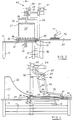
- Figure 1 is a plan of a device according to the invention,
- Figure 2 is a side elevation of the device of Figure 1 showing an early stage in the cycle of operation of the device,
- Figure 3 is an end elevation of the device of Figure 1,
- Figures 4, 5 and 6 are further side elevations of the device of Figure 1 showing different stages in operation of the device and
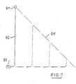
- Figure 7 is a diagram illustrating the mode of operation of a further device according to the invention.
- The device shown in the drawings is able to deposit a workpiece, constituted by a piece of flexible sheet material, in a desired location.
- The device comprises a
table top 10 supported onstanchions stanchions 12 are connected by twohorizontal beams 13. Mounted on thetable top 10 is amovable tray 14. Thetray 14 is supported bywheels wheels 15 run on thetable top 10 and thewheels 16, with axles lower than the axles of thewheels 15, run in aguide rail 17 so that thetray 14 is guided for reciprocal movement between an extended location for deposition of a workpiece, shown in Figures 1, 2 and 4, and a retracted location for the tray, shown in Figures 5 and 6. - Movement of the
tray 14 is effected by an air- operated piston-and-cylinder device 18 mounted onbrackets 19 beneath thetable top 10. Thepiston rod 21 of thedevice 18 is connected to thetray 14 by astrap 22 which extends through aslot 23 in thetable top 10. - At the leading edge of the
tray 14 in its movement from the retracted location of Figures 5 and 6 to the extended location of Figures 1, 2 and 4, anapron 24 is secured to the tray. Theapron 24 is inclined down towards thetable top 10 but terminates at a height spaced from the table top so as to remain clear of workpieces deposited on thetable top 10 when the tray passes over them during retraction from the position shown in Figures 1, 2 and 4. - In order to retain a workpiece above the desired location during a retraction of the
tray 14, a flexible sheet comprising ablanket 25 of synthetic rubber is used. In its rest position, theblanket 25 is supported on the concave upper surface of acurved metal plate 26 mounted on twopillars 27 upstanding from thetable top 10. The lower end of theplate 26 is secured to anupper strip 30 secured by bolts (not shown) to abar 28 extending close to and parallel to thetable top 10 and also parallel to anedge 29 of thetray 14 and at right angles to the direction of to-and-fro movement of thetray 14. An edge of theblanket 25 is clamped between thestrip 30 and thebar 28 which is secured on apillar 32 upstanding from thetable top 10 and asupport 33 secured to apillar 56 fixed to thebeams 13. - A
movable edge 35 of theblanket 25 is clamped between arod 36 and ashaped bar 37 by means of bolts (not shown) extending through the rod, blanket and bar, and securing them together. Thebar 37 is carried on anextension 38 of anarm 39 of apantograph 40 havingfurther arms arm 39. Thefourth arm 46 of the pantograph mechanism is pivotally connected to thearms arm 39. - An
extension 51 of thearm 42 is secured to acollar 52 fixed on anaxle 53 of a pneumaticrotary torque actuator 54. Thetorque actuator 54 is mounted on aplate 55 carried by thepillar 56 fixed to thebeams 13. Thepillar 56 carries near its upper end abracket 57 and anarm 58 of the pillar carries asimilar bracket 59. Theaxle 53 is mounted in bearings carried by thebrackets - Also secured to the
collar 52 is anarm 61 carrying acounter-balance weight 62. - A
sideways extension 63 from thearm 46 forming an inverted V-shape together with that arm (Figure 2) has acam follower 64 at its end and thecam follower 64 is engaged in acam track 65 formed in aplate 66 secured to thearm 58 of thepillar 56. The cam follower is shown at the upper end of thecam track 65 in Figure 2 and moving down the cam track from the position shown in Figure 2, the locus of thecam follower 65 is first ashallow curve 67 concave about theaxle 53. There follows astraight line portion 68 inclined downwardly at an angle less than 10° to the horizontal, and finally a shortstraight section 69 inclined downwardly at approximately 10° to the horizontal. - The
torque actuator 54 can be operated to rotate theaxle 53 either in a clockwise or an anti-clockwise direction. Starting from the position shown in Figure 2, anti-clockwise rotation of theaxle 53 will rotate thepantograph arm 42 anti-clockwise pushing thearm 39 in front of it. Thecam follower 64 following the cam track, will maintain thebar 37 at an approximately constant distance from theplate 26 during the initial part of the movement of theblanket 25 during which thecam follower 64 will traverse the firstshallow curve 67 of thecam track 65 and thebar 37 with theedge 35 of theblanket 25 will move near to theupper strip 30. - As the
bar 37 moves over thetray 14, thecam follower 64 will traverse the firststraight section 68, moving thebar 37 over thetray 14. Finally, thebar 37 will move down over theapron 24 whilst thecam follower 64 moves along the finalstraight section 69 of thecam track 65 and at this stage, theblanket 25 will have been rolled out over thetray 14 to the position shown in Figure 4. A strip ofsponge rubber 72 secured along therod 36 serves here to press the adjacent region of theblanket 25 against thetable top 10. - On operating the
torque actuator 54 to rotate theaxle 53 clockwise from the position shown in Figure 4, thepantograph 40 will be caused to retrace its path so that thebar 37 will carry theedge 35 of theblanket 25 back above thetray 14 and upwardly over theplate 26 to the position shown in Figure 2. Theedge 35 of theblanket 25 will be maintained always above thetray 14 or apron 24 at approximately a constant distance from theplate 26. - The operation of the device shown in the drawings will now be described with reference to Figures 2, 4, 5 and 6. Figure 2 shows the device in the starting position of a cycle of operations (except that in Figure 2, one
workpiece 78 is shown in the deposited position and one 75 is shown on the tray 14). - The first procedure in an operating cycle, with the
tray 14 in the position shown in Figure 2, is to place aworkpiece 75 in a flat opened-out condition in a predetermined position on atable top 34. A manipulator head 76 (Figure 3) carried by anarm 77 of a programmable manipulator (not shown) is then brought down on top of theworkpiece 75 and moves it onto thetray 14, which is at the same height as thetable top 34. This movement carries theworkpiece 75 to the desired location above thetable top 10. - The
blanket 25 is next lowered onto theworkpiece 75 to serve as retaining means to retain the workpiece above the desired location during retraction of thetray 14. Lowering of theblanket 25 is effected by operating thetorque actuator 54 to rotate theaxle 53 anti-clockwise in Figure 2. As thebar 37 descends, carrying with it theedge 35 of theblanket 25, the blanket is progressively pushed out over thetray 14 with an unrolling action of a foldedregion 78 of the blanket. Thus, a region of theblanket 25 makes initial contact with theworkpiece 75 and part of the blanket is then progressively lowered onto the workpiece so that contact between the workpiece and the blanket is progressively established starting at one region of the blanket and moving progressively across the blanket. The end of this part of the operating cycle is shown in Figure 4. - Next, the
tray 14 is retracted to the left in Figure 4 by operation of the piston-and-cylinder device 18 and the result of this movement of thetray 14 is shown in Figure 5. Theworkpiece 75 is retained in its desired position by theblanket 25 and is thus deposited in a desired location on thetable top 10 on top of, and with one of its edges aligned with an edge of, aprevious workpiece 78 deposited on the table top in a predetermined position in an earlier cycle of operation of the device. - Next, the
blanket 25 is retracted by operating thetorque actuator 54 to turn theaxle 53 in a clockwise direction and this leaves the twoworkpieces table top 10 in the desired position (Figure 6). The workpieces can now be moved together to the next stage of a garment assembly process by themanipulator head 76, as indicated by the arrow X in Figure 1. - The
table top 34, which has to be at the level of thetray 14 to allow aworkpiece 75 to be slid from the table top to the tray, may be mounted so that it can be raised and lowered so that with thetable top 34 lowered, a workpiece can be slid across another table top (not shown) at the level of thetable top 10 onto thetable top 34, thetable top 34 can then be raised to allow transfer (by sliding) of the workpiece to thetray 14 as part of the operating cycle described above. Such an arange- ment avoids any need for a change in the table levels such as that shown in the drawings, which may be inconvenient if in a garment assembly line, a number of workpiece depositing devices are required. - Figure 7 shows an alternative configuration for a flexible sheet in the form of a blanket 82 a lower edge of which is secured to a fixed
bar 83 and the upper edge of which is secured to amovable bar 84. A pantograph mechanism, similar to that shown in Figures 1 to 6, can be used to support and move thebar 84, but other mechanisms can also be used for this purpose. For example, thebar 84 may be supported by an arm or arms of a programmable manipulator. - The
locus 85 of thebar 84 in laying down theblanket 82 on a workpiece is indicated by a chain- dotted line in Figure 7, as are successive positions of theblanket 82. Contact between theblanket 82 and a workpiece beneath it is progressively established in a similar manner to that described above in relation to theblanket 25. - A blanket of relatively heavy weight construction is preferred and a solid commercial grade neoprene sheeting with a so-called « cloth finish of a thickness of 3.2 mm (1/8 "), a density of 1.6 gm/cm2 and a shore (or IRHD) hardness of 60170° has proved to be very satisfactory. A blanket of rubber elastic material with a density in the range 1.2 to 2.0 gm/cm2 would be preferred.
Claims (8)
Applications Claiming Priority (2)
| Application Number | Priority Date | Filing Date | Title |
|---|---|---|---|
| GB8500837 | 1985-01-14 | ||
| GB858500837A GB8500837D0 (en) | 1985-01-14 | 1985-01-14 | Laying-up workpieces of flexible sheet material |
Publications (2)
| Publication Number | Publication Date |
|---|---|
| EP0210211A1 EP0210211A1 (en) | 1987-02-04 |
| EP0210211B1 true EP0210211B1 (en) | 1989-01-11 |
Family
ID=10572795
Family Applications (1)
| Application Number | Title | Priority Date | Filing Date |
|---|---|---|---|
| EP86900796A Expired EP0210211B1 (en) | 1985-01-14 | 1986-01-13 | Laying-up workpieces of flexible sheet material |
Country Status (6)
| Country | Link |
|---|---|
| US (1) | US4708334A (en) |
| EP (1) | EP0210211B1 (en) |
| JP (1) | JPS62501373A (en) |
| DE (1) | DE3661678D1 (en) |
| GB (2) | GB8500837D0 (en) |
| WO (1) | WO1986003949A1 (en) |
Families Citing this family (2)
| Publication number | Priority date | Publication date | Assignee | Title |
|---|---|---|---|---|
| IT1213829B (en) * | 1987-09-22 | 1990-01-05 | Solis Srl | METHOD AND MACHINE FOR THE AUTOMATIC TRANSFER OF TIGHTS OR SIMILAR TUBULAR MANUFACTURES BETWEEN TWO GROUPS OF FINISHING MACHINES OF THESE MANUFACTURES |
| DE3819136A1 (en) * | 1988-06-06 | 1989-12-07 | Pfaff Ind Masch | SEWING UNIT WITH A TRANSPORT DEVICE |
Family Cites Families (9)
| Publication number | Priority date | Publication date | Assignee | Title |
|---|---|---|---|---|
| DE2138119C3 (en) * | 1970-08-10 | 1981-01-29 | Roeder & Spengler Ohg, 6000 Bergen- Enkheim | Device for stacking blanks or the like. Stackable |
| US3940125A (en) * | 1974-05-17 | 1976-02-24 | Cluett, Peabody & Co., Inc. | Picking and transporting means for fabric sections and the like |
| US3978785A (en) * | 1974-06-05 | 1976-09-07 | Multifold-International, Inc. | Stacking and bundling machine |
| US4176832A (en) * | 1976-05-26 | 1979-12-04 | Cluett, Peabody & Co., Inc. | Method and apparatus for handling, positioning and assembling fabric plies |
| US4159108A (en) * | 1977-12-08 | 1979-06-26 | Peter Haft | Garment stacker |
| DE3023533C2 (en) * | 1980-06-24 | 1982-11-25 | Bielomatik Leuze Gmbh + Co, 7442 Neuffen | Device for depositing sheets in a pile |
| JPS57182443A (en) * | 1981-05-08 | 1982-11-10 | Komori Printing Mach Co Ltd | Front guide device for sheet fed press |
| WO1986005466A1 (en) * | 1985-03-22 | 1986-09-25 | Pacific Dunlop Limited | Handling limp fabric |
| DE3666578D1 (en) * | 1985-03-22 | 1989-11-30 | Pacific Dunlop Ltd | Apparatus for handling limp fabric |
-
1985
- 1985-01-14 GB GB858500837A patent/GB8500837D0/en active Pending
-
1986
- 1986-01-13 GB GB08620578A patent/GB2182024B/en not_active Expired
- 1986-01-13 WO PCT/GB1986/000020 patent/WO1986003949A1/en not_active Ceased
- 1986-01-13 EP EP86900796A patent/EP0210211B1/en not_active Expired
- 1986-01-13 US US06/915,033 patent/US4708334A/en not_active Expired - Fee Related
- 1986-01-13 JP JP61500627A patent/JPS62501373A/en active Granted
- 1986-01-13 DE DE8686900796T patent/DE3661678D1/en not_active Expired
Also Published As
| Publication number | Publication date |
|---|---|
| US4708334A (en) | 1987-11-24 |
| JPH034648B2 (en) | 1991-01-23 |
| WO1986003949A1 (en) | 1986-07-17 |
| EP0210211A1 (en) | 1987-02-04 |
| DE3661678D1 (en) | 1989-02-16 |
| GB2182024B (en) | 1989-01-25 |
| GB8620578D0 (en) | 1986-10-01 |
| JPS62501373A (en) | 1987-06-04 |
| GB8500837D0 (en) | 1985-02-20 |
| GB2182024A (en) | 1987-05-07 |
Similar Documents
| Publication | Publication Date | Title |
|---|---|---|
| EP0329870B1 (en) | A device for transferring a lithographic plate | |
| US5096370A (en) | Device for the transfer of a part stack of material in sheet form from a general stack to a further-processing station | |
| US5256027A (en) | Lifting apparatus | |
| US4493412A (en) | Glass sheet positioning apparatus for conveyor platform | |
| EP0484373B1 (en) | Arrangement at press line | |
| US4658715A (en) | System for automating the palletizing of bundles | |
| CA1184434A (en) | Rail clip driving apparatus | |
| US3973673A (en) | Method and apparatus for turning over sheets | |
| US4708334A (en) | Laying-up workpieces of flexible sheet material | |
| EP0316038A2 (en) | Automatic loading unit for sheet units onto functional machines equipped with a conveyor | |
| US5158417A (en) | Gripping and manipulating means for receptacles of textile material | |
| US4421225A (en) | Material handling apparatus | |
| EP0274809B1 (en) | Apparatus for mounting power transmission belts on and removing same from pulleys | |
| US4565362A (en) | Transfer apparatus | |
| US4400841A (en) | Apparatus and method for handling sheet material | |
| US3533118A (en) | Loading bridge | |
| US4606274A (en) | Travelling railroad tie removal machine | |
| US4744716A (en) | Method and apparatus for transferring elongated objects | |
| CN215853946U (en) | Transfer mechanism of palletizing robot | |
| US20050211268A1 (en) | Plate-like element loading and unloading apparatus | |
| US4952203A (en) | Process and apparatus for pairing a front and rear panel of a t-shirt | |
| US3601264A (en) | Loading and unloading apparatus | |
| CA2097223A1 (en) | Unit for feeding semifinished parts to a forming machine, particularly a press | |
| CN217707767U (en) | Turnover device for box body | |
| CA1178809A (en) | Material handling apparatus |
Legal Events
| Date | Code | Title | Description |
|---|---|---|---|
| PUAI | Public reference made under article 153(3) epc to a published international application that has entered the european phase |
Free format text: ORIGINAL CODE: 0009012 |
|
| 17P | Request for examination filed |
Effective date: 19861101 |
|
| AK | Designated contracting states |
Kind code of ref document: A1 Designated state(s): DE FR IT |
|
| EL | Fr: translation of claims filed | ||
| DET | De: translation of patent claims | ||
| 17Q | First examination report despatched |
Effective date: 19880210 |
|
| GRAA | (expected) grant |
Free format text: ORIGINAL CODE: 0009210 |
|
| AK | Designated contracting states |
Kind code of ref document: B1 Designated state(s): DE FR IT |
|
| ITF | It: translation for a ep patent filed | ||
| REF | Corresponds to: |
Ref document number: 3661678 Country of ref document: DE Date of ref document: 19890216 |
|
| ET | Fr: translation filed | ||
| PLBE | No opposition filed within time limit |
Free format text: ORIGINAL CODE: 0009261 |
|
| STAA | Information on the status of an ep patent application or granted ep patent |
Free format text: STATUS: NO OPPOSITION FILED WITHIN TIME LIMIT |
|
| 26N | No opposition filed | ||
| PGFP | Annual fee paid to national office [announced via postgrant information from national office to epo] |
Ref country code: FR Payment date: 19901228 Year of fee payment: 6 |
|
| ITTA | It: last paid annual fee | ||
| PGFP | Annual fee paid to national office [announced via postgrant information from national office to epo] |
Ref country code: DE Payment date: 19910320 Year of fee payment: 6 |
|
| PG25 | Lapsed in a contracting state [announced via postgrant information from national office to epo] |
Ref country code: FR Effective date: 19920930 |
|
| PG25 | Lapsed in a contracting state [announced via postgrant information from national office to epo] |
Ref country code: DE Effective date: 19921001 |
|
| REG | Reference to a national code |
Ref country code: FR Ref legal event code: ST |
|
| PG25 | Lapsed in a contracting state [announced via postgrant information from national office to epo] |
Ref country code: IT Free format text: LAPSE BECAUSE OF NON-PAYMENT OF DUE FEES;WARNING: LAPSES OF ITALIAN PATENTS WITH EFFECTIVE DATE BEFORE 2007 MAY HAVE OCCURRED AT ANY TIME BEFORE 2007. THE CORRECT EFFECTIVE DATE MAY BE DIFFERENT FROM THE ONE RECORDED. Effective date: 20050113 |