EP0210080B1 - Verfahren und Einrichtung zur Bearbeitung eines hohlen Werkstückes durch Fräsung entlang einer vorbestimmten Linie - Google Patents
Verfahren und Einrichtung zur Bearbeitung eines hohlen Werkstückes durch Fräsung entlang einer vorbestimmten Linie Download PDFInfo
- Publication number
- EP0210080B1 EP0210080B1 EP86400962A EP86400962A EP0210080B1 EP 0210080 B1 EP0210080 B1 EP 0210080B1 EP 86400962 A EP86400962 A EP 86400962A EP 86400962 A EP86400962 A EP 86400962A EP 0210080 B1 EP0210080 B1 EP 0210080B1
- Authority
- EP
- European Patent Office
- Prior art keywords
- cutter
- axis
- tube
- real
- control means
- Prior art date
- Legal status (The legal status is an assumption and is not a legal conclusion. Google has not performed a legal analysis and makes no representation as to the accuracy of the status listed.)
- Expired - Lifetime
Links
Images





Classifications
-
- G—PHYSICS
- G05—CONTROLLING; REGULATING
- G05B—CONTROL OR REGULATING SYSTEMS IN GENERAL; FUNCTIONAL ELEMENTS OF SUCH SYSTEMS; MONITORING OR TESTING ARRANGEMENTS FOR SUCH SYSTEMS OR ELEMENTS
- G05B19/00—Program-control systems
- G05B19/02—Program-control systems electric
- G05B19/42—Recording and playback systems, i.e. in which the program is recorded from a cycle of operations, e.g. the cycle of operations being manually controlled, after which this record is played back on the same machine
- G05B19/425—Teaching successive positions by numerical control, i.e. commands being entered to control the positioning servo of the tool head or end effector
-
- B—PERFORMING OPERATIONS; TRANSPORTING
- B23—MACHINE TOOLS; METAL-WORKING NOT OTHERWISE PROVIDED FOR
- B23Q—DETAILS, COMPONENTS, OR ACCESSORIES FOR MACHINE TOOLS, e.g. ARRANGEMENTS FOR COPYING OR CONTROLLING; MACHINE TOOLS IN GENERAL CHARACTERISED BY THE CONSTRUCTION OF PARTICULAR DETAILS OR COMPONENTS; COMBINATIONS OR ASSOCIATIONS OF METAL-WORKING MACHINES, NOT DIRECTED TO A PARTICULAR RESULT
- B23Q15/00—Automatic control or regulation of feed movement, cutting velocity or position of tool or work
- B23Q15/007—Automatic control or regulation of feed movement, cutting velocity or position of tool or work while the tool acts upon the workpiece
- B23Q15/013—Control or regulation of feed movement
- B23Q15/02—Control or regulation of feed movement according to the instantaneous size and the required size of the workpiece acted upon
-
- G—PHYSICS
- G05—CONTROLLING; REGULATING
- G05B—CONTROL OR REGULATING SYSTEMS IN GENERAL; FUNCTIONAL ELEMENTS OF SUCH SYSTEMS; MONITORING OR TESTING ARRANGEMENTS FOR SUCH SYSTEMS OR ELEMENTS
- G05B2219/00—Program-control systems
- G05B2219/30—Nc systems
- G05B2219/37—Measurements
- G05B2219/37398—Thickness
-
- G—PHYSICS
- G05—CONTROLLING; REGULATING
- G05B—CONTROL OR REGULATING SYSTEMS IN GENERAL; FUNCTIONAL ELEMENTS OF SUCH SYSTEMS; MONITORING OR TESTING ARRANGEMENTS FOR SUCH SYSTEMS OR ELEMENTS
- G05B2219/00—Program-control systems
- G05B2219/30—Nc systems
- G05B2219/50—Machine tool, machine tool null till machine tool work handling
- G05B2219/50353—Tool, probe inclination, orientation to surface, posture, attitude
-
- Y—GENERAL TAGGING OF NEW TECHNOLOGICAL DEVELOPMENTS; GENERAL TAGGING OF CROSS-SECTIONAL TECHNOLOGIES SPANNING OVER SEVERAL SECTIONS OF THE IPC; TECHNICAL SUBJECTS COVERED BY FORMER USPC CROSS-REFERENCE ART COLLECTIONS [XRACs] AND DIGESTS
- Y10—TECHNICAL SUBJECTS COVERED BY FORMER USPC
- Y10T—TECHNICAL SUBJECTS COVERED BY FORMER US CLASSIFICATION
- Y10T29/00—Metal working
- Y10T29/49—Method of mechanical manufacture
- Y10T29/49764—Method of mechanical manufacture with testing or indicating
- Y10T29/49771—Quantitative measuring or gauging
-
- Y—GENERAL TAGGING OF NEW TECHNOLOGICAL DEVELOPMENTS; GENERAL TAGGING OF CROSS-SECTIONAL TECHNOLOGIES SPANNING OVER SEVERAL SECTIONS OF THE IPC; TECHNICAL SUBJECTS COVERED BY FORMER USPC CROSS-REFERENCE ART COLLECTIONS [XRACs] AND DIGESTS
- Y10—TECHNICAL SUBJECTS COVERED BY FORMER USPC
- Y10T—TECHNICAL SUBJECTS COVERED BY FORMER US CLASSIFICATION
- Y10T29/00—Metal working
- Y10T29/49—Method of mechanical manufacture
- Y10T29/49995—Shaping one-piece blank by removing material
- Y10T29/49996—Successive distinct removal operations
-
- Y—GENERAL TAGGING OF NEW TECHNOLOGICAL DEVELOPMENTS; GENERAL TAGGING OF CROSS-SECTIONAL TECHNOLOGIES SPANNING OVER SEVERAL SECTIONS OF THE IPC; TECHNICAL SUBJECTS COVERED BY FORMER USPC CROSS-REFERENCE ART COLLECTIONS [XRACs] AND DIGESTS
- Y10—TECHNICAL SUBJECTS COVERED BY FORMER USPC
- Y10T—TECHNICAL SUBJECTS COVERED BY FORMER US CLASSIFICATION
- Y10T409/00—Gear cutting, milling, or planing
- Y10T409/30—Milling
- Y10T409/30084—Milling with regulation of operation by templet, card, or other replaceable information supply
- Y10T409/30112—Process
-
- Y—GENERAL TAGGING OF NEW TECHNOLOGICAL DEVELOPMENTS; GENERAL TAGGING OF CROSS-SECTIONAL TECHNOLOGIES SPANNING OVER SEVERAL SECTIONS OF THE IPC; TECHNICAL SUBJECTS COVERED BY FORMER USPC CROSS-REFERENCE ART COLLECTIONS [XRACs] AND DIGESTS
- Y10—TECHNICAL SUBJECTS COVERED BY FORMER USPC
- Y10T—TECHNICAL SUBJECTS COVERED BY FORMER US CLASSIFICATION
- Y10T409/00—Gear cutting, milling, or planing
- Y10T409/30—Milling
- Y10T409/303752—Process
- Y10T409/303808—Process including infeeding
Definitions
- the present invention relates to a method of machining a hollow part by milling along a predetermined path, and more particularly the machining of a curved groove by milling in the wall of a cylindrical tube, as well as a installation allowing the implementation of this process.
- the milling of a hollow part is an operation which, in known manner, is carried out by conventional milling machines by skilled workers; in the case of a tube, this is generally carried by a mobile support which is moved during milling so that the worker can achieve the desired groove contour.
- the problem is further complicated in certain applications by the fact that the grooves must be dug with an extremely precise depth, since the fabric remaining at the bottom of the groove must have an extremely small thickness compared to the milling depth and the groove must in no case case lead inside the tube.
- the invention proposes to solve this problem.
- the process which is the subject of the invention which allows the machining of a hollow part by milling along a predetermined path relative to a theoretical surface thereof, by means of a cutter mounted in end of a drive shaft carried by a movable support orientable according to at least two degrees of freedom in tilting and at least one degree of freedom in translation, in which the quantity of material to be removed at a point on the layout is determined by a difference of setpoint between the underside of the cutter and an actual reference surface, internal surface or external surface of the part, is characterized in that it comprises:
- a machining step consisting in making the cutter again traverse the predetermined path, the position and orientation of the cutter being controlled so that, at each point of the sampling, the axis of the cutter forms a constant angle with respect to the normal to the real surface and to the direction tangent to the layout at this point, and the distance separating the underside of the cutter from the reference surface of the part is made equal to the setpoint deviation for this point.
- the document FR-A-1 537 084 describes the recognition of a machining path for a hollow part by mechanical probing of the external surface thereof. Besides that this method has the known drawbacks of any mechanical probing, namely a great influence of the wear of the probing means on the precision of the measurements and consequently of the machining to be carried out, which implies the need for corrections taking into account account for this wear, it in no way deals with questions of orientation of the machining tool which could however consist of a milling cutter.
- the reference surface is the interior surface of the part: this in particular when it is desired that a canvas of constant thickness remains at the bottom of the groove.
- the internal surface is determined by calculation, from a value of constant theoretical thickness in the direction normal to the real external surface of the part.
- the step of determining the interior surface of the part is a second recognition step, consisting in making the milling cutter traverse a second trajectory along which, at each point of the sampling, the cutter is positioned at a constant distance from the actual external surface of the part and with an orientation such that its axis coincides with the corresponding normal direction, then it is measured and stored, by means of an integrated depth sensor with the cutter, the thickness of the part, so as to determine the position of the internal surface of the part at this point. It is thus ensured that the thickness of the fabric will be constant whatever the external shape and whatever the effective thickness of the part.
- this method makes it possible to obtain a groove whose bottom (flat) is parallel to the zone of the internal wall of the tube which is opposite the groove, on the other side of the remaining fabric, and that '' by correctly controlling the penetration of the cutter, a constant fabric thickness can be obtained.
- the mobile support is rotated around the main axis with a variable radius; to obtain a closed contour groove whose shape is close to the circle, the movable support is rotated around the main axis by an angle at least equal to 360 °.
- the installation for machining a curved groove by milling in the wall of a cylindrical tube comprises: ⁇ A frame fixed relative to the tube, An armature guided in translation on the frame to slide in a direction perpendicular to the axis of the tube, ⁇ A plate guided in rotation on the frame to rotate around a main axis which is intersecting and perpendicular to the axis of the tube, ⁇ A carriage guided in translation on the plate to slide along a secant axis and perpendicular to the main axis, ⁇ A bracket articulated on the carriage to tilt around a secondary axis which is orthogonal to the sliding axis of the carriage, A cutter mounted at the end on a shaft which is guided in rotation in the articulated stirrup and whose axis is intersecting and perpendicular to the secondary axis, A means for controlling the movement of said armature on the fixed frame, A means for controlling the rotation of said plate on the frame, A means for controlling the movement of said
- This installation is preferably equipped with a memory computer which controls the control means in slaving with the movement of rotation of the plate around the main axis, so that the axis of the cutter is constantly substantially perpendicular at the wall of the tube, and that the penetration of the bur into the wall of the tube takes place in a controlled manner.
- each electrical axis is preferably provided with its own position sensor.
- the means for controlling the rotation of the plate and the tilting of the stirrup are advantageously electric motors with analog control, while the means for controlling the sliding of the frame and the sliding of the carriage are jacks and / or motors electric with numerical control.
- the installation is advantageously equipped with an optical fiber integrated in the cutter.
- the installation is advantageously equipped with an ultrasonic pad which is adapted to be mounted in end of the strawberry tree, in place of the latter.
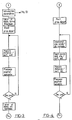
- FIGS. 1 and 2 illustrate the process of the invention in its most general aspect, the various stages being described by the flowcharts of FIGS. 3 to 5.
- the reference 1 designates the hollow workpiece (for example a cylindrical tube) and the reference 2 the mobile milling cutter with its integrated sensor located at the points designated B in Figure 1 and C in Figure 2.
- the structure of the cutter with its integrated sensor will be described below, with reference to FIG. 6.
- the operator introduces into a calculation system the various parameters necessary for machining: for example diameter and thickness of the tube, position and orientation of its axis, depth of the groove to be machined or thickness of the metal fabric to remain. From this various information, the computer determines and stores a theoretical shape of the surface to be machined, that is to say the ideal shape that it would have in the absence of any irregularity in shape or thickness. .
- the cutter with its integrated sensor is then positioned at a starting point, and the external surface is recognized on a sampling of points, the number of which depends on the precision desired for the measurement.
- This operation consists in measuring, at each point, the difference between the real external surface SR and the theoretical surface ST determined beforehand by the calculation.
- a first sweep trajectory TB1 defined with respect to the theoretical surface ST (for this is the only reference available at the start) is run through with a milling cutter, for example a trajectory at constant distance from the theoretical surface, l the axis of the cutter remaining constantly perpendicular to the normal to the theoretical surface (in the case of a cylindrical tube, this amounts to saying that the cutter moves on a coaxial cylinder with the theoretical, cylindrical surface, and enveloping it ).
- This constant distance is of course chosen so that the cutter never comes into contact with the actual external surface, taking into account the maximum value of the amplitude of the irregularities that can be expected.
- distances A onB1 .... A4B4 are thus measured which will be stored to constitute a representation of the real surface SR in the computer memory.
- the direction of the normal N to the real external surface at this point is also determined: in FIG. 1, we have indeed shown two types of deformation of the workpiece: at point A2, a defect in curvature so that the normal N to the external surface no longer intersects the axis O of the cylinder; at points A3 and A4, the direction of the normal is correct, but a slight offset of the corresponding portion of the cylinder ensures that the radius OA3 or OA4 is greater than the theoretical value provided (in the latter case, a milling taking into account the theoretical surface alone would cause the cutter to open into the interior of the tube, instead of leaving a thin sheet of metal).
- a second recognition step is then carried out, in accordance with the flow diagram of FIG. 4.
- the purpose of this step is to determine the actual internal surface of the tube, by means of an appropriate sensor integrated into the cutter or substituted for it. This sensor is for example a conventional type ultrasonic sensor, the echo analysis making it possible to know the exact thickness of the tube at the points measured.
- the cutter is subjected to a second scanning trajectory TB2, different from the first scanning trajectory TB1, defined as follows: at each point of the sampling defined for the previous step, the probe is oriented so that its axis is always coincident with the direction normal to the surface at this point (normal direction determined by the measurement, during the previous step); the probe is also moved so as to always be at a constant distance from the real external surface (as determined by the measurement, in the same way): in FIG. 2, this corresponds to distances A1C1, A2C2 .... A8C8 which are all equal; in the case of the positions of the probe M4 and M5, it can also be seen that the latter has been inclined so as to make up for the defect in curvature at points A4 and A5.
- the measurement of the thickness, and therefore the determination of the internal surface of the tube can be done under strictly constant measurement conditions - in particular by eliminating any parallax error.
- the orientation of the axis of the cutter is determined so as to form a constant angle with respect to the normal to the real surface and to the direction tangent to the layout: most often, it is simply to position the cutter with its axis coincident with the normal to the surface to be machined; in some cases it may however be desired that the axis of the cutter is inclined relative to the normal, in particular in the case of the machining of a chamfer.
- the position of the cutter is also adjusted so as to maintain a constant distance from the interior surface of the wall, as it is represented in memory in the computer from the results of the preceding recognition steps; this distance is equal to the thickness of the metal fabric which it is desired to leave at the bottom of the groove.
- Machining is thus continued throughout the course, with a permanent adjustment of the orientation of the cutter and its depth of penetration into the workpiece.
- FIG. 6 shows an example of a milling cutter, referenced 2, provided with an integrated optical sensor 100 making it possible to determine the difference existing between the real surface SR and the theoretical surface ST, according to the classic principle of optical triangulation: a light emission (coherent or not) is brought by means of an optical fiber 110 and focused by a lens 120 at a point A, corresponding to the position of the theoretical surface in the axis of the cutter (the distance AB between the theoretical surface and the underside of the cutter being, as indicated above, kept constant). The reflected light energy is received and focused by a lens 130 towards a deflection mirror 140 and a photoelectric detector 150.
- This photoelectric detector can be constituted for example by a strip of diodes, or in a simplified version, by a double photoelectric cell for a simple differential measurement.
- An electrical conductor 160 sends the received signal back to the installation computer.
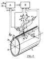
- Figure 7 shows the cylindrical tube 1, for example metallic, arranged horizontally with radius R0 and wall thickness E0.
- the radius R0 is for example between 50 and 500 mm while the thickness E0 is between 5 and 85 mm.
- the tube 1 which has been artificially cut in the drawing, constitutes a continuous pipe which is in place, in a fixed manner, on a site.
- the installation comprises the cutter 2, which is mounted at the end on a shaft 3, of axis X4, which is rotated by means of a motor M4.
- the shaft 3 is carried by a support (not shown in Figure 7 for clarification purposes) which is articulated on a carriage 5 (shown by a vertical segment).
- the carriage 5 is arranged to rotate around a vertical axis X1, which we will call the main axis, which cuts the horizontal axis X0 of the tube at a point I.
- the carriage 5 is offset laterally relative to the axis X1 d ' an adjustable distance.
- a motor M1 makes it possible to rotate the carriage around the main axis X1.
- a motor M2 makes it possible to modify the distance d2.
- the cutter 2, and its support, not shown, are articulated around an axis X3, which we will call secondary axis.
- This horizontal axis passes through the axis X4 of the cutter shaft 3 and is perpendicular to the plane formed by the axes X4 and X1.
- a motor Mclude makes it possible to tilt the cutter (and its support) around the axis X3.
- the assembly constituted by the carriage 5, the cutter support, and the cutter 2, is movable in vertical translation, parallel to the main axis X1.
- This movement is controlled by a motor or an electric cylinder M5.
- the installation includes a memory computer A arranged to drive the motors M1, M2, M3, M4 and M5, via a control interface B.
- the installation is equipped with a device for detecting and measuring the surface unevenness of the tube, which is connected to the computer A. It is an optical fiber housed coaxially in the cutter shaft 3 and in the cutter 2 and opening onto the front face thereof. This fiber is arranged to supply the computer, in a known manner, with information on the proximity of a surface to which it faces, in this case the surface of the tube.
- the installation is also equipped with a device for measuring the thickness of the wall of the tube, also connected to the computer A.
- This device comprises a pellet emitting and receiving ultrasound C, of known type, capable of providing to the computer, information on the thickness of a wall to which it faces, in this case the wall of the tube 1.
- the pellet C has a tail identical to that of the milling cutter 2, which authorizes its mounting at the end d tree 3.
- the installation is positioned above the tube, in line with the machining area provided, and data D0 and E0 are entered into the computer memory which correspond respectively to the theoretical diameter and thickness of the tube in this zone.
- the distance d2 is controlled by means of the motor M2, so that it corresponds to the radius r of the contour that one wishes to obtain.
- a first vacuum inspection phase is carried out, that is to say without machining, by making the milling cutter - which is not rotated - traverse a path corresponding to the contour r of the groove.
- This trajectory is governed by the different advances given to the motors M5 and M3, as a function of the rotation ⁇ 1 of the carriage 5 controlled by the motor M1.
- the control of the installation is carried out by the computer A, via the control interface B, as a function of the information previously stored in memory concerning the theoretical diameter D0 of the tube and its theoretical thickness E0. This control is defined in such a way that the front face of the cutter grazes the external wall of the tube, substantially parallel to the latter, without touching it.
- the optical fiber integrated into the cutter detects any surface unevenness of the tube wall, that is to say the dimensional differences compared to its theoretical profile, in particular bumps or hollows and ovalizations .
- the real radius R of the tube, a function of the angle ⁇ 1 of rotation of the carriage 5, is information which is stored in the calculator A.
- the computer A controls, via the interface B, the milling of the groove, by controlling the rotation of the carriage 5 around the main axis X1 and the advance of the motors M3 and M5 as a function of the angle of rotation ⁇ 1.
- This control which takes into account the real radius R ( ⁇ 1) of the tube and its effective thickness E ( ⁇ 1), is such that, on the one hand, the axis X4 of the cutter is substantially perpendicular to the external wall of the tube and that, on the other hand, its penetration into the wall takes place in a controlled manner,
- the starting position corresponds, for example, to a milling zone located on the upper generatrix of the tube
- the axis X4 of the cutter are then placed vertically, perpendicular to the axis X0 of the tube.
- the axis of the cutter is located radially, that is to say is intersecting and perpendicular to the axis X0 of the tube.
- the axis of the cutter again vertical; after three-quarters of a turn, it is again radial.
- the milling cutter is controlled by the computer so as to be substantially perpendicular to the external wall of the tube, so that the bottom of the groove is substantially parallel to the internal wall of the tube.
- controlled penetration means that the penetration of the cutter can be chosen, by prior programming of the computer, so that this penetration is constant or so that the remaining fabric, that is to say say the thickness separating the bottom of the groove from the internal wall of the tube, be constant.
- the machining is carried out on an angle ⁇ 1 at least equal to 360 °, for example on an angle of 365 °, so as to obtain a completely closed groove.
- Figures 8 to 11 show an embodiment of a machining installation for implementing the method which has just been described.
- the installation has the form of a gantry comprising a horizontal plate 10 and a pair of vertical columns 17 which are fixed to the tube to be machined 1 by means of suitable fixing flanges 18.
- the milling axis 3 is guided in rotation in a support 4 in the shape of a stirrup. It carries a conical coaxial pinion 12 engaged with a complementary pinion 13, the axis of which is arranged perpendicularly to the axis X4 of the shaft 3.
- the support 4 is articulated in the lower part, in the form of a yoke, of a carriage 5.
- the wings of this one yoke carries a motor M3 capable of tilting the support 4 around an axis X3 perpendicular to X4, and the other a motor M4 capable of driving the cutter 2 by means of the bevel gears 12, 13.
- the upper part of the carriage has the shape of a T arranged to slide in a horizontal slide 8 in dovetail formed in an approximately circular plate 6.
- the T-shaped portion of the carriage 5 is crossed by a tapped hole whose axis X2 is parallel to the slide 8 and into which a filtered rod 7 carried by the plate 6 penetrates.
- a motor M2 integral with the plate 6 is adapted to rotate the rod 7 in order to move the carriage 5 in the slide 8.
- the plate 6 is integral, in its center, with a vertical splined shaft 14 of axis X1 arranged to be driven in rotation, by means of pinions 15, 16, by a motor M1.
- the latter is fixed by means of a lug 11 to the frame plate 10.
- the rotation of the motor M1 controls the rotation of the plate 6, by means of the shaft 14, with the possibility of axial displacement of the latter.
- the plate 6 is guided in rotation on a frame 9, in the form of a horizontal plate, which is slidably mounted on the vertical columns 17.
- the sliding of the frame 9 is controlled by a motor or an electric actuator M5, by the intermediate a rod 19 of vertical axis X5.
- the radius of curvature d2 is first adjusted by means of the motor M2. Then, from the initial position in which the cutter 2 is in contact with the upper generator of the tube 1 (position in FIGS. 7 and 8), we do turn the plate 6 around the axis X1 by means of the motor M1.
- the median vertical axis Y of the carriage 5 will therefore describe a circular trajectory around X1.
- Control of the inclination of the axis X4 of the cutter during machining is obtained by starting, in one direction or another, the motor Mmount which controls the tilting of the caliper 4. It will be noted that the transmission, by bevel gears, of control of the cutter authorizes this tilting.
- Control of the penetration of the cutter into the wall of the tube is obtained by starting, in one direction or the other, of the motor M5 which causes the rise or fall of the frame 9 and all of the organs carried by it. During this movement, the rotation drive of the plate 6 remains possible thanks to the presence of the splined shaft 14 which meshes with the pinion 16 controlled by the motor M1.
Landscapes
- Engineering & Computer Science (AREA)
- Robotics (AREA)
- Physics & Mathematics (AREA)
- General Physics & Mathematics (AREA)
- Automation & Control Theory (AREA)
- Mechanical Engineering (AREA)
- Milling Processes (AREA)
- Turning (AREA)
- Electrical Discharge Machining, Electrochemical Machining, And Combined Machining (AREA)
Claims (17)
· einen ersten Verfahrensschritt zum Erkennen der äußeren Oberflache des Werkstücks, der darin besteht:
1. die Fräse eine erste Trajektorie (TB1) mit einem konstanten Abstand (A₁B₁...A₄B₄) von der theoretischen Oberfläche (ST) durchlaufen zu lassen, wobei dieser Abstand so ausgewählt ist, daß die Fräse nie mit dem Werkstück in Berührung kommt, und
2. Meßwerte für eine Reihe von Punkten auf der Linie aufzunehmen,
2.1 indem mittels eines in der Fräse integrierten Aufnehmers (100) der Abstand zwischen der unteren Seite der Fräse und der äußeren, re ellen Oberfläche des Werkstücks In der Achse der Fräse gemessen und gespeichert wird und indem der relative Abstand (△ x) zwischen der reellen und der theoretischen Oberfläche in jedem vermessenen Punkt bestimmt wird.
2.2 indem ausgehend von in jedem Meßpunkt gemessenen Abstand und von den in den angrenzenden Punkten gemessenen Abständen die Richtung der Normalen (N) zur äußeron, reellen Oberfläche in jedem Meßpunkt bestimmt und gespeichert wird,
· einen Bearbeitungsschritt, der darin besteht, die Fräse erneut die vorgegebene Linie durchlaufen zu lassen, wobei die Position und Ausrichtung der Fräse so gesteuert werden, daß in jedem Meßpunkt die Fräsenachse einen konstanten Winkel bezüglich der Normalen der reellen Oberfläche und bezüglich der Richtung der Tangente zur Linie in diesem Punkt bildet und daß der Abstand zwischen der Unterseite der Fräse von der Referenzoberfläche des Werkstücks gleich dem Einstellabstand für diesen Punkt ist.
· einer Orehung um eine Hauptachse (X₁), die die Achse (X₀) des Rohrs schneidet und dazu senkrecht ist,
· ein Kippen um eine sekundäre Achse (X₃), die die Achse (X₄) der Fräse schneidet und senkrecht zur Ebene steht, die von der letzteren mit der Hauptachse (X₁ ) gebildet wird,
· eine Translation entlang einer Richtung parallel zur Hauptachse (X₁),
wobei die beiden letzteren Bewegungen so mit der ersten gesteuert werden, daß die Achse (X₄) der Fräse konstant im wesentlichen senkrecht zur Rohrwand ist und daß die Eindringtiefe der Fräse in die Rohrwand konstant gesteuert wird.
· ein auf dem und bezüglich des Rohres festes Gestell (17, 18, 10),
· eine in Translationsrichtung zum Gleiten entlang einer Richtung senkrecht zur Rohrachse (X₀) auf dem Gestell geführte Bewehrung (9),
· eine in Drehrichtung auf dem Gestell zum Drehen um eine Hauptachse (X₁), die die Rohrachse (X₀) schneidet und senkrecht darauf steht, geführte Platte (6),
· einen in Translationsrichtung auf der Platte (6) zum Gleiten entlang einer Achse (X₂), die die Hauptachse (X₁) schneidet und senkrecht darauf steht, geführten Wagen (5),
· einen gelenkig auf dem Wagen zum Kippen um eine sekurdäre Achse (X₃),die senkrecht zur Gleitachse (X₂) des Wagens ist, befestigten Bügel (4),
· eine am Ende einer Motorwelle (3) montierte Fräse (2), die n der Drehung von dem gelenkig verbundenen Bügel (4) geführt wird und deren Achse (X₄) die sekundäre Achse (X₃) schneidet und dazu senkrecht ist,
· eine Steuerungsvorrichtung (M₅) für die Bewegung der Bewehrung (9) auf dem festen Gestel,
· eine Steuervorrichtung (M₁) für die Drehung der Platte (6) auf der Bewehrung,
· eine Steuervorrichtung (M₂) für die Bewogung des Wagens (5) auf der Platte,
· eine Steuervorrichtung (M₃) für das Kippen des Bügels (4) um die sekundäre Achse (X₃),
· eine Steuervorrichtung (M₄) für die Drehung der Fräse (2) um ihre Achse (X₄).
17. Bearbeitungsvorrichtung nach Anspruch 16, dadurch gekennzeichnet, daß die Meßvorrichtung ein Ultraschallplättchen (C) umfaßt, das geeignet ist, am Ende der Fräsenwelle (3) an deren Stelle montiert zu werden.
Priority Applications (1)
| Application Number | Priority Date | Filing Date | Title |
|---|---|---|---|
| AT86400962T ATE59712T1 (de) | 1985-05-06 | 1986-05-02 | Verfahren und einrichtung zur bearbeitung eines hohlen werkstueckes durch fraesung entlang einer vorbestimmten linie. |
Applications Claiming Priority (2)
| Application Number | Priority Date | Filing Date | Title |
|---|---|---|---|
| FR8506838 | 1985-05-06 | ||
| FR8506838A FR2581334B1 (fr) | 1985-05-06 | 1985-05-06 | Procede et installation d'usinage d'une piece creuse par fraisage le long d'un trace predetermine |
Publications (2)
| Publication Number | Publication Date |
|---|---|
| EP0210080A1 EP0210080A1 (de) | 1987-01-28 |
| EP0210080B1 true EP0210080B1 (de) | 1991-01-02 |
Family
ID=9318979
Family Applications (1)
| Application Number | Title | Priority Date | Filing Date |
|---|---|---|---|
| EP86400962A Expired - Lifetime EP0210080B1 (de) | 1985-05-06 | 1986-05-02 | Verfahren und Einrichtung zur Bearbeitung eines hohlen Werkstückes durch Fräsung entlang einer vorbestimmten Linie |
Country Status (6)
| Country | Link |
|---|---|
| US (1) | US4786219A (de) |
| EP (1) | EP0210080B1 (de) |
| AT (1) | ATE59712T1 (de) |
| CA (1) | CA1268976A (de) |
| DE (1) | DE3676371D1 (de) |
| FR (1) | FR2581334B1 (de) |
Families Citing this family (20)
| Publication number | Priority date | Publication date | Assignee | Title |
|---|---|---|---|---|
| GB2206513B (en) * | 1987-07-08 | 1991-11-06 | Amada Co Ltd | V-shaped groove forming machine and its control method |
| GB8809160D0 (en) * | 1988-04-19 | 1988-05-25 | Renishaw Plc | Co-ordinate measuring machine |
| US5744776A (en) * | 1989-07-14 | 1998-04-28 | Tip Engineering Group, Inc. | Apparatus and for laser preweakening an automotive trim cover for an air bag deployment opening |
| US5246655A (en) * | 1991-04-30 | 1993-09-21 | The Young Industries, Inc. | Method of making thermoplastic valve rotors |
| US5185917A (en) * | 1991-07-22 | 1993-02-16 | Gennady Kremen | Method of machining keyways in shafts |
| US5288209A (en) * | 1991-12-19 | 1994-02-22 | General Electric Company | Automatic adaptive sculptured machining |
| US5788435A (en) * | 1995-04-28 | 1998-08-04 | Mccarthy; John F. | Automated diamond cutter apparatus |
| US5808888A (en) * | 1996-01-11 | 1998-09-15 | Thermwood Corporation | Method and apparatus for programming a CNC machine |
| US5857897A (en) * | 1997-09-23 | 1999-01-12 | General Motors Corporation | Method for machining an "O" ring retention groove into a curved surface |
| US6049982A (en) * | 1998-05-22 | 2000-04-18 | Tseng; Shao-Chien | Integrated molding method for the front fork of a bicycle |
| AU3504100A (en) * | 1999-03-10 | 2000-09-28 | Titan Specialties, Ltd. | Scalloped gun body with improved tolerances for underground well perforating, and process of manufacturing the same |
| GB2363861A (en) * | 2000-06-19 | 2002-01-09 | Robotic Technology Systems Plc | Processing an object, eg a workpiece, by a tool |
| US7464630B2 (en) * | 2001-08-27 | 2008-12-16 | Flow International Corporation | Apparatus for generating and manipulating a high-pressure fluid jet |
| FI117327B (fi) * | 2004-03-26 | 2006-09-15 | T Drill Oy | Laite soikean reiän työstämiseksi putken seinämään |
| WO2007046737A1 (en) * | 2005-10-21 | 2007-04-26 | Volvo Aero Corporation | A method and device for controlling a tool with ultrasonic waves |
| US9242303B2 (en) * | 2010-05-03 | 2016-01-26 | National Oilwell Varco, L.P. | Cutting device on moveable platform |
| US20120046777A1 (en) * | 2010-08-19 | 2012-02-23 | Imhoff Jamie L | Integrated machining and part inspection method |
| FR3071180B1 (fr) * | 2017-09-20 | 2019-11-08 | Eurl Usiplace 39 | Dispositif de rectification. |
| CN114719707B (zh) * | 2022-06-07 | 2022-09-13 | 中国科学院西安光学精密机械研究所 | 基于投影轨迹复原的柱体柱面槽线精度检测装置及方法 |
| CN115847182B (zh) * | 2022-11-30 | 2025-03-18 | 北京星航机电装备有限公司 | 中空零件的内置轴向平行平面的定位方法 |
Family Cites Families (7)
| Publication number | Priority date | Publication date | Assignee | Title |
|---|---|---|---|---|
| FR1537084A (fr) * | 1967-07-10 | 1968-08-23 | Commissariat Energie Atomique | Procédé d'usinage d'une pièce, notamment tubulaire, à épaisseur prédéterminée |
| US4384332A (en) * | 1979-10-23 | 1983-05-17 | Renishaw Electrical Limited | Numerically controlled machine tool |
| JPS57156183A (en) * | 1981-03-20 | 1982-09-27 | Hitachi Ltd | Method and device for controlling course of robot |
| US4492847A (en) * | 1981-09-30 | 1985-01-08 | Unimation, Inc. | Manipulator welding apparatus with sensing arrangements for weld slam tracking |
| JPS58206364A (ja) * | 1982-05-24 | 1983-12-01 | Toshiba Mach Co Ltd | 工作機械 |
| JPS58208807A (ja) * | 1982-05-31 | 1983-12-05 | Nissan Motor Co Ltd | ロボツトのテイ−チング装置 |
| US4598380A (en) * | 1984-08-13 | 1986-07-01 | Cincinnati Milacron Inc. | Method and apparatus for controlling manipulator and workpiece positioner |
-
1985
- 1985-05-06 FR FR8506838A patent/FR2581334B1/fr not_active Expired
-
1986
- 1986-05-02 DE DE8686400962T patent/DE3676371D1/de not_active Expired - Lifetime
- 1986-05-02 AT AT86400962T patent/ATE59712T1/de not_active IP Right Cessation
- 1986-05-02 EP EP86400962A patent/EP0210080B1/de not_active Expired - Lifetime
- 1986-05-05 US US06/859,649 patent/US4786219A/en not_active Expired - Fee Related
- 1986-05-06 CA CA000508438A patent/CA1268976A/fr not_active Expired - Lifetime
Also Published As
| Publication number | Publication date |
|---|---|
| ATE59712T1 (de) | 1991-01-15 |
| FR2581334B1 (fr) | 1987-12-31 |
| CA1268976A (fr) | 1990-05-15 |
| DE3676371D1 (de) | 1991-02-07 |
| EP0210080A1 (de) | 1987-01-28 |
| FR2581334A1 (fr) | 1986-11-07 |
| US4786219A (en) | 1988-11-22 |
Similar Documents
| Publication | Publication Date | Title |
|---|---|---|
| EP0210080A1 (de) | Verfahren und Einrichtung zur Bearbeitung eines hohlen Werkstückes durch Fräsung entlang einer vorbestimmten Linie | |
| EP0290546B1 (de) | Werkstückträgerspindel mit magnetischen lagern und vorrichtung zum verwenden dieser in einer hochpräzisen werkzeugmaschinen | |
| EP0141717A2 (de) | Positioniereinrichtung für Roboter | |
| FR2681546A1 (fr) | Procede et machine d'usinage a commande numerique multi-axe. | |
| EP0216695B1 (de) | Verfahren und Maschine zur Herstellung von Rotationshohlkörpern aus in drei verschiedenen Richtungen verlaufenden Gespinstfasern | |
| FR2664042A1 (fr) | Controleur de dimension de spot pour un appareil de prise de vues a profondeur de champ variable. | |
| EP0289575B1 (de) | Verfahren zur ultra-präzisen bearbeitung von untypischen rotationsflächen und selbststeuernde bearbeitung | |
| WO1997013614A1 (fr) | Dispositif de mesure ou de controle de l'usinage d'une piece cylindrique a mouvement orbital | |
| EP0074453A1 (de) | Verfahren und Maschine zur Herstellung von Schraubennahtröhren aus Karton, und Röhren auf diese Art hergestellt | |
| WO1990012277A1 (fr) | Procede et dispositif de mesurage profilometrique de large echelle et leurs applications a la mesure de l'etat de surfaces de forme quelconque | |
| CA1211029A (fr) | Machine a scie annulaire pour le tronconnage de tubes | |
| EP0377374B1 (de) | Messsystem für eine Werkzeugeinstellung in einer Werkzeugmaschine | |
| FR2562829A1 (fr) | Dispositif de commande de relevage et de translation du chariot d'une machine a deborder et a biseauter les verres de lunettes | |
| EP0247939B1 (de) | Maschine zur automatischen Regelung von Länge und Durchmesser eines Werkzeuges | |
| EP0036374A1 (de) | Verfahren und Vorrichtung zum Schweissen mit automatischem Folgen der Schweissnaht | |
| EP0707201B1 (de) | Laserstrahlanalysator | |
| FR2575955A1 (fr) | Procede et installation pour la rectification et le controle du diametre d'une meule | |
| EP0478439B1 (de) | Maschine zur Herstellung von geschliffenen Schrauben ausgehend von Stäben | |
| EP0043741B1 (de) | Bearbeitungsverfahren für variable Rotationsflächen und numerisch gesteuerte Werkzeugmaschine zu Bearbeitung solcher Oberflächen | |
| FR2694836A1 (fr) | Dispositif de contrôle des éléments de guidage d'un tube-guide des équipements internes supérieurs d'un réacteur nucléaire à eau sous pression. | |
| EP0098758A2 (de) | Verfahren und Vorrichtung zum Steuern und Überwachen der Stellung einer Lichtbogenschweisseinrichtung zwischen zwei Schweisskanten | |
| WO2007060304A2 (fr) | Methode d'etalonnage d'une meuleuse et dispositif correspondant | |
| EP0057131A1 (de) | Werkzeugpositions- und Arbeitsgeschwindigkeitsservoapparat | |
| EP1963066A1 (de) | Verfahren zur kalibrierung einer optischen glasbohrmaschine | |
| FR2503943A1 (fr) | Machine a usiner les entre-lames de collecteurs et produits similaires |
Legal Events
| Date | Code | Title | Description |
|---|---|---|---|
| PUAI | Public reference made under article 153(3) epc to a published international application that has entered the european phase |
Free format text: ORIGINAL CODE: 0009012 |
|
| AK | Designated contracting states |
Kind code of ref document: A1 Designated state(s): AT BE CH DE GB IT LI LU NL SE |
|
| RIN1 | Information on inventor provided before grant (corrected) |
Inventor name: LEMARQUIS, JEAN-CLAUDE Inventor name: OBERLIN, CLAUDE Inventor name: DOLHEN, GERARD Inventor name: MORAND, PHILIPPE |
|
| 17P | Request for examination filed |
Effective date: 19870421 |
|
| 17Q | First examination report despatched |
Effective date: 19890713 |
|
| GRAA | (expected) grant |
Free format text: ORIGINAL CODE: 0009210 |
|
| AK | Designated contracting states |
Kind code of ref document: B1 Designated state(s): AT BE CH DE GB IT LI LU NL SE |
|
| PG25 | Lapsed in a contracting state [announced via postgrant information from national office to epo] |
Ref country code: IT Free format text: LAPSE BECAUSE OF FAILURE TO SUBMIT A TRANSLATION OF THE DESCRIPTION OR TO PAY THE FEE WITHIN THE PRESCRIBED TIME-LIMIT;WARNING: LAPSES OF ITALIAN PATENTS WITH EFFECTIVE DATE BEFORE 2007 MAY HAVE OCCURRED AT ANY TIME BEFORE 2007. THE CORRECT EFFECTIVE DATE MAY BE DIFFERENT FROM THE ONE RECORDED. Effective date: 19910102 Ref country code: NL Effective date: 19910102 Ref country code: AT Effective date: 19910102 |
|
| REF | Corresponds to: |
Ref document number: 59712 Country of ref document: AT Date of ref document: 19910115 Kind code of ref document: T |
|
| GBT | Gb: translation of ep patent filed (gb section 77(6)(a)/1977) | ||
| REF | Corresponds to: |
Ref document number: 3676371 Country of ref document: DE Date of ref document: 19910207 |
|
| PG25 | Lapsed in a contracting state [announced via postgrant information from national office to epo] |
Ref country code: CH Effective date: 19910531 Ref country code: LI Effective date: 19910531 Ref country code: LU Free format text: LAPSE BECAUSE OF NON-PAYMENT OF DUE FEES Effective date: 19910531 |
|
| NLV1 | Nl: lapsed or annulled due to failure to fulfill the requirements of art. 29p and 29m of the patents act | ||
| PLBE | No opposition filed within time limit |
Free format text: ORIGINAL CODE: 0009261 |
|
| STAA | Information on the status of an ep patent application or granted ep patent |
Free format text: STATUS: NO OPPOSITION FILED WITHIN TIME LIMIT |
|
| 26N | No opposition filed | ||
| REG | Reference to a national code |
Ref country code: CH Ref legal event code: PL |
|
| PGFP | Annual fee paid to national office [announced via postgrant information from national office to epo] |
Ref country code: GB Payment date: 19930427 Year of fee payment: 8 |
|
| PGFP | Annual fee paid to national office [announced via postgrant information from national office to epo] |
Ref country code: DE Payment date: 19930527 Year of fee payment: 8 Ref country code: SE Payment date: 19930527 Year of fee payment: 8 |
|
| PGFP | Annual fee paid to national office [announced via postgrant information from national office to epo] |
Ref country code: BE Payment date: 19930614 Year of fee payment: 8 |
|
| PG25 | Lapsed in a contracting state [announced via postgrant information from national office to epo] |
Ref country code: GB Effective date: 19940502 |
|
| PG25 | Lapsed in a contracting state [announced via postgrant information from national office to epo] |
Ref country code: SE Effective date: 19940503 |
|
| PG25 | Lapsed in a contracting state [announced via postgrant information from national office to epo] |
Ref country code: BE Effective date: 19940531 |
|
| BERE | Be: lapsed |
Owner name: ELECTRICITE DE FRANCE SERVICE NATIONAL Effective date: 19940531 |
|
| GBPC | Gb: european patent ceased through non-payment of renewal fee |
Effective date: 19940502 |
|
| EUG | Se: european patent has lapsed |
Ref document number: 86400962.6 Effective date: 19941210 |
|
| PG25 | Lapsed in a contracting state [announced via postgrant information from national office to epo] |
Ref country code: DE Effective date: 19950201 |
|
| EUG | Se: european patent has lapsed |
Ref document number: 86400962.6 |