EP0209898B1 - Film-flow packing - Google Patents
Film-flow packing Download PDFInfo
- Publication number
- EP0209898B1 EP0209898B1 EP86110126A EP86110126A EP0209898B1 EP 0209898 B1 EP0209898 B1 EP 0209898B1 EP 86110126 A EP86110126 A EP 86110126A EP 86110126 A EP86110126 A EP 86110126A EP 0209898 B1 EP0209898 B1 EP 0209898B1
- Authority
- EP
- European Patent Office
- Prior art keywords
- packing
- cooling sheets
- channels
- cooling
- sheets
- Prior art date
- Legal status (The legal status is an assumption and is not a legal conclusion. Google has not performed a legal analysis and makes no representation as to the accuracy of the status listed.)
- Expired - Lifetime
Links
- 238000012856 packing Methods 0.000 title claims abstract description 60
- 238000001816 cooling Methods 0.000 claims abstract description 87
- 239000007788 liquid Substances 0.000 claims abstract description 16
- 239000012530 fluid Substances 0.000 claims abstract description 8
- 238000007872 degassing Methods 0.000 claims abstract description 4
- 230000001154 acute effect Effects 0.000 claims description 2
- 239000000463 material Substances 0.000 claims description 2
- 239000003795 chemical substances by application Substances 0.000 description 6
- XLYOFNOQVPJJNP-UHFFFAOYSA-N water Substances O XLYOFNOQVPJJNP-UHFFFAOYSA-N 0.000 description 4
- 230000003068 static effect Effects 0.000 description 3
- 238000004026 adhesive bonding Methods 0.000 description 2
- 230000008878 coupling Effects 0.000 description 2
- 238000010168 coupling process Methods 0.000 description 2
- 238000005859 coupling reaction Methods 0.000 description 2
- 238000000151 deposition Methods 0.000 description 2
- 230000008021 deposition Effects 0.000 description 2
- 239000012535 impurity Substances 0.000 description 2
- 230000003993 interaction Effects 0.000 description 2
- 125000006850 spacer group Chemical group 0.000 description 2
- 230000008901 benefit Effects 0.000 description 1
- 230000008859 change Effects 0.000 description 1
- 238000005516 engineering process Methods 0.000 description 1
- 238000000605 extraction Methods 0.000 description 1
- 230000002349 favourable effect Effects 0.000 description 1
- 239000011888 foil Substances 0.000 description 1
- 230000006872 improvement Effects 0.000 description 1
- 230000001788 irregular Effects 0.000 description 1
- 238000000034 method Methods 0.000 description 1
- 239000004033 plastic Substances 0.000 description 1
- 229920003023 plastic Polymers 0.000 description 1
- 230000008569 process Effects 0.000 description 1
- 230000001737 promoting effect Effects 0.000 description 1
- 239000007921 spray Substances 0.000 description 1
- 238000005507 spraying Methods 0.000 description 1
Images



Classifications
-
- B—PERFORMING OPERATIONS; TRANSPORTING
- B01—PHYSICAL OR CHEMICAL PROCESSES OR APPARATUS IN GENERAL
- B01J—CHEMICAL OR PHYSICAL PROCESSES, e.g. CATALYSIS OR COLLOID CHEMISTRY; THEIR RELEVANT APPARATUS
- B01J19/00—Chemical, physical or physico-chemical processes in general; Their relevant apparatus
- B01J19/32—Packing elements in the form of grids or built-up elements for forming a unit or module inside the apparatus for mass or heat transfer
-
- F—MECHANICAL ENGINEERING; LIGHTING; HEATING; WEAPONS; BLASTING
- F28—HEAT EXCHANGE IN GENERAL
- F28F—DETAILS OF HEAT-EXCHANGE AND HEAT-TRANSFER APPARATUS, OF GENERAL APPLICATION
- F28F25/00—Component parts of trickle coolers
- F28F25/02—Component parts of trickle coolers for distributing, circulating, and accumulating liquid
- F28F25/08—Splashing boards or grids, e.g. for converting liquid sprays into liquid films; Elements or beds for increasing the area of the contact surface
- F28F25/087—Vertical or inclined sheets; Supports or spacers
-
- B—PERFORMING OPERATIONS; TRANSPORTING
- B01—PHYSICAL OR CHEMICAL PROCESSES OR APPARATUS IN GENERAL
- B01J—CHEMICAL OR PHYSICAL PROCESSES, e.g. CATALYSIS OR COLLOID CHEMISTRY; THEIR RELEVANT APPARATUS
- B01J2219/00—Chemical, physical or physico-chemical processes in general; Their relevant apparatus
- B01J2219/32—Details relating to packing elements in the form of grids or built-up elements for forming a unit of module inside the apparatus for mass or heat transfer
- B01J2219/322—Basic shape of the elements
- B01J2219/32203—Sheets
- B01J2219/3221—Corrugated sheets
-
- B—PERFORMING OPERATIONS; TRANSPORTING
- B01—PHYSICAL OR CHEMICAL PROCESSES OR APPARATUS IN GENERAL
- B01J—CHEMICAL OR PHYSICAL PROCESSES, e.g. CATALYSIS OR COLLOID CHEMISTRY; THEIR RELEVANT APPARATUS
- B01J2219/00—Chemical, physical or physico-chemical processes in general; Their relevant apparatus
- B01J2219/32—Details relating to packing elements in the form of grids or built-up elements for forming a unit of module inside the apparatus for mass or heat transfer
- B01J2219/322—Basic shape of the elements
- B01J2219/32203—Sheets
- B01J2219/32213—Plurality of essentially parallel sheets
- B01J2219/3222—Plurality of essentially parallel sheets with sheets having corrugations which intersect at an angle different from 90 degrees
-
- B—PERFORMING OPERATIONS; TRANSPORTING
- B01—PHYSICAL OR CHEMICAL PROCESSES OR APPARATUS IN GENERAL
- B01J—CHEMICAL OR PHYSICAL PROCESSES, e.g. CATALYSIS OR COLLOID CHEMISTRY; THEIR RELEVANT APPARATUS
- B01J2219/00—Chemical, physical or physico-chemical processes in general; Their relevant apparatus
- B01J2219/32—Details relating to packing elements in the form of grids or built-up elements for forming a unit of module inside the apparatus for mass or heat transfer
- B01J2219/322—Basic shape of the elements
- B01J2219/32203—Sheets
- B01J2219/32224—Sheets characterised by the orientation of the sheet
- B01J2219/32227—Vertical orientation
-
- B—PERFORMING OPERATIONS; TRANSPORTING
- B01—PHYSICAL OR CHEMICAL PROCESSES OR APPARATUS IN GENERAL
- B01J—CHEMICAL OR PHYSICAL PROCESSES, e.g. CATALYSIS OR COLLOID CHEMISTRY; THEIR RELEVANT APPARATUS
- B01J2219/00—Chemical, physical or physico-chemical processes in general; Their relevant apparatus
- B01J2219/32—Details relating to packing elements in the form of grids or built-up elements for forming a unit of module inside the apparatus for mass or heat transfer
- B01J2219/322—Basic shape of the elements
- B01J2219/32203—Sheets
- B01J2219/32248—Sheets comprising areas that are raised or sunken from the plane of the sheet
- B01J2219/32251—Dimples, bossages, protrusions
-
- B—PERFORMING OPERATIONS; TRANSPORTING
- B01—PHYSICAL OR CHEMICAL PROCESSES OR APPARATUS IN GENERAL
- B01J—CHEMICAL OR PHYSICAL PROCESSES, e.g. CATALYSIS OR COLLOID CHEMISTRY; THEIR RELEVANT APPARATUS
- B01J2219/00—Chemical, physical or physico-chemical processes in general; Their relevant apparatus
- B01J2219/32—Details relating to packing elements in the form of grids or built-up elements for forming a unit of module inside the apparatus for mass or heat transfer
- B01J2219/324—Composition or microstructure of the elements
- B01J2219/32483—Plastics
Definitions
- This invention relates to film-flow packings for apparatus for performing heat- and material- exchanges between a liquid and a gaseous medium, particularly for cooling towers and degassing units, comprising juxtaposed contiguous cooling sheets with fluid conducting open channels from top edge to bottom edge, following protracted sinuous lines in the form of undulations having parallel medial lines, mutually opposite open channels of a pair of adjacent cooling sheets being mutually offset along the medial lines while, in a projection at right angle to the cooling sheets, the open channels cross and form a system of interconnected passages.
- Such a packing is known from EP-A-0 115 455.
- Film-flow packings are, usually, composed of juxtaposed cooling sheets with medium conducting open channels having parallel medial lines.
- medial line is used to denote the principal direction of a channel.
- the cooling sheets occupy practically vertical positions.
- a liquid such as water is brought into the cooling sheets from above e.g. by means of spray nozzles.
- the liquid is, as it were, spread out by the channels of the cooling sheets and, thus, contacts a gaseous medium such as air flowing upwardly or in transverse direction between the cooling sheets at relatively large surface areas.
- EP-A-0 115 455 discloses packings with no discharge sections at all. Here entering agents strike directly against the edges of slant open channels without any baffling. Consequently, flow resistance caused by turbulence is even greater than in the former case.
- EP-A-0 038 913 discloses a packing for a heat exchanger in which improved turbulent flow is obtained. There is no suggestion of promoting laminar flow at inflow and outflow locations.
- the object of the present invention is to modify the flow conditions at such places so as to render the inflow and outflow of the interacting agents laminar rather than turbulent.
- the film-flow packing initially defined is characterised in that: at top and bottom edges in each pair of adjacent cooling sheets the open channels terminate in straight discharge channel sections and the cooling sheets occupy relative positions in which the straight discharge channel sections of the open channels in a pair of adjacent cooling sheets are in register with one another whereby individual closed discharge passages parallel to the medial lines are formed and are separated from one another and from the side edges of the cooling sheets by plane support surface areas at which adjacent cooling sheets abut against one another and are mutually fixed.
- the film-packing according to the invention is distinguished, in addition to low flow resistance at its discharge extremities, also by relatively high rigidity of structure, all due to the closed and straight discharge channel sections which ensure, on the one hand, substantially laminar flow at the entry and the exit of fluids and, on the other hand, large contacting surface areas for mutual fixing and support of juxtaposed contiguous cooling sheets.
- the cooling sheets may be subdivided into groups which are separated from one another by strut plates extending beyond the cooling sheets.
- the groups may form blocks superposed one above the other with gaps therebetween while the cooling sheets are arranged edgewise in the direction of superposition. Moreover, subsequent blocks are angularly displaced by 90° with respect to one another.
- Fig. 1 illustrates a packing consisting, for sake of simplicity, but of four cooling sheets 20a, 20b, 20c and 20d. Obviously, the number of cooling sheets may be different from what is shown in Fig. 1 as is known in the art.
- the cooling sheets 20a, 20b, 20c and 20d are flatwise juxtaposed and are, in a manner known perse, provided with open channels 26a, 26b, 26c and 26d arranged in the same principal direction 24.
- pairs of adjacent open channels on one side of the cooling sheets enclose open channels on the other side thereof.
- each cooling sheet is channelled on both its sides as indicated by reference numeral 26b in case of cooling sheet 20b. It is always mutually opposite open channels which are decisive for the operation of the packings, e.g. open channels 26a of cooling sheet 20a facing channels 26b of cooling sheet 20b since they jointly form passages for the passing of flowing media.
- Continuous sinuous lines 28a indicate open channels in a front cooling sheet facing a rear cooling sheet while broken sinuous lines 28b indicate open channels in the rear cooling sheet and facing the front cooling sheet.
- both patterns differ from each other in that in case of Fig. 2 the sinuous lines have separate medial lines 30 and, therefore, the crests of line 28b are in back to back relation with the troughs of line 28a, or vice versa.
- the medial lines 30 coincide or register with one another so that the sinuous lines of mutually opposite open channels meet at their base points where the lines 28a and 28b intersect with their medial lines 30.
- the points of meeting represent crossings 32 the significance of which has already been referred to and will be further explained hereinafter.
- the patterns of channel arrangements according to Figs. 2 and 3 are characteristic of cases where sinuous lines 28a and 28b of mutually opposite open channels are shifted with respect to one another by half cycles which means reverse relative positions.
- the crossings 32 yield, in addition to well definable couplings between channels, the possibility of evenly distributed point-like glueings.
- the former expedient enhances uniform load distribution.
- the latter permits to obtain self-contained packings suitable to withstand manipulation loads even in case of packings composed of very thin cooling sheets.
- channel arrangement patterns with mutual shifts of other than half cycle values may be employed as well in which case mutually opposite open channels are shifted with respect to one another by a fractional value of half cycles. Even such, as it were, irregular mutual shifts permit couplings of the sinuous lines and, thereby, crossings of channels as can easily be proved on basis of Figs. 2 and 3. However, inconveniences as regards design work and technology have to be reckoned with.
- Figs. 4 to 6 show a pair of adjacent cooling sheets 20a and 20b with open channels 26a and 26b, respectively, arranged according to the pattern illustrated in Fig. 2.
- Fig. 4 sections of the sinuous lines 28a and 28b of the open channels have been represented as well which permits to exactly designate the channel crossings 32.
- the open channels have discharge sections 36 which are parallel to the principal direction 24 of the channels 26a and 26b or, what is equivalent thereto, to their medial lines 30.
- discharge sections 36 permit laminar inflow and outflow of interacting agents that is a relatively low flow resistance at reaching and leaving the packing.
- the angle enclosed, on the one hand, by the tangents 34to the sinuous lines 28a and 28b of the open channels 26a and 26b, respectively, and, on the other hand, by their medial lines 30 is smaller than 45°.
- it will be an acute angle of about 25° such as the angle alpha in Figs. 2 and 3.
- the sinuous lines 28a and 28b are, on the one hand, sufficiently arcuate or bulging to permit their crossings and, on the other hand, protracted enough to prevent depositions of impurities.
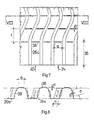
- Figs. 7 and 8 show an embodiment which constitutes an improvement of the cooling sheet 20a illustrated in Figs. 4 to 6 in that its open channels 26a are provided with ridges 38 in their walls.
- the ridges 38 are transverse of the principal direction 24 of the open channels and, thus, of their medial lines 30 indicated in Figs. 2 and 3. They are destined to cease the flow of laminar nature of an agent introduced in the direction of arrow 40 by tearing up its boundary layers and, thereby, to produce a turbulent flow in the arcuate sections of the open channels to enhance mixing.
- the walls of the discharge sections 36 have, in the present case, smooth surfaces since here a laminar flow may, for reasons already stated, be preferable.
- the open channels 26a have cross-sectional areas in the shape of protracted trapezoids as goes forth from Fig. 8.
- Both the oblique side walls of the open channels and their bottom portions which are parallel to the plane of the cooling sheet 20a are provided with ridges 38.
- Length a and spacing t of the ridges 38 are likewise multiples of the width b and height c thereof. Obviously, length a will be in concordance with the place at disposal.
- the ridges 38 in the bottom portions of the open channels 26a are shorter than the ridges in their oblique walls.
- the open channels may have cross-sectional areas of other than trapezoidal shape, e.g. semicircular or rectangular cross-sectional areas may be selected as well.
- the ridges are arcuate. If, in the latter case, the open channels are relatively narrow, preferably but the side walls will be provided with ridges.
- the packings are the more effective the larger the useful surface per unit volume.
- the latter is, among other things, the largerthethinner the cooling sheets since then relatively more cooling sheets can be located within a given volume.
- the resistance of the packing against gas flow is relatively smaller.
- the thickness of the cooling sheets of the packings will preferably amount to 0.1 to 0.8 millimeters. If the cooling sheets are made of very thin plastics sheets of a thickness such as 0.1 to 0.3 millimeters,the packing is easily liable to damages during handling and mounting operations. In order to exclude such undesired possibilities the cooling sheets will preferably be subdivided into groups and separated from one another by strut plates which, on all sides, extend beyond the cooling sheets.
- FIG. 9 An embodiment with groups of cooling sheets and strut plates between the groups is illustrated in Figs. 9 and 10.
- the packing 22 (Fig. 9) is composed of cooling sheets 20 which form three groups I, and III each comprising preferably 10 to 15 cooling sheets.
- the groups I, and III are separated from one another by strut plates 42 made of relatively thicker material. Both extremities of the packing 22 are closed also by such strut plates 42.
- the thickness of the strut plates 42 is a multiple of the thickness v2 of the cooling sheets 20, preferably they are 2 to 5 times as thick. Thus, e.g. in case of cooling sheets 20 of a thickness of 0.3 millimeter the thickness of the strut plates 42 will amount to 0.6 to 1.5 millimeters. Also the width and length of the strut plates 42 are greater than those of the cooling sheets 20 so that they reach beyond the latter by 5 to 10 millimeters as indicated by reference numerals 44 and 46 in Fig. 10. The advantage of such overhangs 44 and 46 consists in that the cooling sheets 20 are exempt from static loads in whatever positions of the packing 22 since it is always the strut plates 42 which are responsible for the support of the packing.
- the groups I, II and III are held together by through bolts 48 traversing the strut plates 42. Mutual distances of the latter are fixed by spacer sleeves 50 on the through bolts 48.
- the groups of cooling sheets can be connected with their strut plates by means of glueing in which case the packing represents a cemented block of cooling sheets and strut plates.
- the packing may, e.g. for the purpose of increased efficiency or for constructional reasons, consist of superposed blocks of cooling sheets in the manner of a column.
- a reason of constructional nature may be exemplified by blocks of cooling sheets which have open channels representing one complete cycle of a sinuous line only. Then, packings with open channels having a desired number of complete cycles may be obtained by superimposing a suitable number of blocks the cooling sheets of each of which have open channels of one cycle long only. Such expedient permits to build a wide range of packings out of prefabricated uniform elements.
- a packing 22 composed of a pair of superimposed blocks 52a and 52b is illustrated in Figs. 11 and 12.
- the blocks 52a and 52b are supported by strut plates 42 so that the edgewise positioned cooling sheets 20 are relieved from static loads here as well.
- the cooling sheets 20 of the blocks 52a and 52b are separated from one another by gaps 54 which permits a liquid leaving an upper block to spread out prior to entering a subsequent block. Thereby, a more uniform mixing with a gaseous medium flowing in counter current with the liquid will be obtained.
- Such effective mixing may even be improved if the superimposed blocks 52a and 52b are angularly displaced by an angle of 90° with respect to one another around a vertical axis of the column of superimposed blocks in which case the gaps 54 are automatically ensured by mutually abutting strut plates 42 as has relady been mentioned. Then, films of a liquid discharged from the upper block 52b are, in addition to being spread out in the gap 54, forced to enter between the cooling sheets 20 of the lower block 52a with a sharp change of orientation by which, again, mixing of the interacting agents is considerably enhanced.
- a liquid such as water is discharged from spraying nozzles (not shown) above the packings 22 into channels of its cooling sheets 20 and advances thereon in the form of films. Meanwhile, laminar flow with possibly low flow resistance in the straight discharge sections 36 where the channels are closed is transformed into turbulent flow in the sinuously shaped channels.
- a gaseous medium e.g. air
- both agents meet in the packing 22, an interaction therebetween takes place.
- the gaseous medium takes over a portion of the heat and vapours of the liquid and leaves the packing 22 in upward direction while its turbulent flow is retransformed into laminar flow.
- the liquid with possible absorbed portions of the gaseous medium is discharged at the bottom of the packing 22 in a similar manner. Due to such heat- and material-exchange the liquid is cooled down and the gaseous medium is warmed up as is known from the operation of e.g. conventional cooling towers.
Landscapes
- Engineering & Computer Science (AREA)
- Thermal Sciences (AREA)
- Chemical & Material Sciences (AREA)
- Physics & Mathematics (AREA)
- Mechanical Engineering (AREA)
- Chemical Kinetics & Catalysis (AREA)
- Organic Chemistry (AREA)
- General Engineering & Computer Science (AREA)
- Physical Or Chemical Processes And Apparatus (AREA)
- Preparation Of Clay, And Manufacture Of Mixtures Containing Clay Or Cement (AREA)
- Paper (AREA)
- Farming Of Fish And Shellfish (AREA)
- Cooling Or The Like Of Electrical Apparatus (AREA)
Abstract
Description
- This invention relates to film-flow packings for apparatus for performing heat- and material- exchanges between a liquid and a gaseous medium, particularly for cooling towers and degassing units, comprising juxtaposed contiguous cooling sheets with fluid conducting open channels from top edge to bottom edge, following protracted sinuous lines in the form of undulations having parallel medial lines, mutually opposite open channels of a pair of adjacent cooling sheets being mutually offset along the medial lines while, in a projection at right angle to the cooling sheets, the open channels cross and form a system of interconnected passages. Such a packing is known from EP-A-0 115 455.
- Such exchange occurs e.g. in cooling towers where water and air meet each other in counter-or cross-flow while heat and vapour of the water are partly taken over by the air. In principle, a similar process is taking place in degassing units where, however, removal of gas contained by the liquid is aimed at rather than extraction of its heat. In both cases, the basic principle of operation consists in providing a possibly large contact surface for the interacting media which is obtained by units known in the art as film-flow packings.
- Film-flow packings are, usually, composed of juxtaposed cooling sheets with medium conducting open channels having parallel medial lines. As will be seen, the term "medial line" is used to denote the principal direction of a channel. In operation, the cooling sheets occupy practically vertical positions. A liquid such as water is brought into the cooling sheets from above e.g. by means of spray nozzles. The liquid is, as it were, spread out by the channels of the cooling sheets and, thus, contacts a gaseous medium such as air flowing upwardly or in transverse direction between the cooling sheets at relatively large surface areas.
- The art knows of packings the channels of which follow zigzag lines composed of straight sections. Such packings are disclosed e.g. in GB-A-1 221 073. Zigzag lines, however, represent sharp directional changes at which possible impurities contained by a downwardly flowing liquid may stick and settle. Such depositions may gradually obstruct the packing and entail a rapid increase of its air resistance which, eventually, impairs operability.
- It has been proposed to avoid such difficulties by employing channels of sinuous or arcuate shape as described e.g. in EP-A-0 115 455.
- Such curvature of the channels is indispensable if cloggings have to be avoided. However, there are places in the packing where flow resistance is caused to appear without gaining anything thereby. Such places are where interacting fluids enter into and withdraw from the packing, respectively. With the known film-flow packings entries and exits of fluids were, as it seems, unheeded places of turbulence causing considerable increases of flow resistance without any use as to the performance of cooling. For instance, the cooling sheets of the packings described in the above mentioned GB-A-1 221 073 have straight or flat surfaces at their upper and lower ends by which incoming and withdrawing fluid streams undergo some baffling before and after their courses in intermediate packing portions. However, the cooling sheets of the known device are mutually distanced and, thus, the rooms between their flat terminal surfaces are common to all channels which means vigorous turbulence of fluids entering into or withdrawing from the packing. On the other hand, the aforesaid EP-A-0 115 455 discloses packings with no discharge sections at all. Here entering agents strike directly against the edges of slant open channels without any baffling. Consequently, flow resistance caused by turbulence is even greater than in the former case. EP-A-0 038 913 discloses a packing for a heat exchanger in which improved turbulent flow is obtained. There is no suggestion of promoting laminar flow at inflow and outflow locations.
- The object of the present invention is to modify the flow conditions at such places so as to render the inflow and outflow of the interacting agents laminar rather than turbulent.
- According to the invention, the film-flow packing initially defined is characterised in that: at top and bottom edges in each pair of adjacent cooling sheets the open channels terminate in straight discharge channel sections and the cooling sheets occupy relative positions in which the straight discharge channel sections of the open channels in a pair of adjacent cooling sheets are in register with one another whereby individual closed discharge passages parallel to the medial lines are formed and are separated from one another and from the side edges of the cooling sheets by plane support surface areas at which adjacent cooling sheets abut against one another and are mutually fixed.
- Thus, the film-packing according to the invention is distinguished, in addition to low flow resistance at its discharge extremities, also by relatively high rigidity of structure, all due to the closed and straight discharge channel sections which ensure, on the one hand, substantially laminar flow at the entry and the exit of fluids and, on the other hand, large contacting surface areas for mutual fixing and support of juxtaposed contiguous cooling sheets.
- Within a packing the cooling sheets may be subdivided into groups which are separated from one another by strut plates extending beyond the cooling sheets. By such arrangement vertically disposed cooling sheets will obviously be relieved from static loads so that they may be made of very thin foils which favours useful surface per unit volume. The groups may form blocks superposed one above the other with gaps therebetween while the cooling sheets are arranged edgewise in the direction of superposition. Moreover, subsequent blocks are angularly displaced by 90° with respect to one another.
- With such arrangement the gaps are automatically ensured by the strut plates of different blocks abutting crosswise against one another.
- Hereinafter the invention will be described by way of example in greater detail by making reference to the accompanying drawings in which:
- Fig. 1 is a perspective view of a packing with typical features;
- Fig. 2 illustrates a pattern characteristic of an arrangement of channels;
- Fig. 3 represents a further pattern of channel arrangement;
- Fig. 4 shows a front-elevational view of a pair of adjacent cooling sheets of an exemplified packing embodying the invention;
- Fig. 5 is a sectional view taken along line V-V of Fig. 4;
- Fig. 6 illustrates a sectional view taken along line VI-VI of Fig. 4;
- Fig. 7 represents a front-elevational view of a detail of a cooling sheet;
- Fig. 8 shows a sectional view taken along line VIII-VIII of Fig. 7;
- Fig. 9 is a front-elevational view of a further exemplified embodiment of the packing according to the invention;
- Fig. 10 illustrates a side-elevational view in accordance with Fig. 9;
- Fig. 11 represents a front-elevational view of still another exemplified embodiment of the packing according to the invention; and
- Fig. 12 shows a sectional view taken along line XII-XII of Fig. 11.
- Same reference numerals designate similar details throughout the drawings.
- Fig. 1 illustrates a packing consisting, for sake of simplicity, but of four
cooling sheets - The
cooling sheets open channels principal direction 24. As will be seen, pairs of adjacent open channels on one side of the cooling sheets enclose open channels on the other side thereof. Thus, each cooling sheet is channelled on both its sides as indicated byreference numeral 26b in case ofcooling sheet 20b. It is always mutually opposite open channels which are decisive for the operation of the packings, e.g.open channels 26a ofcooling sheet 20a facing channels 26b ofcooling sheet 20b since they jointly form passages for the passing of flowing media. - Mutually opposite open channels such as
open channels 26a ofcooling sheet 20a andopen channels 26b ofcooling sheet 26b are offset with respect to one another in theprincipal direction 24. - Due to such offset mutual positions the open channels intersect if viewed in a projection at right angle to the cooling sheets. This will be appreciated on the basis of Figs. 2 and 3 which show the pattern of channel arrangement in a pair of adjacent cooling sheets.
- Continuous
sinuous lines 28a indicate open channels in a front cooling sheet facing a rear cooling sheet while brokensinuous lines 28b indicate open channels in the rear cooling sheet and facing the front cooling sheet. - Both patterns differ from each other in that in case of Fig. 2 the sinuous lines have separate
medial lines 30 and, therefore, the crests ofline 28b are in back to back relation with the troughs ofline 28a, or vice versa. In contrast, with the arrangement shown in Fig. 3, themedial lines 30 coincide or register with one another so that the sinuous lines of mutually opposite open channels meet at their base points where thelines medial lines 30. In a projection at right angle to the cooling sheets the points of meeting representcrossings 32 the significance of which has already been referred to and will be further explained hereinafter. - It will be appreciated that the patterns of channel arrangements according to Figs. 2 and 3 are characteristic of cases where
sinuous lines crossings 32 yield, in addition to well definable couplings between channels, the possibility of evenly distributed point-like glueings. The former expedient enhances uniform load distribution. The latter permits to obtain self-contained packings suitable to withstand manipulation loads even in case of packings composed of very thin cooling sheets. - Obviously, channel arrangement patterns with mutual shifts of other than half cycle values may be employed as well in which case mutually opposite open channels are shifted with respect to one another by a fractional value of half cycles. Even such, as it were, irregular mutual shifts permit couplings of the sinuous lines and, thereby, crossings of channels as can easily be proved on basis of Figs. 2 and 3. However, inconveniences as regards design work and technology have to be reckoned with.
- Figs. 4 to 6 show a pair of
adjacent cooling sheets open channels sinuous lines channel crossings 32. - It will be seen that by means of their
crossings 32 thechannels open channels - With the embodiment shown in Figs. 4 to 6 the open channels have
discharge sections 36 which are parallel to theprincipal direction 24 of thechannels medial lines 30. As has been mentioned, such discharge sections permit laminar inflow and outflow of interacting agents that is a relatively low flow resistance at reaching and leaving the packing. - The angle enclosed, on the one hand, by the tangents 34to the
sinuous lines open channels medial lines 30 is smaller than 45°. Preferably, it will be an acute angle of about 25° such as the angle alpha in Figs. 2 and 3. At such values of the angle alpha thesinuous lines - Figs. 7 and 8 show an embodiment which constitutes an improvement of the
cooling sheet 20a illustrated in Figs. 4 to 6 in that itsopen channels 26a are provided withridges 38 in their walls. Theridges 38 are transverse of theprincipal direction 24 of the open channels and, thus, of theirmedial lines 30 indicated in Figs. 2 and 3. They are destined to cease the flow of laminar nature of an agent introduced in the direction of arrow 40 by tearing up its boundary layers and, thereby, to produce a turbulent flow in the arcuate sections of the open channels to enhance mixing. It will be appreciated that the walls of thedischarge sections 36 have, in the present case, smooth surfaces since here a laminar flow may, for reasons already stated, be preferable. - With the represented embodiment the
open channels 26a have cross-sectional areas in the shape of protracted trapezoids as goes forth from Fig. 8. Both the oblique side walls of the open channels and their bottom portions which are parallel to the plane of thecooling sheet 20a are provided withridges 38. Length a and spacing t of theridges 38 are likewise multiples of the width b and height c thereof. Obviously, length a will be in concordance with the place at disposal. Thus, in the present case, theridges 38 in the bottom portions of theopen channels 26a are shorter than the ridges in their oblique walls. - However, the open channels may have cross-sectional areas of other than trapezoidal shape, e.g. semicircular or rectangular cross-sectional areas may be selected as well. In the former case also the ridges are arcuate. If, in the latter case, the open channels are relatively narrow, preferably but the side walls will be provided with ridges.
- As is known, the packings are the more effective the larger the useful surface per unit volume. The latter is, among other things, the largerthethinner the cooling sheets since then relatively more cooling sheets can be located within a given volume. On the other hand, in case of thin cooling sheets also the resistance of the packing against gas flow is relatively smaller.
- The thickness of the cooling sheets of the packings will preferably amount to 0.1 to 0.8 millimeters. If the cooling sheets are made of very thin plastics sheets of a thickness such as 0.1 to 0.3 millimeters,the packing is easily liable to damages during handling and mounting operations. In order to exclude such undesired possibilities the cooling sheets will preferably be subdivided into groups and separated from one another by strut plates which, on all sides, extend beyond the cooling sheets.
- An embodiment with groups of cooling sheets and strut plates between the groups is illustrated in Figs. 9 and 10. With the represented embodi- mentthe packing 22 (Fig. 9) is composed of cooling
sheets 20 which form three groups I, and III each comprising preferably 10 to 15 cooling sheets. The groups I, and III are separated from one another bystrut plates 42 made of relatively thicker material. Both extremities of the packing 22 are closed also bysuch strut plates 42. - The thickness of the
strut plates 42 is a multiple of the thickness v2 of thecooling sheets 20, preferably they are 2 to 5 times as thick. Thus, e.g. in case of coolingsheets 20 of a thickness of 0.3 millimeter the thickness of thestrut plates 42 will amount to 0.6 to 1.5 millimeters. Also the width and length of thestrut plates 42 are greater than those of thecooling sheets 20 so that they reach beyond the latter by 5 to 10 millimeters as indicated byreference numerals such overhangs cooling sheets 20 are exempt from static loads in whatever positions of the packing 22 since it is always thestrut plates 42 which are responsible for the support of the packing. - With the represented embodiment the groups I, II and III are held together by through
bolts 48 traversing thestrut plates 42. Mutual distances of the latter are fixed byspacer sleeves 50 on the throughbolts 48. However, instead of bolts and spacers the groups of cooling sheets can be connected with their strut plates by means of glueing in which case the packing represents a cemented block of cooling sheets and strut plates. - Furthermore, the packing may, e.g. for the purpose of increased efficiency or for constructional reasons, consist of superposed blocks of cooling sheets in the manner of a column. A reason of constructional nature may be exemplified by blocks of cooling sheets which have open channels representing one complete cycle of a sinuous line only. Then, packings with open channels having a desired number of complete cycles may be obtained by superimposing a suitable number of blocks the cooling sheets of each of which have open channels of one cycle long only. Such expedient permits to build a wide range of packings out of prefabricated uniform elements.
- A packing 22 composed of a pair of superimposed
blocks 52a and 52b is illustrated in Figs. 11 and 12. As will be seen, theblocks 52a and 52b are supported bystrut plates 42 so that the edgewise positioned coolingsheets 20 are relieved from static loads here as well. Moreover, thecooling sheets 20 of theblocks 52a and 52b are separated from one another bygaps 54 which permits a liquid leaving an upper block to spread out prior to entering a subsequent block. Thereby, a more uniform mixing with a gaseous medium flowing in counter current with the liquid will be obtained. - Such effective mixing may even be improved if the superimposed
blocks 52a and 52b are angularly displaced by an angle of 90° with respect to one another around a vertical axis of the column of superimposed blocks in which case thegaps 54 are automatically ensured by mutuallyabutting strut plates 42 as has relady been mentioned. Then, films of a liquid discharged from the upper block 52b are, in addition to being spread out in thegap 54, forced to enter between the coolingsheets 20 of thelower block 52a with a sharp change of orientation by which, again, mixing of the interacting agents is considerably enhanced. - On the basis of what has been explained hereinbefore, operation of the packings does not seem to need detailed description.
- A liquid such as water is discharged from spraying nozzles (not shown) above the
packings 22 into channels of itscooling sheets 20 and advances thereon in the form of films. Meanwhile, laminar flow with possibly low flow resistance in thestraight discharge sections 36 where the channels are closed is transformed into turbulent flow in the sinuously shaped channels. At the same time, a gaseous medium, e.g. air, enters the packing 22 from below in a similar manner and flows upwards between the coolingsheets 20. As both agents meet in the packing 22, an interaction therebetween takes place. In the course of such interaction the gaseous medium takes over a portion of the heat and vapours of the liquid and leaves the packing 22 in upward direction while its turbulent flow is retransformed into laminar flow. The liquid with possible absorbed portions of the gaseous medium is discharged at the bottom of the packing 22 in a similar manner. Due to such heat- and material-exchange the liquid is cooled down and the gaseous medium is warmed up as is known from the operation of e.g. conventional cooling towers.
Claims (8)
Priority Applications (1)
| Application Number | Priority Date | Filing Date | Title |
|---|---|---|---|
| AT86110126T ATE49293T1 (en) | 1985-07-23 | 1986-07-23 | PACKING FOR FLOWING FLOW. |
Applications Claiming Priority (2)
| Application Number | Priority Date | Filing Date | Title |
|---|---|---|---|
| HU279685 | 1985-07-23 | ||
| HU852796A HU195314B (en) | 1985-07-23 | 1985-07-23 | Cooling insert for equipments carrying out heat and material exchange being between gaseous medium and fluid particularly for cooling towers and degasing units |
Publications (2)
| Publication Number | Publication Date |
|---|---|
| EP0209898A1 EP0209898A1 (en) | 1987-01-28 |
| EP0209898B1 true EP0209898B1 (en) | 1990-01-03 |
Family
ID=10961134
Family Applications (1)
| Application Number | Title | Priority Date | Filing Date |
|---|---|---|---|
| EP86110126A Expired - Lifetime EP0209898B1 (en) | 1985-07-23 | 1986-07-23 | Film-flow packing |
Country Status (4)
| Country | Link |
|---|---|
| EP (1) | EP0209898B1 (en) |
| AT (1) | ATE49293T1 (en) |
| DE (1) | DE3668056D1 (en) |
| HU (1) | HU195314B (en) |
Cited By (5)
| Publication number | Priority date | Publication date | Assignee | Title |
|---|---|---|---|---|
| EP0390765A1 (en) * | 1989-03-29 | 1990-10-03 | Hamon-Sobelco S.A. | Splashing boards resistant to biofouling |
| EP0394718A1 (en) * | 1989-04-07 | 1990-10-31 | Balcke-Dürr AG | Trickle insert |
| EP0554471A1 (en) * | 1992-02-01 | 1993-08-11 | 2H KUNSTSTOFF GmbH | Packing element for heat- or mass exchanger or bioreactor system |
| EP0745825A3 (en) * | 1995-05-31 | 1997-11-05 | BDAG Balcke-Dürr Aktiengesellschaft | Splashing element |
| AU710140B2 (en) * | 1995-06-27 | 1999-09-16 | Boc Group, Inc., The | Structured packing |
Families Citing this family (9)
| Publication number | Priority date | Publication date | Assignee | Title |
|---|---|---|---|---|
| US6101841A (en) † | 1998-10-02 | 2000-08-15 | Praxair Technology, Inc. | Cryogenic rectification system with high strength and high capacity packing |
| DE10001694A1 (en) * | 2000-01-18 | 2001-07-19 | Montz Gmbh Julius | Packing for heat- and mass exchange columns includes ridges making defined angles at their extremities, with top and bottom, horizontal panel edges |
| NL1019357C1 (en) * | 2001-11-13 | 2003-05-14 | J A Niemeijer B V | Filling package and biological cleaning agents provided with such a filling package. |
| US8685961B2 (en) | 2006-03-29 | 2014-04-01 | Merck Sharp & Dohme Corp. | Diazepan orexin receptor antagonists |
| EP2230011B1 (en) * | 2009-03-18 | 2020-03-25 | Sulzer Management AG | Structured packing |
| JP5727327B2 (en) * | 2011-08-08 | 2015-06-03 | 株式会社神戸製鋼所 | Heat exchanger |
| FR3020135A1 (en) * | 2014-04-16 | 2015-10-23 | Commissariat Energie Atomique | HEAT EXCHANGER MODULE WITH IMPROVED THERMAL EXCHANGE AND COMPACITY, USE WITH LIQUID METAL AND GAS. |
| CN113164907B (en) * | 2018-11-27 | 2022-10-04 | 布伦特伍德工业公司 | Filling sheet and related filling package assembly |
| CN113398852B (en) * | 2021-06-21 | 2023-03-28 | 许昌学院 | Inner temperature adjusting device of plate tower |
Family Cites Families (16)
| Publication number | Priority date | Publication date | Assignee | Title |
|---|---|---|---|---|
| BE493097A (en) * | 1949-07-06 | |||
| GB1080991A (en) * | 1963-03-04 | 1967-08-31 | Ici Ltd | Improvements in or relating to film-flow packins |
| SE307964B (en) * | 1964-03-24 | 1969-01-27 | C Munters | |
| SE311371B (en) * | 1966-01-26 | 1969-06-09 | Munters C | |
| GB1170940A (en) * | 1966-12-30 | 1969-11-19 | Industrieprojektierung Leipzig | Contact Heat Exchange Units for Cooling Towers. |
| GB1221073A (en) * | 1968-02-02 | 1971-02-03 | Nippon Kokan Kk | Improvements in and relating to gas-liquid contact systems and to plate elements of such systems |
| US3442494A (en) * | 1968-02-16 | 1969-05-06 | Baltimore Aircoil Co Inc | Evaporative heat exchange apparatus |
| CH583584A5 (en) * | 1972-10-18 | 1977-01-14 | Regehr Ulrich | |
| US3917764A (en) * | 1973-01-26 | 1975-11-04 | Peter M Phelps | Sloped film fill assembly cooling tower |
| DE2313418A1 (en) * | 1973-03-17 | 1974-09-19 | Siegfried Prof Kuebler | COOLING TOWER OR THE LIKE. CONTRAPTION |
| SE385971B (en) * | 1973-12-20 | 1976-07-26 | Svenska Flaektfabriken Ab | CONTACT BODY FOR WATER AND AIR, MAINLY INTENDED FOR COOLING TOWER AND HUMIDIFIER |
| US3947532A (en) * | 1974-06-17 | 1976-03-30 | Buffalo Forge Company | Liquid distribution strip |
| DE3016274C2 (en) * | 1980-04-26 | 1983-05-26 | Carl Munters-Euroform Gmbh & Co Kg, 5100 Aachen | Packing for the heat exchange of substances |
| US4518544A (en) * | 1983-01-20 | 1985-05-21 | Baltimore Aircoil Company, Inc. | Serpentine film fill packing for evaporative heat and mass exchange |
| GB8304683D0 (en) * | 1983-02-19 | 1983-03-23 | Wigley A F | Moisture eliminator |
| US4657711A (en) * | 1983-10-15 | 1987-04-14 | Wigley Albert F | Gas/liquid contact device |
-
1985
- 1985-07-23 HU HU852796A patent/HU195314B/en not_active IP Right Cessation
-
1986
- 1986-07-23 DE DE8686110126T patent/DE3668056D1/en not_active Expired - Fee Related
- 1986-07-23 EP EP86110126A patent/EP0209898B1/en not_active Expired - Lifetime
- 1986-07-23 AT AT86110126T patent/ATE49293T1/en not_active IP Right Cessation
Cited By (6)
| Publication number | Priority date | Publication date | Assignee | Title |
|---|---|---|---|---|
| EP0390765A1 (en) * | 1989-03-29 | 1990-10-03 | Hamon-Sobelco S.A. | Splashing boards resistant to biofouling |
| BE1003042A3 (en) * | 1989-03-29 | 1991-11-05 | Hamon Sobelco Sa | BIOLOGICAL FOULING RESISTANT RUNOFF SHEETS. |
| EP0394718A1 (en) * | 1989-04-07 | 1990-10-31 | Balcke-Dürr AG | Trickle insert |
| EP0554471A1 (en) * | 1992-02-01 | 1993-08-11 | 2H KUNSTSTOFF GmbH | Packing element for heat- or mass exchanger or bioreactor system |
| EP0745825A3 (en) * | 1995-05-31 | 1997-11-05 | BDAG Balcke-Dürr Aktiengesellschaft | Splashing element |
| AU710140B2 (en) * | 1995-06-27 | 1999-09-16 | Boc Group, Inc., The | Structured packing |
Also Published As
| Publication number | Publication date |
|---|---|
| EP0209898A1 (en) | 1987-01-28 |
| HU195314B (en) | 1988-04-28 |
| DE3668056D1 (en) | 1990-02-08 |
| ATE49293T1 (en) | 1990-01-15 |
| HUT42172A (en) | 1987-06-29 |
Similar Documents
| Publication | Publication Date | Title |
|---|---|---|
| CA2295410C (en) | Filler body with a cross channel structure | |
| CA2195181C (en) | Heat exchanger | |
| CN110268216B (en) | Heat Exchanger Plates and Heat Exchangers | |
| US3568462A (en) | Fractionating device | |
| US5632934A (en) | Packing with improved capacity for rectification systems | |
| US5158712A (en) | Multilayer angular packing | |
| EP0272266B1 (en) | Plate heat exchanger | |
| JP4409293B2 (en) | Heat exchange fin and method of manufacturing the same | |
| US3466019A (en) | Gas-liquid contact packing sheets | |
| US5031693A (en) | Jet impingement plate fin heat exchanger | |
| JP2000234877A (en) | Fluid retaining louver assembly for heat mass transfer/ contact unit, fog remover, filling sheet and spacer | |
| RU2000103480A (en) | CROSS-CHANNEL STRUCTURE, AND ALSO A PUSHED COLUMN AND MIXING DEVICE WITH SUCH A NOZZLE | |
| CN107024124B (en) | A corrugated plate bundle with single-sided non-contact straight flow channel | |
| WO1996023187A1 (en) | Heat exchange assembly | |
| GB2158934A (en) | Heat exchanger | |
| EP0209898A1 (en) | Film-flow packing | |
| WO2010056183A2 (en) | Heat exchanger | |
| SE468685B (en) | PLATE HEAT EXCHANGE WITH PLATTER THAT HAS AASAR AND RAENNOR THERE AASAR ON A PLATE BASED ON PARALLEL WITH THE SAME CURRENT AASAR ON THE OTHER PLATE | |
| CN87107631A (en) | Water spray sheet for filling in liquid-gas contact device and the filling made of it | |
| TWI794667B (en) | Grid-like symmetrical distributor or collector element | |
| US6783119B2 (en) | Packing for heat- and material-exchange columns | |
| CA2275376A1 (en) | A static mixer apparatus | |
| US5013492A (en) | Arrangement for contact bodies for liquid and gas | |
| CN114786789B (en) | Grid-like fractal distributor or collector element | |
| EP0798528A2 (en) | Heat Exchanger |
Legal Events
| Date | Code | Title | Description |
|---|---|---|---|
| PUAI | Public reference made under article 153(3) epc to a published international application that has entered the european phase |
Free format text: ORIGINAL CODE: 0009012 |
|
| AK | Designated contracting states |
Kind code of ref document: A1 Designated state(s): AT BE CH DE FR GB IT LI NL SE |
|
| RIN1 | Information on inventor provided before grant (corrected) |
Inventor name: POHL, OSZKAR Inventor name: KOVACS, GYULA Inventor name: GOESI, PETER, DR. Inventor name: BODAS, JANOS Inventor name: BERGMANN, GYOERGY Inventor name: BAKAY, ARPAD, DR. Inventor name: ABONYI, MIHALY |
|
| 17P | Request for examination filed |
Effective date: 19870609 |
|
| 17Q | First examination report despatched |
Effective date: 19871020 |
|
| GRAA | (expected) grant |
Free format text: ORIGINAL CODE: 0009210 |
|
| AK | Designated contracting states |
Kind code of ref document: B1 Designated state(s): AT BE CH DE FR GB IT LI NL SE |
|
| REF | Corresponds to: |
Ref document number: 49293 Country of ref document: AT Date of ref document: 19900115 Kind code of ref document: T |
|
| RAP2 | Party data changed (patent owner data changed or rights of a patent transferred) |
Owner name: VILLAMOSENERGIAIPARI KUTATO INTEZET Owner name: ENERGIAGAZDALKODASI INTEZET |
|
| REF | Corresponds to: |
Ref document number: 3668056 Country of ref document: DE Date of ref document: 19900208 |
|
| ET | Fr: translation filed | ||
| ITF | It: translation for a ep patent filed | ||
| PLBE | No opposition filed within time limit |
Free format text: ORIGINAL CODE: 0009261 |
|
| STAA | Information on the status of an ep patent application or granted ep patent |
Free format text: STATUS: NO OPPOSITION FILED WITHIN TIME LIMIT |
|
| 26N | No opposition filed | ||
| BECN | Be: change of holder's name |
Effective date: 19900103 |
|
| ITTA | It: last paid annual fee | ||
| PGFP | Annual fee paid to national office [announced via postgrant information from national office to epo] |
Ref country code: GB Payment date: 19920703 Year of fee payment: 7 Ref country code: AT Payment date: 19920703 Year of fee payment: 7 |
|
| PGFP | Annual fee paid to national office [announced via postgrant information from national office to epo] |
Ref country code: SE Payment date: 19920706 Year of fee payment: 7 |
|
| PGFP | Annual fee paid to national office [announced via postgrant information from national office to epo] |
Ref country code: FR Payment date: 19920710 Year of fee payment: 7 |
|
| PGFP | Annual fee paid to national office [announced via postgrant information from national office to epo] |
Ref country code: BE Payment date: 19920723 Year of fee payment: 7 |
|
| PGFP | Annual fee paid to national office [announced via postgrant information from national office to epo] |
Ref country code: CH Payment date: 19920729 Year of fee payment: 7 |
|
| PGFP | Annual fee paid to national office [announced via postgrant information from national office to epo] |
Ref country code: NL Payment date: 19920731 Year of fee payment: 7 |
|
| PGFP | Annual fee paid to national office [announced via postgrant information from national office to epo] |
Ref country code: DE Payment date: 19920818 Year of fee payment: 7 |
|
| PG25 | Lapsed in a contracting state [announced via postgrant information from national office to epo] |
Ref country code: GB Effective date: 19930723 Ref country code: AT Effective date: 19930723 |
|
| PG25 | Lapsed in a contracting state [announced via postgrant information from national office to epo] |
Ref country code: SE Effective date: 19930724 |
|
| PG25 | Lapsed in a contracting state [announced via postgrant information from national office to epo] |
Ref country code: LI Effective date: 19930731 Ref country code: CH Effective date: 19930731 Ref country code: BE Effective date: 19930731 |
|
| BERE | Be: lapsed |
Owner name: VILLAMOSENERGIAIPARI KUTATO INTEZET Effective date: 19930731 Owner name: ENERGIAGAZDALKODASI INTEZET Effective date: 19930731 |
|
| PG25 | Lapsed in a contracting state [announced via postgrant information from national office to epo] |
Ref country code: NL Effective date: 19940201 |
|
| NLV4 | Nl: lapsed or anulled due to non-payment of the annual fee | ||
| GBPC | Gb: european patent ceased through non-payment of renewal fee |
Effective date: 19930723 |
|
| PG25 | Lapsed in a contracting state [announced via postgrant information from national office to epo] |
Ref country code: FR Effective date: 19940331 |
|
| REG | Reference to a national code |
Ref country code: CH Ref legal event code: PL |
|
| PG25 | Lapsed in a contracting state [announced via postgrant information from national office to epo] |
Ref country code: DE Effective date: 19940401 |
|
| REG | Reference to a national code |
Ref country code: FR Ref legal event code: ST |
|
| EUG | Se: european patent has lapsed |
Ref document number: 86110126.9 Effective date: 19940210 |
|
| PG25 | Lapsed in a contracting state [announced via postgrant information from national office to epo] |
Ref country code: IT Free format text: LAPSE BECAUSE OF NON-PAYMENT OF DUE FEES;WARNING: LAPSES OF ITALIAN PATENTS WITH EFFECTIVE DATE BEFORE 2007 MAY HAVE OCCURRED AT ANY TIME BEFORE 2007. THE CORRECT EFFECTIVE DATE MAY BE DIFFERENT FROM THE ONE RECORDED. Effective date: 20050723 |