EP0209446A1 - Multiplier for the multiplication of two complex numbers - Google Patents
Multiplier for the multiplication of two complex numbers Download PDFInfo
- Publication number
- EP0209446A1 EP0209446A1 EP86401493A EP86401493A EP0209446A1 EP 0209446 A1 EP0209446 A1 EP 0209446A1 EP 86401493 A EP86401493 A EP 86401493A EP 86401493 A EP86401493 A EP 86401493A EP 0209446 A1 EP0209446 A1 EP 0209446A1
- Authority
- EP
- European Patent Office
- Prior art keywords
- multiplier
- sub
- numbers
- multipliers
- bits
- Prior art date
- Legal status (The legal status is an assumption and is not a legal conclusion. Google has not performed a legal analysis and makes no representation as to the accuracy of the status listed.)
- Granted
Links
Images


Classifications
-
- G—PHYSICS
- G06—COMPUTING; CALCULATING OR COUNTING
- G06F—ELECTRIC DIGITAL DATA PROCESSING
- G06F7/00—Methods or arrangements for processing data by operating upon the order or content of the data handled
- G06F7/38—Methods or arrangements for performing computations using exclusively denominational number representation, e.g. using binary, ternary, decimal representation
- G06F7/48—Methods or arrangements for performing computations using exclusively denominational number representation, e.g. using binary, ternary, decimal representation using non-contact-making devices, e.g. tube, solid state device; using unspecified devices
- G06F7/52—Multiplying; Dividing
- G06F7/523—Multiplying only
- G06F7/533—Reduction of the number of iteration steps or stages, e.g. using the Booth algorithm, log-sum, odd-even
- G06F7/5332—Reduction of the number of iteration steps or stages, e.g. using the Booth algorithm, log-sum, odd-even by skipping over strings of zeroes or ones, e.g. using the Booth Algorithm
-
- G—PHYSICS
- G06—COMPUTING; CALCULATING OR COUNTING
- G06F—ELECTRIC DIGITAL DATA PROCESSING
- G06F7/00—Methods or arrangements for processing data by operating upon the order or content of the data handled
- G06F7/38—Methods or arrangements for performing computations using exclusively denominational number representation, e.g. using binary, ternary, decimal representation
- G06F7/48—Methods or arrangements for performing computations using exclusively denominational number representation, e.g. using binary, ternary, decimal representation using non-contact-making devices, e.g. tube, solid state device; using unspecified devices
- G06F7/4806—Computations with complex numbers
- G06F7/4812—Complex multiplication
-
- G—PHYSICS
- G06—COMPUTING; CALCULATING OR COUNTING
- G06F—ELECTRIC DIGITAL DATA PROCESSING
- G06F2207/00—Indexing scheme relating to methods or arrangements for processing data by operating upon the order or content of the data handled
- G06F2207/38—Indexing scheme relating to groups G06F7/38 - G06F7/575
- G06F2207/3804—Details
- G06F2207/3808—Details concerning the type of numbers or the way they are handled
- G06F2207/3812—Devices capable of handling different types of numbers
- G06F2207/382—Reconfigurable for different fixed word lengths
Definitions
- the present invention relates to a multiplier for the multipication of two complex numbers. It applies more particularly to the production of multipliers of complex numbers whose real and imaginary parts are expressed over lengths of 8 bits.
- the calculation operations are carried out on complex numbers.
- the multiplication of complex numbers requires four multiplications and two additions or subtractions of real numbers to which are added some routing instructions.
- the object of the invention is to allow the modification of a particular type of multiplier of signed real numbers expressed on 16 bits to make it capable of executing in a time equal to that which is necessary for two real multiplications a multiplication of two numbers complexes whose real and imaginary parts are expressed on 8 bits.
- the main advantage of the invention is that it makes it possible to operate a signal processing machine which usually operates on complex words of N bits, in a new mode doubling the capacity of calculations with complex words of bits.
- the direct method commonly used to multiply two real numbers coded on N bits consists in adding the multiplicand shifted by K rows to the left when the bit number K of the multiplier is equal to 1.
- This method when carried out in wired logic gives rise to a large number of logic gates which believes as N 2 the square of the number of bits of each binary number to be multiplied and has an execution time which corresponds to approximately N additions of N bits.
- designers often use another method which consists in decomposing the multiplication of N bits by N bits, into n multiplication of N bits by bits. According to this method which is illustrated in FIG.
- the multiplicand of a binary number Y is propagated to the rhythm of a clock H through 4 registers referenced from 1 to 4 and the multiplier X is broken down into words A, B, C and D of bits.
- the result of the multiplication carried out by the multiplier 5 is stored in a register 9 at the rate of a clock H, then the content of the register 9 is added by an adder 10 to the result M 6 supplied by the multiplier 6.
- the result of the addition M 5 + M 6 is stored in a register 11.
- the output of register 11 is also applied to the rhythm of the clock H on a first operand input of an adder 12 including the second operand input receives the output of the multiplier 7 and the result M s + M 6 + M, of the addition made on its two operands is stored inside a register 13.
- the content of the register 13 is in turn applied to a first operand input of an adder 14 whose second operand input is connected to the output of the multiplier 8 and the result M 5 + M 6 + M, + M, of the addition carried out by the adder 14 on the two operands is stored inside a register 15 at the rate of the clock H.
- the clock H is adjusted in function of the time necessary for a 16 x 4 multiplication which is roughly a quarter of the time necessary for a 16 x 16 multiplication.
- the method which has just been exposed consequently makes it possible to bring two new operands to each top of the clock and the number of multiplications per second which this multiplier is capable of is under these conditions four times higher than that which can be obtained by the direct method.
- This device typically comprises four registers 16, 17, 18 and 19, four multiplier circuits referenced from 20 to 23, four adder circuits referenced from 24 to 27 and four registers referenced from 28 to 31.
- the output of the multiplier 20 is applied to a first operand input of an adder 24 whose second operand input receives a binary number zero, the result P1 of the addition is loaded inside the register 28.
- the content P1 of register 28 is added in the adder 25 to the result provided by the output of the multiplier 21 and the result P2 is loaded inside the register 29.
- the content P2 of register 29 is added by the adder 26 to the result supplied by the multiplier circuit 22 and the result P3 is loaded inside the register 30.
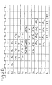
- the content P3 of the register 30 is added by the adder 27 to the result supplied by the multiplier circuit 23 and the result P4 obtained is loaded inside the register 31. All the operations which have just been described are carried out at the rate of a clock signal H as shown using the table in FIG. 2B.
- the complex multiplication will only last under these conditions the time to bring the two real parts of 16 bits and the two imaginary parts of 16 bits to the input of the multiplier circuit, that is to say the time of two instructions if the microprocessor is provided with two memories.
- the real and complex multipliers which have just been described are produced using fixed structures which do not allow easy adaptation to situations where for example complex numbers can have variable lengths as is the case of some applications where operands can have lengths of 8 bits.
- a 16-bit word can alone carry a complex number with real or imaginary 8-bit parts, and in these situations a single instruction cycle is necessary to bring it to an input of the multiplier.
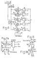
- the device according to the invention which is shown in FIG. 4 allows these various operations to be carried out while requiring only a few modifications to the structure of the complex multipliers 16 x 16 previously described. This device makes it possible in particular to carry out at a frequency twice as high a multiplication of two complex numbers 8 bits plus 8 bits.
- the device according to the invention which is represented in FIG. 4 comprises a first register 35 on the input of which the multiplier number X of N bits is applied, a second register 36 on the input of which the multiplicand number Y of N is applied bits, a first operator 37 and a second operator 38 each having three inputs E1, E2 and S and one output R.
- Each of the operators 37 and 38 performs the product of the numbers applied to their inputs E1 and E2 and adds the result obtained to the number which is applied to their input S.
- the least significant bits of register 35, by X, the most significant bits of register 35 and respectively by Y, and Y2 the least significant and most significant bits of register 36, bits X, and Y, are applied respectively to the inputs E1 and E2 of the first operator 37 and the bits X 2 and Y 2 are applied respectively to the inputs E1 and E2 of the second operator 38.
- the values given to X1 and X2 are different.
- the interest of the structure which is represented in figure 4 resides in the fact that while keeping a compatible structure of a multiplier dealing with real numbers, it is possible to carry out complex multiplications twice as quickly as if one had a standard multiplier.
- the result is obtained at an offset close to 2 .
- the operation is carried out in two stages.
- the calculation of the real part is carried out during the first stage and the calculation of the imaginary part is carried out during the second stage.
- the calculation of the real part carried out in the first step gives and and the calculation of the imaginary part carried out in the second step gives
- the multiplication operation is therefore carried out in two cycles whereas with a standard multiplier it would take four cycles - (since there are four multiplications X 'Y', X 'Y ", X" Y', X "Y "without counting the additional additions to be made).
- the architecture of the multiplier according to the invention which has just been described is independent of the method used to carry out the multiplication (BOOTH algorithm for example which decomposes the multiplier into sub-multipliers processing two bits of the number Y) it is also independent the number of internal registers buffer stages if it is desired, for example, to make a multiplier using the "pipeline" technique.
- This multiplier also has the other advantage that the additional additions for calculating the real and imaginary parts do not require additional circuits because they are automatically produced by the sub-multipliers.
- This multiplier circuit comprises a register 39 for memorizing the multiplicand X which is coupled to first operand inputs of K sub multipliers denoted respectively by 40 to 40 + K, the second operand inputs of these multipliers being connected to means of treatment noted respectively from 50 to 50 + K of the multiplier number Y.
- the multiplier acts by successive additions of partial products starting with that which concerns the bit YO of the multiplier number Y.
- the structure is made so that at the output of any sub-multiplier L we obtain a by-product SP L formed by a number of (16 + n L + 1) signed bits, a carry vector RL attached to the results SPL and an indicator r L such that if one propagated the carryings of the vector r L in the result SPL one would obtain a shift close, but with an exact sign, the number
- stage 50 + K which processes the bit Y15, the indicator r is zero and the propagation of the vector of retentions R in the byproduct SP gives a number exactly equal to the signed product XY.
- the multiplier of FIG. 5 is arranged according to the embodiment of FIG. 6 to allow it to perform products of complex numbers coded on 16 bits.
- the multiplicand X is stored in FIG. 6 inside a register 61 but, unlike in FIG. 5, the register 61 is connected by means of registers 62 and 63 respectively on the one hand , to the first operand inputs of multiplier circuits 64 to 71 and on the other hand, to the first operand inputs of sub-multiplier circuits 72 to-79.
- Each SPL by-product obtained from a sub-multiplier circuit is propagated in the next sub-multiplier and the final by-product obtained from the sub-multiplier 79 is recorded in an adder 80.
- the processing means 81 , 82 to 96 execute treatments on the multiplier number Y and apply, via the processing means 81, 82 and 96, the result of this processing on the second operand inputs of the sub-multipliers 64 to 79.
- the number X is formed by a number of 16 bits - (X15 to XO).
- the number X ' is of the form and the number X "is of the form the number Y which represents the multiplier number is coded in the same way.
- the circuits of FIG. 6 break down the multiplication operation into two consecutive phases, consisting on the one hand, in calculating the real part of the product X 'Y' -X "Y" and on the other hand, to calculate the imaginary part of the product, ie X 'Y "+ X" Y.
- the real part of the product is calculated by presenting the signed value 2 B X 'in the register 62 and the value -X "in the register 63.
- the sub-multiplier 71 processing the bit Y7 provides a by-product SP 'and a retaining vector R', which if assembled would be equal to the product 2 B X 'Y'.
- SP 'and R' are presented at the input of the sub-multiplier 72 processing leibit Y8.
- 79 provides a by-product SP "and a vector of retentions R" which assembled by the adder 80 are equal to 2 8 X 'Y' -2 8 X "Y".
- the imaginary part of the product is calculated.
- the operation proceeds in the same way as previously by presenting the binary number 2 "X" instead of the binary number 2 'X' in the register 62 and the binary number X 'instead of -X "at the input of the sub-multiplier 72 processing the bit Y8
- the sub-multiplier 71 and the processing means 88 which are organized so that the carry indicator r at the output of the processing means 88 always has a zero value, that is to say that the byproduct SP and the vector of deductions R obtained at the output of the sub-multipliers 71 form the exact product of the number of 8 bits signed from Y7 to YO by the number of 16 signed bits presented at the input of the sub-multiplier processing the bit Y0.
- the sub-multipliers used for implementing the multiplier according to the invention are of a particular type and an exemplary embodiment of these sub-multipliers is shown in FIG. 7A.
- the sub-multiplier shown in FIG. 7A comprises an adder with three inputs 97, a switcher 98 and a decoder 99.
- the switcher 98 is controlled from the decoder 99, the decoding table of which is shown in FIG. 7B.
- the decoder 99 has three inputs to which are respectively applied a carry bit C. (t-1) coming, in the assembly of the sub-multipliers to form the full multiplier, from the previous sub-multiplier, and the bits Y n and Y n + 1 of rows n and n + 1 of the multiplier number Y.
- the decoder 99 also has three outputs denoted B, Q and C ,.
- the output B takes the state 0 when the sum of the binary numbers 2Y n + 1 + Y n + C ,. 1 is equal to 0, 1, 2 or 4 and takes the binary value of 1 when this sum of binary numbers is equal to three.
- the output Q of the decoder controls the switcher 98 which provides on its output the numbers 0, X, 2X or X as a function of the values of 2Y n + 1 + Y n + C t-1 .
- the number 0 is obtained when the sum 2Y n + 1 + Y n + C t-1 is equal to O or 4.
- the output A restores the value of the multiplicand X which is applied to the input of the switch 98, when the sum 2Y n + 1 + Y n + C t-1 is equal to 1 or the product 2X when 2Y n + Y n + C t-1 is equal to 2 or the value of X complemented X when the sum 2Y n +1 + Y n + C,., Is equal to 3.
- the adder 97 performs the addition of the binary word obtained at the output A of the switcher with the two outputs S (t-1) and R (t- 1) of the previous sub-multiplier taking into account the state of bit B (t-1 ) coming from the previous sub-multiplier.
- the result of this addition appears in the form of a sum S (t) at the output S1 of the adder and in the form of a transfer R (t) on the output S2 of the adder 97.
- the multiplier according to the invention is carried out using seven sub-multipliers of the type of that which has just been described with the aid of FIGS. 7A and 7B.
- the sub-multiplier which has just been described is represented in a simplified symbolic form in FIG. 8. In the simplified form which is represented in FIG. 8 the sub-multiplier has 5 inputs.
- a first entry receives the adjacent dibits Y n + 1 and Y n of order n and n + 1 of the word Y, a second entry receives the result obtained from the previous sub-multiplier S (t-1) a third entry receives the report R (t-1) a fourth input receives the carry bit C (t-1) and finally a fifth input receives the correction bit B (t-1) from the previous sub-multiplier. It provides a result S and a report R on two outputs.
- the production of the multiplier requires, in addition to the sub-multipliers which have just been described, the use of another subset of a somewhat particular nature since it processes a sign bit, this last subset is designated by the graphic symbol which is represented in FIG. 9A and presents the truth table of FIG. 9B. In its structure it is equivalent to that which has been described with the aid of FIG.
- FIG. 14 A symbolic representation of this sub-multiplier is shown in FIG. 9C.
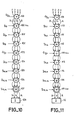
- FIG. 10 illustrates an embodiment of a multiplier of real numbers, it is made up of 9 sub-multipliers noted respectively from 100, 100bis to 108 and a fast summator 108bis giving the final result from the last partial sum and associated deductions.
- FIG. 11 illustrates an embodiment of an eight-bit complex number multiplier, this multiplier being composed of 7 sub-multipliers 109 to 115 of the type shown in FIG. 8, of a sub-multiplier 115bis of the type of that shown in FIG. 9A and of the particular sub-multiplier 115ter of the type shown in FIG. 9C.
- the multiplier also includes a fast adder circuit 116.
- the multiplier represented in FIG. 11 comprises an upper part to process the bits of the multiplier from Y1 to Y7 and a lower part which processes the bits of the multiplier from Y8 to Y15.
- the upper part includes sub-multipliers 112 and 115bis and a logic 200 which groups the functionalities of the sub-multipliers 109, 110 and 111 and the lower part includes the sub-multipliers 113, 114, 115 and 115ter.
- bits of the multiplier YO to Y4 are applied to the logic 200, the bits Y5 Y6 are applied to the sub-multiplier 112, the bit Y7 is applied to the sub-multiplier 115bis at the same time as the bit C8 indicating the type of multiplication , complex or real.
- bits Y8 and Y9 are applied to the multiplier 113, bits Y10 and Y11 are applied to the sub-multiplier 114, bits Y12 and Y 1 3 are applied to the sub-multiplier 115 and bits Y14 and Y15 are applied to the 115ter sub-multiplier.
- bits Y8 and Y9 are applied to the multiplier 113
- bits Y10 and Y11 are applied to the sub-multiplier 114
- bits Y12 and Y 1 3 are applied to the sub-multiplier 115
- bits Y14 and Y15 are applied to the 115ter sub-multiplier.
- the decoders 99 of the logic 200 of the sub-multipliers 113 to 115 have a decoding table which is in accordance with that of FIG. 7B
- the decoder 99 of the sub-multiplier 115bis has a table decoding which conforms to that shown in FIG. 13 which is a more advanced version of the table of FIG. 9A
- the decoder 99 of the sub-multiplier 115ter has a decoding table conforming to that of FIG. 14.
- the multiplier of FIG. 12 allows operations to be carried out on real numbers and on complex numbers. It is provided with an upper input formed by logic 200 and with a lower input which is constituted by the sub-multiplier 113.
- the switching between the upper and lower inputs is carried out using a circuit formed by elements 118 to 129.
- This switcher receives control signals designated by C8, P ", T o and T,.
- C8 indicates the eight-bit complex mode.
- P indicates that it is a question of carrying out the conjugate product X x Y '.
- T orders the first phase of calculation corresponding to the calculation of the real part of the product between the two numbers X and Y and T, orders the second phase of calculation of the imaginary part of the product between the two names bres X and Y.
- the switcher includes a register 118 for loading the multiplicand X whose real parts RE and imaginary IM respectively occupy the first eight bits and the following eight bits of register 118.
- the first eight bits representing the real part RE of number X are applied through the switch 128bis in real mode directly to the input of logic 200 or are applied to the lower input of the multiplier through an inverter 119, switches 120, 121 and a summator 125.
- the switch 120 is open when the condition C8 x T, x P * is fulfilled and the switch 121 is open when the condition C8 + C8 x T, x P * is carried out.
- the last 8 bits of register 118 are applied to logic 200 through switch 129 when the condition C8 x T, + vs 8 is performed, they are transmitted to the lower part through, either from the inverter 122 and from the switch 123 when the condition C8 ⁇ T o x ⁇ * is performed, either through the switch 124 when the condition C8 x T o x P * is achieved and through the summator 125.
- the most significant bits of the register 118 can also be transmitted directly to the input of the multiplier 111 through switch 127 and at the input of logic 200 through switch 129 when the condition c8 is carried out.
- the switch 126 duplicates the most significant bit of the summator 125 8 times and applies it to the input of the sub-multiplier 113 in the complex operating mode.
- the calculation of the real parts of XY or of XY * is carried out during a first cycle controlled by the signal T o and the calculation of the imaginary parts during a second calculation cycle controlled by the signal T1.
- the lower part receives the imaginary part - X IM and the sign indication of -X 1M when calculating the real part of the product XY and which takes place during the first calculation cycle. And it receives during the second cycle of calculation of the imaginary part the real part X RE of the number X with its indication of sign during the calculation of the product X Y.
- the lower part receives during the first cycle of calculation the imaginary number X IM and the indication of sign X of X IM and it receives during the second cycle of calculation of the imaginary part of the product XY * the number -X RE and the sign indication of the number -X RE .
- This referral is made by switches 120 to 124 on the one hand, and 127 and 126 on the other.
Abstract
Description
La présente invention a pour objet un multiplieur pour la multipiication de deux nombres complexes. Elle s'applique plus particulièrement à la réalisation de multiplieurs de nombres complexes dont les parties réelle et imaginaire sont exprimées sur des longueurs de 8 bits.The present invention relates to a multiplier for the multipication of two complex numbers. It applies more particularly to the production of multipliers of complex numbers whose real and imaginary parts are expressed over lengths of 8 bits.
Dans certains domaines du traitement numérique du signal, en particulier pour traiter la phase d'un signal, les opérations de calcul sont effectuées sur des nombres complexes. En employant une architecture numérique standard prévue pour le traitement de nombres réels, la multiplication de nombres complexes demande quatre multiplications et deux additions ou soustractions de nombres réels auxquelles s'ajoutent quelques instructions d'aiguillage.In certain fields of digital signal processing, in particular for processing the phase of a signal, the calculation operations are carried out on complex numbers. By using a standard digital architecture intended for the processing of real numbers, the multiplication of complex numbers requires four multiplications and two additions or subtractions of real numbers to which are added some routing instructions.
Certaines architectures apportent une amélioration sur ce point en automatisant le séquencement des multiplications et des additions de manière à ramener le coût en temps de la multiplication complexe à celui de quatre multiplications réelles.Certain architectures bring an improvement on this point by automating the sequencing of multiplications and additions so as to reduce the time cost of complex multiplication to that of four real multiplications.
Le but de l'invention est de permettre la modification d'un type particulier de multiplieur de nombres réels signés exprimés sur 16 bits pour le rendre apte à exécuter en un temps égal à celui qui est nécessaire pour deux multiplications réelles une multiplication de deux nombres complexes dont les parties réelles et imaginaires sont exprimées sur 8 bits.The object of the invention is to allow the modification of a particular type of multiplier of signed real numbers expressed on 16 bits to make it capable of executing in a time equal to that which is necessary for two real multiplications a multiplication of two numbers complexes whose real and imaginary parts are expressed on 8 bits.
A cet effet, l'invention a pour objet un multiplieur pour la multiplication de deux nombres complexes X = X' + JX" et Y = Y' + JY" de N bits - (N nombre pair), du type comprenant une première suite et une deuxième suite de K sous-multiplieurs reliés en cascade, le résultat fourni par les sous-multiplieurs de la première suite étant appliqué aux sous-multiplieurs de la deuxième suite, chaque suite comprenant des première et deuxième entrées d'opérande, une troisième entrée S et une sortie R et étant agencée de manière à fournir sur sa sortie R le produit des nombres binaires appliqués sur ses première et deuxième entrée d'opérande augmenté d'une quantité binaire égale au nombre binaire appliqué sur sa troisième entrée S, caractérisé en ce que les nombres complexes X et Y de N bits sont partagés respectivement en nombres X1, X2 et Y1, Y2 de ![]()
![]()
L'invention a principalement pour avantage qu'elle permet de faire travailler une machine de traitement du signal qui fonctionne habituellement sur des mots complexes de N bits, sur un mode nouveau doublànt la capacité des calculs avec des mots complexes de ![]()
![]()
D'autres caractéristiques et avantages de l'invention apparaîtront au cours de la description qui suit faite aux regards des dessins annexés dans lesquels :
- -la figure 1 représente un multiplieur de l'art connu capable d'effectuer des opérations sur des nombres réels de N bits,
- -la figure 2A représente un multiplieur de l'art connu de deux nombres complexes de N bits,
- -la figure 2B illustre le fonctionnement du multiplieur de la figure 2A
- -la figure 3 montre un circuit qu'il faut adjoindre au multiplieur de l'art connu de la figure 2A pour obtenir le résultat complet de la multiplication de deux nombres complexes,
- -la figure 4 est un schéma synoptique du multiplieur selon l'invention,
- -la figure 5 est un schéma de principe illustrant un mode de fonctionnement d'un multiplieur de nombres réels à 16 bits,
- -la figure 6 est un schéma de principe montrant la modification qu'il faut apporter aux multiplieurs de la figure 5 pour obtenir un multiplieur de nombres complexes codé sur 16 bits,
- -la figure 7A est une représentation d'un sous-multiplieur pour la réalisation du
multiplieur 16 bits selon l'invention, - -la figure 7B représente la table de décodage d'un décodeur de sous-multiplieur du type représenté à la figure 7A.
- -la figure 8 est une représentation symbolique du multiplieur de la figure 7A,
- -les figures 9A et 9C illustrent deux représentations symboliques de deux sous-multiplieurs différents de la figure 8,
- -la figure 9B représente la table de décodage du décodeur constituant le sous-multiplieur de la figure 9A,
- -la figure 9D représente la table de décodage du décodeur constituant le sous-multiplieur de la figure 9C
- -la figure 10 illustre l'organisation d'un multiplieur 16 bits à l'aide de la représentation symbolique de la figure 9,
- -la figure 11 est une représentation de l'organisation d'un multiplieur selon l'invention à l'aide de la représentation symbolique de la figure 9,
- -la figure 12 est un mode de représentation détaillé du multiplieur selon l'invention,
- -les figures 13 et 14 des tables de décodage.
- FIG. 1 represents a multiplier of the known art capable of carrying out operations on real numbers of N bits,
- FIG. 2A represents a known art multiplier of two complex numbers of N bits,
- FIG. 2B illustrates the operation of the multiplier of FIG. 2A
- FIG. 3 shows a circuit which must be added to the multiplier of the known art of FIG. 2A to obtain the complete result of the multiplication of two complex numbers,
- FIG. 4 is a block diagram of the multiplier according to the invention,
- FIG. 5 is a block diagram illustrating an operating mode of a 16-bit real number multiplier,
- FIG. 6 is a block diagram showing the modification that must be made to the multipliers of FIG. 5 in order to obtain a multiplier of complex numbers coded on 16 bits,
- FIG. 7A is a representation of a sub-multiplier for producing the 16-bit multiplier according to the invention,
- FIG. 7B represents the decoding table of a sub-multiplier decoder of the type shown in FIG. 7A.
- FIG. 8 is a symbolic representation of the multiplier of FIG. 7A,
- FIGS. 9A and 9C illustrate two symbolic representations of two different sub-multipliers of FIG. 8,
- FIG. 9B represents the decoding table of the decoder constituting the sub-multiplier of FIG. 9A,
- FIG. 9D represents the decoding table of the decoder constituting the sub-multiplier of FIG. 9C
- FIG. 10 illustrates the organization of a 16-bit multiplier using the symbolic representation of FIG. 9,
- FIG. 11 is a representation of the organization of a multiplier according to the invention using the symbolic representation of FIG. 9,
- FIG. 12 is a detailed representation of the multiplier according to the invention,
- FIGS. 13 and 14 of the decoding tables.
La méthode directe communément employée pour multiplier deux nombres réels codés sur N bits consiste à additionner le multiplicande décalé de K rangs vers la gauche lorsque le bit de numéro K du multiplieur est égal à 1. Cette méthode, lorsqu'elle est réalisée en logique câblée donne lieu à un grand nombre de portes logiques qui croit comme N2 le carré du nombre de bits de chaque nombre binaire à multiplier et présente un temps d'exécution qui correspondant à environ N additions de N bits. Pour pallier cet inconvénient les concepteurs utilisent souvent une autre méthode qui consiste à décomposer la multiplication de N bits par N bits, en n multiplication de N bits par ![]()
![]()
![]()
![]()
![]()
![]()
![]()
![]()
![]()
![]()
![]()
![]()
Le résultat de la multiplication effectuée par le multiplieur 5 est rangé dans un registre 9 au rythme d'une l'horloge H, puis le contenu du registre 9 est additionné par un additionneur 10 au résultat M6 fourni par le multiplieur 6. Le résultat de l'addition M5 + M6 est mémorisé dans un registre 11. La sortie du registre 11 est également appliquée au rythme de l'horloge H sur une première entrée d'opérande d'un additionneur 12 dont la deuxième entrée d'opérande reçoit la sortie du multiplieur 7 et le résultat Ms + M6 + M, de l'addition effectué sur ses deux opérandes est mémorisé à l'intérieur d'un registre 13. Le contenu du registre 13 est à son tour appliqué à une première entrée d'opérande d'un additionneur 14 dont la deuxième entrée d'opérande est reliée à la sortie du multiplieur 8 et le résultat M5 + M6 + M, + M, de l'addition effectué par l'additionneur 14 sur les deux opérandes est rangé à l'intérieur d'un registre 15 au rythme de l'horloge H. L'horloge H est ajustée en fonction du temps nécessaire à une multiplication 16 x 4 qui est à peu près le quart du temps nécessaire à une multiplication 16 x 16. La méthode qui vient d'être exposée permet par conséquent d'amener deux nouveaux opérandes à chaque top de l'horloge et le nombre de multiplications par seconde dont ce multiplieur est capable est dans ces conditions quatre fois plus élevé que celui que l'on peut obtenir par la méthode directe.The result of the multiplication carried out by the
Le principe de la multiplication qui vient d'être exposé reste valable moyennant certains précautions concernant les bits de signe des deux opérandes, lorsque les nombres sont codés en complément à 2 avec un bit de signe au MSB.The principle of multiplication which has just been explained remains valid subject to certain precautions concerning the sign bits of the two operands, when the numbers are coded in addition to 2 with a sign bit at the MSB.
Comme la vitesse de calcul du multiplieur est liée à l'horloge H qui elle-même est liée au temps nécessaire à la multiplication d'un nombre N bits par un nombre de ![]()
![]()
![]()
![]()
![]()
![]()
![]()
![]()
![]()
![]()
On pourra se reporter utilement pour la description de ces algorithmes à l'article de Mac Sor- ley publié dans la revue PROC. OF IRE, de janvier 1961.We can usefully refer to the description of these algorithms in the article by Mac Silly published in the review PROC. OF IRE, from January 1961.
Dans la pratique, il est souvent plus aisé de mettre en oeuvre des tranches de multiplieurs de N bits par L bits avec L petit, car l'algorithme de BOOTH devient de plus en plus compliqué à mettre en oeuvre lorsque L devient supérieur à quatre. Avec les technologies NMOS actuelles, le temps de transit à travers une tranche de multiplieurs de 16 4 est inférieur à 100 ns et la limitation de la vitesse du multiplieur total de 16 × 16 vient de la difficulté d'amener les opérandes X et Y aux bornes du multiplieur à chaque top de l'horloge H. Ainsi, lorsque le multiplieur est intégré dans un microprocesseur de traitement du signal, le temps de cycle d'une instruction est souvent un multiple du temps de cycle de l'horloge H c'est-à-dire de deux ou quatre.In practice, it is often easier to implement slices of multipliers of N bits by L bits with L small, because the BOOTH algorithm becomes increasingly complicated to implement when L becomes greater than four. With current NMOS technologies, the transit time through a slice of multipliers of 16 4 is less than 100 ns and the limitation of the speed of the total multiplier of 16 × 16 comes from the difficulty of bringing the operands X and Y to bor nes of the multiplier at each top of the clock H. Thus, when the multiplier is integrated into a signal processing microprocessor, the cycle time of an instruction is often a multiple of the cycle time of the clock H c ' that is to say two or four.
La multiplication de deux nombres complexes X + jX' et Y + jY' formés chacun d'une partie réelle (X, Y) et d'une partie imaginaire (X', Y') codées chacune sur N bits est classiquement réalisée à l'aide d'un dispositif du type de celui qui est représenté à la figure 2A (où N = 16). Ce dispositif comporte typiquement quatre registres 16, 17, 18 et 19, quatre circuits multiplieurs référencés de 20 à 23, quatre circuits additionneurs référencés de 24 à 27 et quatre registres référencés de 28 à 31. Les premières entrées d'opérande des multiplieurs 20 à 23 sont reliées respectivement aux sorties des registres 16 à 19. Ces multiplieurs reçoivent respectivement sur leur deuxième entrée d'opérande des mots binaires E2,, E=, E23 et E24 qui représentent les quatre mots de quatre bits du nombre multiplieur. La sortie du multiplieur 20 est appliquée à une première entrée d'opérande d'un additionneur 24 dont la deuxième entrée d'opérande reçoit un nombre binaire nul, le résultat P1 de l'addition est chargé à l'intérieur du registre 28. Le contenu P1 du registre 28 est ajouté dans l'additionneur 25 au résultat fourni par la sortie du multiplieur 21 et le résultat P2 est chargé à l'intérieur du registre 29. De même le contenu P2 du registre 29 est additionné par l'additionneur 26 au résultat fourni par le circuit multiplieur 22 et le résultat P3 est chargé à l'intérieur du registre 30. Enfin le contenu P3 du registre 30 est additionné par l'additionneur 27 au résultat fourni par le circuit multiplieur 23 et le résultat P4 obtenu est chargé à l'intérieur du registre 31. L'ensemble des opérations qui viennent d'être décrites est effectué au rythme d'un signal d'horloge H de la façon représentée à l'aide du tableau de la figure 2B.The multiplication of two complex numbers X + jX 'and Y + jY' each formed of a real part (X, Y) and an imaginary part (X ', Y') each coded on N bits is conventionally performed at l using a device of the type shown in FIG. 2A (where N = 16). This device typically comprises four
Ce tableau fait apparaître les quatre produits partiels XY, X'Y', X'Y et XY' du produit complexe - (Y + jY')(X + jX'). Ces produits apparaissent dans le registre 31 avec un retard de quatre périodes d'horloge H. Pour obtenir le résultat de la multiplication complexe il est par conséquent nécessaire d'adjoindre à la sortie du registre 31 deux registres accumulateurs 33 et 34 tous deux reliés à la sortie d'un opérateur 32 de la manière représentée à la figure 3. Si IM et RE désignent les contenus des registres 33 et 34, l'opérateur 32 assure les opérations S = P4, S = IM + P4 ou S = RE -P4. Cet opérateur permet d'effectuer la multiplication complexe en quatre périodes d'horloge H. En considérant par exemple le cas où les opérations précédentes sont effectuées à l'aide d'un microprocesseur dont l'horloge instruction est égale à ![]()
![]()
Les multiplieurs réels et complexes qui viennent d'être décrits sont réalisés à l'aide de structures figées qui ne permettent pas de s'adapter aisément à des situations où par exemple les nombres complexes peuvent avoir des longueurs variables comme c'est le cas de certaines applications où les opérandes peuvent avoir des longueurs de 8 bits. Dans certaines applications un mot de 16 bits peut véhiculer à lui tout seul un nombre complexe à parties réelle ou imaginaire à 8 bits et dans ces situations un seul cycle d'instruction est nécessaire pour l'amener à une entrée du multiplieur. Le dispositif selon l'invention qui est représenté à la figure 4 permet d'effectuer ces diverses opérations en ne demandant que peu de modifications à la structure des multiplieurs complexes 16 x 16 précédemment décrite. Ce dispositif permet en particulier d'effectuer à une fréquence deux fois plus élevée une multiplication de deux nombres complexes 8 bits plus 8 bits.The real and complex multipliers which have just been described are produced using fixed structures which do not allow easy adaptation to situations where for example complex numbers can have variable lengths as is the case of some applications where operands can have lengths of 8 bits. In certain applications, a 16-bit word can alone carry a complex number with real or imaginary 8-bit parts, and in these situations a single instruction cycle is necessary to bring it to an input of the multiplier. The device according to the invention which is shown in FIG. 4 allows these various operations to be carried out while requiring only a few modifications to the structure of the
Le dispositif selon l'invention qui est représenté à la figure 4 comprend un premier registre 35 sur l'entrée duquel est appliqué le nombre multiplieur X de N bits, un deuxième registre 36 sur l'entrée duquel est appliqué le nombre multiplicande Y de N bits, un premier opérateur 37 et un deuxième opérateur 38 ayant chacun trois entrées E1, E2 et S et une sortie R. Chacun des opérateurs 37 et 38 effectue le produit des nombres appliqués sur leurs entrées E1 et E2 et additionne le résultat obtenu au nombre qui est appliqué sur leur entrée S. En désignant par X, les ![]()
![]()
![]()
![]()
Le multiplieur qui vient d'être décrit permet d'effectuer des opérations de multiplication sur des nombres X, Y réels ou complexes écrits dans un format comprenant N bits.
- Dans le format réel X vérifie la relation X =

- et dans le format complexe X vérifie la relation X = X' + JX" , X' représentant la partie réelle et JX" représentant la partie imaginaire.
- In the real format X checks the relation X =
- and in the complex format X checks the relation X = X '+ JX ", X' representing the real part and JX" representing the imaginary part.
Le multiplieur de la figure 4 effectue le produit P = X × Y des nombres X et Y appliqués respectivement sur les entrées des registres 35 et 36. Le nombre Y est partagé en deux nombres Y1 = Y' et Y2 = Y"x ![]()
![]()
En mode réel X1 = X2 = X = (X' + ![]()
- En mode complexe pour le calcul de la partie réelle X1 = X' 2

- et X2 = -X" et pour le calcul de la partie imaginaire X1 = X" x

- In complex mode for the calculation of the real part X 1 = X ' 2
- and X2 = -X "and for the calculation of the imaginary part X1 = X" x
L'intérêt de la structure qui est représentée à la figure 4 réside dans le fait que tout en gardant une structure compatible d'un multiplieur traitant des nombres réels, il est possible de réaliser des multiplications complexes deux fois plus rapidement que si l'on disposait d'un multiplieur standard. Le résultat est obtenu à un décalage près de 2 ![]()
![]()
![]()
![]()
![]()
![]()
![]()
![]()
![]()
![]()
L'opération de multiplication s'effectue par conséquent en deux cycles alors que avec un multiplieur standard il faudrait quatre cycles - (puisqu'il y a quatre multiplications X' Y', X' Y", X" Y', X" Y" sans compter les additions supplémentaires qui sont à réaliser).The multiplication operation is therefore carried out in two cycles whereas with a standard multiplier it would take four cycles - (since there are four multiplications X 'Y', X 'Y ", X" Y', X "Y "without counting the additional additions to be made).
En mode réel le multiplieur de la figure 4 donne les résultats suivants :![]()

![]()
L'architecture du multiplieur selon l'invention qui vient d'être décrite est indépendante de la méthode retenue pour exécuter la multiplication (algorithme de BOOTH par exemple qui décompose le multiplieur en sous-multiplieurs traitant deux bits du nombre Y) elle est aussi indépendante du nombre de registres internes étages tampons si l'on désire par exemple réaliser un multiplieur utilisant la technique "pipe-line".The architecture of the multiplier according to the invention which has just been described is independent of the method used to carry out the multiplication (BOOTH algorithm for example which decomposes the multiplier into sub-multipliers processing two bits of the number Y) it is also independent the number of internal registers buffer stages if it is desired, for example, to make a multiplier using the "pipeline" technique.
Ce multiplieur présente aussi comme autre intérêt que les additions complémentaires pour calculer les parties réelles et imaginaires ne nécessitent pas de circuits supplémentaires car elles sont automatiquement réalisées par les sous-multiplieurs.This multiplier also has the other advantage that the additional additions for calculating the real and imaginary parts do not require additional circuits because they are automatically produced by the sub-multipliers.
Une application du principe de l'invention à la réalisation d'un circuit multiplieur sur des nombres réels est représentée à la figure 5 dans le cas ou les nombres sont représentés sur 16 bits. Ce circuit multiplieur comprend un registre 39 de mémorisation du multiplicande X qui est couplé à des premières entrées d'opérande de K sous multiplieurs notés respectivement de 40 à 40 + K, les deuxièmes entrées d'opérande de ces multiplieurs étant reliées à des moyens de traitement notés respectivement de 50 à 50 + K du nombre multiplieur Y.An application of the principle of the invention to the production of a multiplier circuit on real numbers is represented in FIG. 5 in the case where the numbers are represented on 16 bits. This multiplier circuit comprises a
Le multiplieur agit par additions successives de produits partiels en commençant par celui qui concerne le bit YO du nombre multiplieur Y. La structure est faite de façon qu'à la sortie d'un sous-multiplieur L quelconque on obtienne un sous produit SPL formé par un nombre de (16 + nL + 1) bits signés, un vecteur de retenue RL attaché aux résultats SPL et un indicateur rL tels que si l'on propageait les retenues du vecteur rL dans le résultat SPL on obtiendrait à un décalage près, mais avec un signe exact, le nombre
En sortie de l'étage 50 + K qui traite le bit Y15 l'indicateur r est nul et la propagation du vecteur de retenues R dans le sous produit SP donne un nombre exactement égal au produit signé XY.At the output of
Le multiplieur de la figure 5 est aménagé selon le mode de réalisation de la figure 6 pour lui permettre d'effectuer des produits de nombres complexes codés sur 16 bits. Comme sur la figure 5 le multiplicande X est mémorisé sur la figure 6 à l'intérieur d'un registre 61 mais à la différence de la figure 5 le registre 61 est relié par l'intermédiaire de registres 62 et 63 respectivement d'une part, aux premières entrées d'opérande de circuits multiplieurs 64 à 71 et d'autre part, aux premières entrées d'opérande de circuits sous-multiplieurs 72 à-79. Chaque sous-produit SPL obtenu d'un circuit sous-multiplieur est propagé dans le sous-multiplieur suivant et le sous-produit final obtenu du sous-multiplieur 79 est enregistré dans un additionneur 80. Comme sur la figure 5 des moyens de traitement 81, 82 à 96 exécutent des traitements sur le nombre multiplieur Y et appliquent par l'intermédiaire des moyens de traitement 81, 82 et 96 le résuffat de ce- traitement sur les deuxièmes entrées d'opérande des sous-multiplieurs 64 à 79.The multiplier of FIG. 5 is arranged according to the embodiment of FIG. 6 to allow it to perform products of complex numbers coded on 16 bits. As in FIG. 5, the multiplicand X is stored in FIG. 6 inside a
Le- membre multiplicnade X est formé d'une partie réelle X' et d'une partie imaginaire X" qui représentent le nombre complexe X = X' + JX" Le nombre X est formé d'un nombre de 16 bits - (X15 à XO). Le nombre X' est de la forme![]()
![]()
et d'autre part, à calculer la partie imaginaire du produit soit X' Y" + X" Y.The multiplicnad member X is formed by a real part X 'and by an imaginary part X "which represent the complex number X = X' + JX" The number X is formed by a number of 16 bits - (X15 to XO). The number X 'is of the form ![]()
![]()
and on the other hand, to calculate the imaginary part of the product, ie X 'Y "+ X" Y.
Durant la première phase la partie réelle du produit est calculée en présentant la valeur signée 2B X' dans le registre 62 et la valeur -X" dans le registre 63. Le sous-multiplieur 71 traitant le bit Y7 fournit un sous-produit SP' et un vecteur de retenue R', qui s'ils étaient assemblés seraient égaux au produit 2B X' Y'. SP' et R' sont présentés à l'entrée du sous-multiplieur 72 traitant leibit Y8. Le sous-multiplieur 79 fournit un sous-produit SP" et un vecteur de retenues R" qui assemblés par l'additionneur 80 sont égaux à 28 X' Y' -28 X" Y".During the first phase the real part of the product is calculated by presenting the signed value 2 B X 'in the
Durant la deuxième phase la partie imaginaire du produit est calculée. L'opération se déroule de la même façon que précédemment en présentant le nombre binaire 2" X" au lieu du nombre binaire 2' X' dans le registre 62 et le nombre binaire X' au lieu de -X" à l'entrée du sous-multiplieur 72 traitant le bit Y8. Ces résultats sont obtenus moyennant une réalisation particulière du sous-multiplieur 71 et du moyen de traitement 88 qui sont organisés de façon que l'indicateur de retenue r à la sortie du moyen de traitement 88 ait toujours une valeur nulle, c'est-à-dire que le sous produit SP et le vecteur de retenues R obtenus à la sortie du sous-multiplieurs 71 forment le produit exact du nombre de 8 bits signés de Y7 à YO par le nombre de 16 bits signés présentés à l'entrée du sous-multiplieur traitant le bit Y0.During the second phase the imaginary part of the product is calculated. The operation proceeds in the same way as previously by presenting the
Les sous-multiplieurs utilisés pour la mise en oeuvre du multiplieur selon l'invention sont d'un type particulier et un exemple de réalisation de ces sous-multiplieurs est représenté à la figure 7A. Le sous-multiplieur représenté à la figure 7A comprend un additionneur à trois entrées 97, un aiguilleur 98 et un décodeur 99. L'aiguilleur 98 est commandé à partir du décodeur 99 dont la table de décodage est représentée à la figure 7B. Le décodeur 99 possède trois entrées sur lesquelles sont appliquées respectivement un bit de report C. (t-1) provenant, dans l'assemblage des sous-multiplieurs pour former le multiplieur complet, du sous-multiplieur précédent, et les bits Yn et Yn+1de rangs n et n + 1 du nombre multiplieur Y. Le décodeur 99 possède également trois sorties notées B, Q et C,. La sortie B prend l'état 0 lorsque la somme des nombres binaires 2Yn+1 + Yn + C,. 1 est égale à 0, 1, 2 ou 4 et prend la valeur binaire de 1 lorsque cette somme de nombres binaires est égale à trois. La sortie Q du décodeur commande l'aiguilleur 98 qui fournit sur sa sortie les nombres 0, X, 2X ou
Enfin un dernier type de sous-multiplieur est utilisé pour traiter également un bit de signe et sa table de vérité est représentée à la figure 14. Une représentation symbolique de ce sous-multiplieur est montrée à la figure 9C.Finally, a last type of sub-multiplier is used to also process a sign bit and its truth table is represented in FIG. 14. A symbolic representation of this sub-multiplier is shown in FIG. 9C.
Les sous-ensembles qui viennent d'être décrits à l'aide dès figures 7A, 8, 9A et 9C permettent de réaliser des multiplieurs pour la multiplication de nombres réels ou complexes du type de ceux qui sont représentés aux figures 10 et 11 et dont la représentation utilise le symbolisme des figures 8, 9A et 9C.The subsets which have just been described with the aid of FIGS. 7A, 8, 9A and 9C make it possible to produce multipliers for the multiplication of real or complex numbers of the type of those which are represented in FIGS. 10 and 11 and of which the representation uses the symbolism of figures 8, 9A and 9C.
La figure 10 illustre un mode de réalisation d'un multiplieur de nombres réels, il est constitué de 9 sous-multiplieurs notés respectivement de 100, 100bis à 108 et d'un sommateur rapide 108bis donnant le résultat final à partir de la dernière somme partielle et de retenues associées.FIG. 10 illustrates an embodiment of a multiplier of real numbers, it is made up of 9 sub-multipliers noted respectively from 100, 100bis to 108 and a fast summator 108bis giving the final result from the last partial sum and associated deductions.
La figure 11 illustre un mode de réalisation d'un multiplieur de nombres complexes huit bits, ce multiplieur étant composé de 7 sous-multiplieurs 109 à 115 du type de celui représenté à la figure 8, d'un sous-multiplieur 115bis du type de celui qui est représenté à la figure 9A et du sous-multiplieur particulier 115ter du type représenté à la figure 9C. Le multiplieur comprend également un circuit additionneur rapide 116.FIG. 11 illustrates an embodiment of an eight-bit complex number multiplier, this multiplier being composed of 7
Ce dernier mode de réalisation est représenté plus en détails sur le schéma de la figure 12 où l'on retrouve à l'intérieur de rectangles en pointillés les sous-multiplieurs 112 à 115ter de la figure 11. Le multiplieur représenté à la figure 11 comprend une partie supérieure pour traiter les bits du multiplieur de Y1 à Y7 et une partie inférieure qui traite les bits du multiplieur de Y8 à Y15. La partie supérieure comprend des sous-multiplieurs 112 et 115bis et une logique 200 qui regroupe les fonctionnalités des sous-multiplieurs 109, 110 et 111 et la partie inférieure comprend les sous-multiplieurs 113, 114, 115 et 115ter. Les bits du multiplieur YO à Y4 sont appliqués sur la logique 200, les bits Y5 Y6 sont appliqués sur le sous-multiplieur 112, le bit Y7 est appliqué sur le sous-multiplieur 115bis en même temps que le bit C8 indiquant le type de multiplication, complexe ou réel. Dans la partie inférieure les bits Y8 et Y9 sont appliqués sur le multiplieur 113, les bits Y10 et Y11 sont appliqués sur le sous-multiplieur 114, les bits Y12 et Y13 sont appliqués sur le sous-multiplieur 115 et les bits Y14 et Y15 sont appliqués sur le sous-multiplieur 115ter. Dans l'exemple de réalisation de la figure 12 les décodeurs 99 de la logique 200 des sous-multiplieurs 113 à 115 ont une table de décodage qui est conforme à celle de la figure 7B, le décodeur 99 du sous-multiplieur 115bis a une table de décodage qui est conforme à celle représentée à la figure 13 qui est une version plus évoluée de la table de la figure 9A et le décodeur 99 du sous-multiplieur 115ter possède une table de décodage conforme à celle de la figure 14. Le multiplieur de la figure 12 permet d'effectuer indifféremment des opérations sur des nombres réels et sur des nombres complexes. Il est muni d'une entrée supérieure formée de la logique 200 et d'une entrée inférieure qui est constituée par le sous-multiplieur 113. L'aiguillage entre les entrées supérieures et inférieures est effectué à l'aide d'un circuit formé des éléments 118 à 129. Cet aiguilleur reçoit des signaux de commande désignés par C8, P", To et T,. C8 indique le mode complexe huit bits. P" indique qu'il s'agit d'effectuer le produit conjugué X x Y'. T, commande la première phase de calcul correspondant au calcul de la partie réelle du produit entre les deux nombres X et Y et T, commande la deuxième phase de calcul de la partie imaginaire du produit entre les deux nombres X et Y. L'aiguilleur comprend un registre 118 pour charger le multiplicande X dont les parties réelles RE et imaginaires IM occupent respectivement les huit premiers bits et les huit bits suivants du registre 118. Les huit premiers bits représentant la partie réelle RE du nombre X sont appliqués au travers de l'interrupteur 128bis en mode réel directement à l'entrée de la logique 200 ou sont appliqués sur l'entrée inférieure du multiplieur au travers d'un inverseur 119, d'interrupteurs 120, 121 et d'un sommateur 125. En mode complexe (C8 = 1) les 8 premiers bits appliqués à la logique 200 sont mis à zéro. L'interrupteur 120 est ouvert lorsque la condition C8 x T, x P* est réalisée et l'interrupteur 121 est ouvert lorsque la condition
L'interrupteur 126 duplique 8 fois le bit de poids fort du sommateur 125 et l'applique à l'entrée du sous-multiplieur 113 dans le mode de fonctionnement complexe.The
L'aiguilleur qui vient d'être décrit a pour avantage qu'il permet d'appliquer le même nombre multiplicande X sur les entrées supérieures et inférieures du multiplieur lorsqu'il s'agit d'une multiplication de nombres réels et qu'il permet lorsqu'il s'agit d'une multiplication de nombres complexes d'effectuer la multiplication de nombres complexes X Y suivant les relations![]()
![]()
La partie inférieure reçoit la partie imaginaire - X IM et l'indica tion de signe de -X1M lors du calcul de la partie réelle du produit X Y et qui a lieu durant le premier cycle de calcul. Et elle reçoit durant le deuxième cycle de calcul de la partie imaginaire la partie réelle XRE du nombre X avec son indication de signe lors du calcul du produit X Y.The lower part receives the imaginary part - X IM and the sign indication of -X 1M when calculating the real part of the product XY and which takes place during the first calculation cycle. And it receives during the second cycle of calculation of the imaginary part the real part X RE of the number X with its indication of sign during the calculation of the product X Y.
Pour le calcul X Y* du produit X par le nombre Y conjugué, la partie inférieure reçoit pendant le premier cycle de calcul le nombre imaginaire XIM et l'indication de signe X de XIM et elle reçoit lors du deuxième cycle de calcul de la partie imaginaire du produit X Y* le nombre -XRE et l'indication de signe du nombre -XRE. Cet aiguillage est effectué par les interrupteurs 120 à 124 d'une part, et 127 et 126 d'autre part.For the calculation XY * of the product X by the number Y conjugated, the lower part receives during the first cycle of calculation the imaginary number X IM and the indication of sign X of X IM and it receives during the second cycle of calculation of the imaginary part of the product XY * the number -X RE and the sign indication of the number -X RE . This referral is made by
L'exemple qui vient d'être donné d'une réalisation préférée de l'invention n'est pas limitatif, il va de soi que d'autres variantes de réalisation sont possible notamment pour multiplier des nombres complexes ayant des longueurs N quelconques de bits tout en restant dans le cadre fixé par l'invention. En particulier, plusieurs modes de réalisation pourront être envisagés lorsque le multiplieur selon l'invention devra être intégré dans un ensemble plus vaste, formé par exemple par un processeur de traitement de signal ou tout dispositif équivalent pour profiter des avantages de l'architecture déjà fourni par cet ensemble.The example which has just been given of a preferred embodiment of the invention is not limiting, it goes without saying that other variant embodiments are possible in particular for multiplying complex numbers having any length N of bits while remaining within the framework set by the invention. In particular, several embodiments could be envisaged when the multiplier according to the invention must be integrated into a larger assembly, formed for example by a signal processing processor or any equivalent device to take advantage of the advantages of the architecture already provided. by this set.
Claims (9)
Applications Claiming Priority (2)
| Application Number | Priority Date | Filing Date | Title |
|---|---|---|---|
| FR8510875A FR2585150B1 (en) | 1985-07-16 | 1985-07-16 | MULTIPLIER FOR THE MULTIPLICATION OF TWO COMPLEX NUMBERS |
| FR8510875 | 1985-07-16 |
Publications (2)
| Publication Number | Publication Date |
|---|---|
| EP0209446A1 true EP0209446A1 (en) | 1987-01-21 |
| EP0209446B1 EP0209446B1 (en) | 1991-03-13 |
Family
ID=9321344
Family Applications (1)
| Application Number | Title | Priority Date | Filing Date |
|---|---|---|---|
| EP19860401493 Expired - Lifetime EP0209446B1 (en) | 1985-07-16 | 1986-07-04 | Multiplier for the multiplication of two complex numbers |
Country Status (4)
| Country | Link |
|---|---|
| EP (1) | EP0209446B1 (en) |
| JP (1) | JPS6222178A (en) |
| DE (1) | DE3678055D1 (en) |
| FR (1) | FR2585150B1 (en) |
Cited By (5)
| Publication number | Priority date | Publication date | Assignee | Title |
|---|---|---|---|---|
| EP0561411A2 (en) * | 1992-03-19 | 1993-09-22 | Nec Corporation | Adding multiplier |
| EP0629943A2 (en) * | 1993-05-21 | 1994-12-21 | Deutsche ITT Industries GmbH | Multiplier for real and complex numbers |
| EP0650115A1 (en) * | 1993-10-21 | 1995-04-26 | Kabushiki Kaisha Toshiba | Multiplier capable of calculating double precision, single precision, inner product and multiplying complex numbers |
| EP1162548A2 (en) * | 2000-06-05 | 2001-12-12 | DSP Group Ltd. | Complex multiplication dsp subarchitectures |
| US7555511B2 (en) | 2004-07-02 | 2009-06-30 | Ceva D.S.P. Ltd. | Methods for addressing input data values of a Fast Fourier Transform (FFT) calculation |
-
1985
- 1985-07-16 FR FR8510875A patent/FR2585150B1/en not_active Expired
-
1986
- 1986-07-04 EP EP19860401493 patent/EP0209446B1/en not_active Expired - Lifetime
- 1986-07-04 DE DE8686401493T patent/DE3678055D1/en not_active Expired - Fee Related
- 1986-07-16 JP JP61167726A patent/JPS6222178A/en active Pending
Non-Patent Citations (2)
| Title |
|---|
| ELECTRONIC ENGINEERING, vol. 42, no. 506, avril 1970, pages 71-73, Londres, GB; D.P. BURTON et al.: "A multiplier for complex binary numbers" * |
| PROCEEDINGS OF THE IEE, vol. 127, no. 2, avril 1980, pages 91-106, Stevenage, GB; S.S. MAGAR et al.: "Microprogrammable arithmetic element and its applications to digital signal processing" * |
Cited By (9)
| Publication number | Priority date | Publication date | Assignee | Title |
|---|---|---|---|---|
| EP0561411A2 (en) * | 1992-03-19 | 1993-09-22 | Nec Corporation | Adding multiplier |
| EP0561411A3 (en) * | 1992-03-19 | 1993-10-06 | Nec Corporation | Adding multiplier |
| EP0629943A2 (en) * | 1993-05-21 | 1994-12-21 | Deutsche ITT Industries GmbH | Multiplier for real and complex numbers |
| EP0629943A3 (en) * | 1993-05-21 | 1995-03-15 | Itt Ind Gmbh Deutsche | Multiplier for real and complex numbers. |
| EP0650115A1 (en) * | 1993-10-21 | 1995-04-26 | Kabushiki Kaisha Toshiba | Multiplier capable of calculating double precision, single precision, inner product and multiplying complex numbers |
| US5521856A (en) * | 1993-10-21 | 1996-05-28 | Kabushiki Kaisha Toshiba | Multiplier capable of calculating double precision, single precision, inner product and multiplying complex |
| EP1162548A2 (en) * | 2000-06-05 | 2001-12-12 | DSP Group Ltd. | Complex multiplication dsp subarchitectures |
| EP1162548A3 (en) * | 2000-06-05 | 2003-10-29 | DSP Group Ltd. | Complex multiplication dsp subarchitectures |
| US7555511B2 (en) | 2004-07-02 | 2009-06-30 | Ceva D.S.P. Ltd. | Methods for addressing input data values of a Fast Fourier Transform (FFT) calculation |
Also Published As
| Publication number | Publication date |
|---|---|
| JPS6222178A (en) | 1987-01-30 |
| FR2585150A1 (en) | 1987-01-23 |
| FR2585150B1 (en) | 1987-10-09 |
| DE3678055D1 (en) | 1991-04-18 |
| EP0209446B1 (en) | 1991-03-13 |
Similar Documents
| Publication | Publication Date | Title |
|---|---|---|
| US5815422A (en) | Computer-implemented multiplication with shifting of pattern-product partials | |
| EP0265336B1 (en) | Galois field polynomial processing device and digital signal processor comprising such a device | |
| Skavantzos et al. | Implementation issues of the two-level residue number system with pairs of conjugate moduli | |
| FR2788867A1 (en) | Arithmetic method and implementation for cryptographic processing | |
| EP1368747B1 (en) | Method and device for reducing the time required to perform a product, multiplication and modular exponentiation calculation using the montgomery method | |
| EP1190344B1 (en) | Complex number multiplier | |
| EP0262032B1 (en) | Binary adder having a fixed operand, and a parallel/serial multiplier comprising such an adder | |
| EP0437876B1 (en) | Programmable serial multiplier | |
| EP0209446B1 (en) | Multiplier for the multiplication of two complex numbers | |
| FR2652174A1 (en) | DEVICE FOR HANDLING NUMBERS IN A COMPUTER. | |
| EP0237382A1 (en) | Digital sampled signal cosine transforming device | |
| US4695970A (en) | Linear predictive coding technique with interleaved sequence digital lattice filter | |
| JPS6011927A (en) | Decimal multiplying device | |
| US5867412A (en) | Modular multiplication device for information security | |
| EP0327445A1 (en) | Generalised digital multiplier, and digital filter using this multiplier | |
| EP0175623A1 (en) | Device for the real-time processing of a digital signal by convolution | |
| EP0122843B1 (en) | Modular integrator | |
| JP3252954B2 (en) | Multiplication method and multiplication circuit | |
| FR2563349A1 (en) | Systolic matrix multiplier for digital data processing | |
| EP0254628B1 (en) | Digital signal-processing circuit performing a cosine transform | |
| JP2705640B2 (en) | Multiply-accumulate unit | |
| FR2650088A1 (en) | Method for generating logic diagrams of parametrable multiplier circuits with a booth decoder, by means of a computer and corresponding multiplier circuits | |
| FR2558612A1 (en) | BINARY MULTIPLICATION APPARATUS | |
| FR3123743A1 (en) | Electronic multiplication circuit and corresponding method of multiplication within such a circuit | |
| Bashagha | VLSI generalised digit serial architecture for multiplication, division and square root |
Legal Events
| Date | Code | Title | Description |
|---|---|---|---|
| PUAI | Public reference made under article 153(3) epc to a published international application that has entered the european phase |
Free format text: ORIGINAL CODE: 0009012 |
|
| AK | Designated contracting states |
Kind code of ref document: A1 Designated state(s): DE GB IT |
|
| 17P | Request for examination filed |
Effective date: 19870613 |
|
| RAP3 | Party data changed (applicant data changed or rights of an application transferred) |
Owner name: THOMSON-CSF |
|
| 17Q | First examination report despatched |
Effective date: 19890704 |
|
| GRAA | (expected) grant |
Free format text: ORIGINAL CODE: 0009210 |
|
| AK | Designated contracting states |
Kind code of ref document: B1 Designated state(s): DE GB IT |
|
| ITF | It: translation for a ep patent filed |
Owner name: JACOBACCI & PERANI S.P.A. |
|
| GBT | Gb: translation of ep patent filed (gb section 77(6)(a)/1977) | ||
| REF | Corresponds to: |
Ref document number: 3678055 Country of ref document: DE Date of ref document: 19910418 |
|
| PLBE | No opposition filed within time limit |
Free format text: ORIGINAL CODE: 0009261 |
|
| STAA | Information on the status of an ep patent application or granted ep patent |
Free format text: STATUS: NO OPPOSITION FILED WITHIN TIME LIMIT |
|
| 26N | No opposition filed | ||
| PGFP | Annual fee paid to national office [announced via postgrant information from national office to epo] |
Ref country code: DE Payment date: 19920615 Year of fee payment: 7 |
|
| PGFP | Annual fee paid to national office [announced via postgrant information from national office to epo] |
Ref country code: GB Payment date: 19920617 Year of fee payment: 7 |
|
| PG25 | Lapsed in a contracting state [announced via postgrant information from national office to epo] |
Ref country code: GB Effective date: 19930704 |
|
| GBPC | Gb: european patent ceased through non-payment of renewal fee |
Effective date: 19930704 |
|
| PG25 | Lapsed in a contracting state [announced via postgrant information from national office to epo] |
Ref country code: DE Effective date: 19940401 |
|
| PG25 | Lapsed in a contracting state [announced via postgrant information from national office to epo] |
Ref country code: IT Free format text: LAPSE BECAUSE OF NON-PAYMENT OF DUE FEES;WARNING: LAPSES OF ITALIAN PATENTS WITH EFFECTIVE DATE BEFORE 2007 MAY HAVE OCCURRED AT ANY TIME BEFORE 2007. THE CORRECT EFFECTIVE DATE MAY BE DIFFERENT FROM THE ONE RECORDED. Effective date: 20050704 |