EP0209280B1 - Anti-vibration mount - Google Patents
Anti-vibration mount Download PDFInfo
- Publication number
- EP0209280B1 EP0209280B1 EP86305001A EP86305001A EP0209280B1 EP 0209280 B1 EP0209280 B1 EP 0209280B1 EP 86305001 A EP86305001 A EP 86305001A EP 86305001 A EP86305001 A EP 86305001A EP 0209280 B1 EP0209280 B1 EP 0209280B1
- Authority
- EP
- European Patent Office
- Prior art keywords
- balls
- mount
- seat
- seats
- annular member
- Prior art date
- Legal status (The legal status is an assumption and is not a legal conclusion. Google has not performed a legal analysis and makes no representation as to the accuracy of the status listed.)
- Expired - Lifetime
Links
- 230000002093 peripheral effect Effects 0.000 claims description 6
- 239000013536 elastomeric material Substances 0.000 claims description 5
- 238000000926 separation method Methods 0.000 claims description 5
- 229920001971 elastomer Polymers 0.000 claims description 2
- 238000000465 moulding Methods 0.000 claims description 2
- 239000012858 resilient material Substances 0.000 description 3
- 230000003068 static effect Effects 0.000 description 3
- 230000006835 compression Effects 0.000 description 2
- 238000007906 compression Methods 0.000 description 2
- 244000043261 Hevea brasiliensis Species 0.000 description 1
- 239000000806 elastomer Substances 0.000 description 1
- 239000002184 metal Substances 0.000 description 1
- 229920003052 natural elastomer Polymers 0.000 description 1
- 229920001194 natural rubber Polymers 0.000 description 1
- 230000000717 retained effect Effects 0.000 description 1
Images

Classifications
-
- F—MECHANICAL ENGINEERING; LIGHTING; HEATING; WEAPONS; BLASTING
- F16—ENGINEERING ELEMENTS AND UNITS; GENERAL MEASURES FOR PRODUCING AND MAINTAINING EFFECTIVE FUNCTIONING OF MACHINES OR INSTALLATIONS; THERMAL INSULATION IN GENERAL
- F16F—SPRINGS; SHOCK-ABSORBERS; MEANS FOR DAMPING VIBRATION
- F16F1/00—Springs
- F16F1/36—Springs made of rubber or other material having high internal friction, e.g. thermoplastic elastomers
- F16F1/373—Springs made of rubber or other material having high internal friction, e.g. thermoplastic elastomers characterised by having a particular shape
-
- F—MECHANICAL ENGINEERING; LIGHTING; HEATING; WEAPONS; BLASTING
- F16—ENGINEERING ELEMENTS AND UNITS; GENERAL MEASURES FOR PRODUCING AND MAINTAINING EFFECTIVE FUNCTIONING OF MACHINES OR INSTALLATIONS; THERMAL INSULATION IN GENERAL
- F16F—SPRINGS; SHOCK-ABSORBERS; MEANS FOR DAMPING VIBRATION
- F16F1/00—Springs
- F16F1/36—Springs made of rubber or other material having high internal friction, e.g. thermoplastic elastomers
- F16F1/42—Springs made of rubber or other material having high internal friction, e.g. thermoplastic elastomers characterised by the mode of stressing
- F16F1/52—Springs made of rubber or other material having high internal friction, e.g. thermoplastic elastomers characterised by the mode of stressing loaded in combined stresses
- F16F1/54—Springs made of rubber or other material having high internal friction, e.g. thermoplastic elastomers characterised by the mode of stressing loaded in combined stresses loaded in compression and shear
- F16F1/545—Neidhart-type rubber springs
Definitions
- the present invention relates to an anti-vibration mount.
- Anti-vibration mounts are commonly used for the mounting of vibration creating machinery onto static supports.
- Various types of anti-vibration mounts have been proposed in the past and generally they incorporate a resilient material such as an elastomer for isolating the machinery to be mounted from the support.
- the resilient material is usually bonded to other parts of the mount in order to provide a unitary unit.
- Such separation usually results in the mount losing its ability to perform as a vibration isolator and in certain designs results in separation of the machinery from the support.
- an anti-vibration mount including a first conical seat for attachment to a structure to be mounted and a second conical seat for attachment to a support structure and a unitary annular member located between the first and second seats, the unitary member comprising a plurality of resiliently deformable balls connected to one another by a connection portion. The balls are sidely spaced apart and are not in peripheral contact with one another.
- an anti-vibration mount including a first conical seat for attachment to a structure to be mounted and a second conical seat for attachment to a support structure and a unitary annular member located between the first and second seats, the unitary member comprises a plurality of resiliently deformable balls connected to one another by a connecting portion characterised in that neighbouring balls are joined in peripheral contact with one another by a connection portion (15a) at and concentrically with the point of peripheral contact between the balls.
- the mount 10 includes a lower conical seat 12 and an upper conical seat 14. Located between the upper and lower conical seats is a unitary annular member 13.
- the member 13 is preferably a one piece moulding formed from an elastomeric material having suitable resilient characteristics such as for instance natural rubber.
- the annular member 13 illustrated comprises a series of balls 15 which are closely spaced and joined at their peripheries to one another by a connection portion 15a.
- the connection portion 15a between each pair of balls 15 is preferably located concentrically with the point of peripheral contact between the pair of balls.
- the annular member 13 is shown as comprising 5 balls but it will be appreciated that the annular member can comprise more or less than 5 balls.
- the annular member 13 is merely seated between the upper and lower conical seats and is not secured to either seat.
- the lower seat 12 is conveniently a metal pressing and is provided with an outwardly directed flange 18.
- the upper seat 14 is secured to a housing 20 which includes an inwardly directed flange 22.
- Flanges 18 and 22 overlap and thereby co-operate with one another to prevent separation of the upper and lower seats. Accordingly the mount is a unitary assembly which is capable of retaining unitary integrity even should the annular member disintegrate.
- the flanges 18 and 22 also co-operate to hold the balls 15 under a predetermined loading so that they are retained in a compressed state.
- the flange 22 is formed during assembly by inwardly turning the terminal marginal portion of a band 23 which forms part of the housing 20.
- the upper seat 14 is provided with attachment means for attaching the upper seat to the machinery or structure to be mounted.
- the attachment means is in the form of a screw threaded shaft 26.
- the lower seat 12 is similarly provided with attachment means in the form of a screw threaded shaft 30 for attaching the lower seat to the support structure (not shown).
- the annular member 13 acts as a bracelet of individual balls 15 which are able to roll relative to the upper and lower conical seats.
- the resilience of the balls 15 acts upon the conical seats 12, 14 to bias them to a co-axial position. Forces applied to one of the seats from any direction causes compression of some or all of the balls which resist the applied force in a progreesive manner, i.e. the greaterthe deflection the greater the resistance to the deflection to provide the desired anti-vibration characteristics. During compression the balls roll relative to the conical seats and are deformed to accommodate adjacent spaces surrounding the balls.
- the central portions 15a provide relatively little resistance to twisting forces and so adjacent balls are able to roll relative to one another and in the confines of the mount act as individual balls. However, since all the balls are joined together by the central portions 15a it is not possible for any one of the balls to become incorrectly positioned relative to the other balls.
- mount of the present invention provides greater flexibility of use applications for mount. For instance, if reference is made to the graph depicted in Figure 4 a natural frequency V static load plot is shown in a solid line of a mount having five balls of an elastomeric material having a shore hardness of 60-65.
- the present mount is capable of producing a natural frequency of between 6 to 8 Hz for applied loads varying between 0.5 to 3.2 kN i.e. for a range of 2.7 kN.
- a mount having a constant resistance to deflection is plotted (dotted line) and it will be seen that for this mount to retain a natural frequency between 6 to 8 Hz the applied load can only vary between 1.15 kN to 1.95 kN i.e. for a range of 0.8 kN.
Landscapes
- Engineering & Computer Science (AREA)
- General Engineering & Computer Science (AREA)
- Mechanical Engineering (AREA)
- Health & Medical Sciences (AREA)
- Child & Adolescent Psychology (AREA)
- Springs (AREA)
- Support Of The Bearing (AREA)
- Vibration Prevention Devices (AREA)
Abstract
Description
- The present invention relates to an anti-vibration mount.
- Anti-vibration mounts are commonly used for the mounting of vibration creating machinery onto static supports. Various types of anti-vibration mounts have been proposed in the past and generally they incorporate a resilient material such as an elastomer for isolating the machinery to be mounted from the support. In such arrangements the resilient material is usually bonded to other parts of the mount in order to provide a unitary unit. During use, it is a common occurr- ance for the bonding to fail resulting in separation of the resilient material from the component to which is was bonded. Such separation usually results in the mount losing its ability to perform as a vibration isolator and in certain designs results in separation of the machinery from the support.
- It is a general aim of the present invention to provide an anti-vibration mount which uses an elastomeric material which is not bonded to adjacent components. It is an additional aim of the present invention to provide a mount which retains unitary integrity should the elastomeric material disintegrate.
- It is known from US patent 2462011 to provide an anti-vibration mount including a first conical seat for attachment to a structure to be mounted and a second conical seat for attachment to a support structure and a unitary annular member located between the first and second seats, the unitary member comprising a plurality of resiliently deformable balls connected to one another by a connection portion. The balls are sidely spaced apart and are not in peripheral contact with one another.
- According to the present invention there is provided an anti-vibration mount including a first conical seat for attachment to a structure to be mounted and a second conical seat for attachment to a support structure and a unitary annular member located between the first and second seats, the unitary member comprises a plurality of resiliently deformable balls connected to one another by a connecting portion characterised in that neighbouring balls are joined in peripheral contact with one another by a connection portion (15a) at and concentrically with the point of peripheral contact between the balls.
- Reference is now made to the accompanying drawings, in which:-
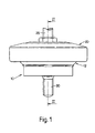
- Figure 1 is a side view of a mount according to the present invention;
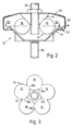
- Figure 2 is an axial section of the mount shown in Figure 1 taken along line II-II;
- Figure 3 is a sectional view of the mount shown in Figure 2 taken along line III-III; and
- Figure 4 is a graph illustrating a plot of natural frequency of a mount v static load.
- The
mount 10 includes a lowerconical seat 12 and an upperconical seat 14. Located between the upper and lower conical seats is a unitaryannular member 13. Themember 13 is preferably a one piece moulding formed from an elastomeric material having suitable resilient characteristics such as for instance natural rubber. Theannular member 13 illustrated comprises a series ofballs 15 which are closely spaced and joined at their peripheries to one another by aconnection portion 15a. Theconnection portion 15a between each pair ofballs 15 is preferably located concentrically with the point of peripheral contact between the pair of balls. In Figure 3, theannular member 13 is shown as comprising 5 balls but it will be appreciated that the annular member can comprise more or less than 5 balls. - The
annular member 13 is merely seated between the upper and lower conical seats and is not secured to either seat. - The
lower seat 12 is conveniently a metal pressing and is provided with an outwardly directedflange 18. Theupper seat 14 is secured to ahousing 20 which includes an inwardly directedflange 22.Flanges flanges balls 15 under a predetermined loading so that they are retained in a compressed state. - The
flange 22 is formed during assembly by inwardly turning the terminal marginal portion of aband 23 which forms part of thehousing 20. - The
upper seat 14 is provided with attachment means for attaching the upper seat to the machinery or structure to be mounted. In the illustrated embodiment the attachment means is in the form of a screw threadedshaft 26. - The
lower seat 12 is similarly provided with attachment means in the form of a screw threadedshaft 30 for attaching the lower seat to the support structure (not shown). - It will be appreciated that alternative types of attachment means for the upper and lower seat may be provided if desired.
- In use, the
annular member 13 acts as a bracelet ofindividual balls 15 which are able to roll relative to the upper and lower conical seats. - The resilience of the
balls 15 acts upon theconical seats central portions 15a provide relatively little resistance to twisting forces and so adjacent balls are able to roll relative to one another and in the confines of the mount act as individual balls. However, since all the balls are joined together by thecentral portions 15a it is not possible for any one of the balls to become incorrectly positioned relative to the other balls. - The ability of the mount of the present invention to progressively resist deflection as mentioned above provides greater flexibility of use applications for mount. For instance, if reference is made to the graph depicted in Figure 4 a natural frequency V static load plot is shown in a solid line of a mount having five balls of an elastomeric material having a shore hardness of 60-65.
- When mounting a machine on a structure, it is important that all the mounts have approximately the same natural frequency. Since the natural frequency of a mount is altered by the applied weight, in the past it has been necessary to calculate at the mounting locations the applied weight acting at the location and choose a mount capable of supporting that applied weight and have the desired natural frequency. As can be seen from the plot shown in Figure 4, the present mount is capable of producing a natural frequency of between 6 to 8 Hz for applied loads varying between 0.5 to 3.2 kN i.e. for a range of 2.7 kN. For comparison purposes a mount having a constant resistance to deflection is plotted (dotted line) and it will be seen that for this mount to retain a natural frequency between 6 to 8 Hz the applied load can only vary between 1.15 kN to 1.95 kN i.e. for a range of 0.8 kN.
- It will be appreciated therefore that a machine or structure to be supported can be mounted by several identical mounts of the present invention without the need to use different mounts at different locations.
Claims (5)
Priority Applications (1)
| Application Number | Priority Date | Filing Date | Title |
|---|---|---|---|
| AT86305001T ATE59444T1 (en) | 1985-07-03 | 1986-06-27 | ANTI-VIBRATION BEARING. |
Applications Claiming Priority (2)
| Application Number | Priority Date | Filing Date | Title |
|---|---|---|---|
| GB8516839 | 1985-07-03 | ||
| GB858516839A GB8516839D0 (en) | 1985-07-03 | 1985-07-03 | Anti-vibration mount |
Publications (3)
| Publication Number | Publication Date |
|---|---|
| EP0209280A2 EP0209280A2 (en) | 1987-01-21 |
| EP0209280A3 EP0209280A3 (en) | 1987-09-23 |
| EP0209280B1 true EP0209280B1 (en) | 1990-12-27 |
Family
ID=10581732
Family Applications (1)
| Application Number | Title | Priority Date | Filing Date |
|---|---|---|---|
| EP86305001A Expired - Lifetime EP0209280B1 (en) | 1985-07-03 | 1986-06-27 | Anti-vibration mount |
Country Status (4)
| Country | Link |
|---|---|
| EP (1) | EP0209280B1 (en) |
| AT (1) | ATE59444T1 (en) |
| DE (1) | DE3676578D1 (en) |
| GB (1) | GB8516839D0 (en) |
Families Citing this family (3)
| Publication number | Priority date | Publication date | Assignee | Title |
|---|---|---|---|---|
| US5005811A (en) * | 1989-10-02 | 1991-04-09 | Gencorp Inc. | Resilient rolling torus for a load-cushioning device |
| NL9000294A (en) * | 1990-02-07 | 1991-09-02 | Willy Van Goubergen | VIBRATION DAMPER. |
| GB2262467A (en) * | 1991-12-17 | 1993-06-23 | Ingersoll Rand Co | Apparatus for reducing vibration transmission in hand-held tool |
Family Cites Families (8)
| Publication number | Priority date | Publication date | Assignee | Title |
|---|---|---|---|---|
| DE1986854U (en) * | 1968-06-06 | William Gerb 6200 Wiesbaden | Rubber element for vibration isolation | |
| US1871963A (en) * | 1929-05-25 | 1932-08-16 | Inland Mfg Co | Flexible connecter |
| DE595632C (en) * | 1932-01-23 | 1934-04-16 | Emil Zorn Akt Ges | Shock-reducing pad |
| US2462011A (en) * | 1945-06-02 | 1949-02-15 | Gen Tire & Rubber Co | Cushioning support |
| US2460829A (en) * | 1945-08-01 | 1949-02-08 | Ivanovie Nicholas | Vibration insulating device |
| US2468901A (en) * | 1945-10-20 | 1949-05-03 | Gen Tire & Rubber Co | Cushioning and virration damping support |
| FR2102645A5 (en) * | 1970-08-13 | 1972-04-07 | Pineau Andre | |
| DE3225927A1 (en) * | 1982-07-10 | 1984-01-19 | Phoenix Ag, 2100 Hamburg | Elastic pivot bearing |
-
1985
- 1985-07-03 GB GB858516839A patent/GB8516839D0/en active Pending
-
1986
- 1986-06-27 EP EP86305001A patent/EP0209280B1/en not_active Expired - Lifetime
- 1986-06-27 AT AT86305001T patent/ATE59444T1/en not_active IP Right Cessation
- 1986-06-27 DE DE8686305001T patent/DE3676578D1/en not_active Expired - Fee Related
Also Published As
| Publication number | Publication date |
|---|---|
| DE3676578D1 (en) | 1991-02-07 |
| EP0209280A3 (en) | 1987-09-23 |
| EP0209280A2 (en) | 1987-01-21 |
| ATE59444T1 (en) | 1991-01-15 |
| GB8516839D0 (en) | 1985-08-07 |
Similar Documents
| Publication | Publication Date | Title |
|---|---|---|
| EP0336627B1 (en) | Resilient mounting | |
| US5743509A (en) | Elastic mount having two axially compressed elastic members | |
| US4418898A (en) | Cushioned mounting device with a mass member forming a sub-oscillation system and means for restricting cushioning movement | |
| US4958812A (en) | Suspension spring system | |
| US5074535A (en) | Elastomeric mounting | |
| EP0066815A2 (en) | Power unit mount | |
| EP0738377A1 (en) | Mounting assembly with dissimilar radial spring rates | |
| US4725046A (en) | Engine mount | |
| US4711423A (en) | Shock and vibration mount | |
| US4895115A (en) | Mount with insulation for solid-conducted sound, in particular for an internal combustion engine | |
| US3245646A (en) | All-directional shock mount | |
| EP0209280A2 (en) | Anti-vibration mount | |
| US6604735B2 (en) | Elastomer variants | |
| JP3517549B2 (en) | Anti-vibration support device | |
| US6554262B2 (en) | Wall mounted display | |
| US4504036A (en) | Engine mount preloaded in shear | |
| EP0098128A1 (en) | Improvements in or relating to resilient mountings | |
| US3263954A (en) | All-directional shock mount | |
| US5429338A (en) | Equipment mount | |
| US4821368A (en) | Eccentric shock isolation grommet | |
| US5700000A (en) | Transversely compliant body spring for a hydraulic bearing | |
| US20010030274A1 (en) | Shock and vibration mount | |
| US5934653A (en) | Nonlinear flexible connectors with streamlined resilient elements | |
| US6082698A (en) | Captive soft foam shock mount system | |
| EP0851143B1 (en) | Body mount |
Legal Events
| Date | Code | Title | Description |
|---|---|---|---|
| PUAI | Public reference made under article 153(3) epc to a published international application that has entered the european phase |
Free format text: ORIGINAL CODE: 0009012 |
|
| AK | Designated contracting states |
Kind code of ref document: A2 Designated state(s): AT BE CH DE FR GB IT LI LU NL SE |
|
| PUAL | Search report despatched |
Free format text: ORIGINAL CODE: 0009013 |
|
| AK | Designated contracting states |
Kind code of ref document: A3 Designated state(s): AT BE CH DE FR GB IT LI LU NL SE |
|
| 17P | Request for examination filed |
Effective date: 19880229 |
|
| 17Q | First examination report despatched |
Effective date: 19890120 |
|
| GRAA | (expected) grant |
Free format text: ORIGINAL CODE: 0009210 |
|
| AK | Designated contracting states |
Kind code of ref document: B1 Designated state(s): AT BE CH DE FR GB IT LI LU NL SE |
|
| REF | Corresponds to: |
Ref document number: 59444 Country of ref document: AT Date of ref document: 19910115 Kind code of ref document: T |
|
| ITF | It: translation for a ep patent filed | ||
| REF | Corresponds to: |
Ref document number: 3676578 Country of ref document: DE Date of ref document: 19910207 |
|
| ET | Fr: translation filed | ||
| ITTA | It: last paid annual fee | ||
| PLBE | No opposition filed within time limit |
Free format text: ORIGINAL CODE: 0009261 |
|
| STAA | Information on the status of an ep patent application or granted ep patent |
Free format text: STATUS: NO OPPOSITION FILED WITHIN TIME LIMIT |
|
| 26N | No opposition filed | ||
| PGFP | Annual fee paid to national office [announced via postgrant information from national office to epo] |
Ref country code: FR Payment date: 19940609 Year of fee payment: 9 |
|
| PGFP | Annual fee paid to national office [announced via postgrant information from national office to epo] |
Ref country code: AT Payment date: 19940614 Year of fee payment: 9 |
|
| PGFP | Annual fee paid to national office [announced via postgrant information from national office to epo] |
Ref country code: SE Payment date: 19940615 Year of fee payment: 9 |
|
| PGFP | Annual fee paid to national office [announced via postgrant information from national office to epo] |
Ref country code: GB Payment date: 19940617 Year of fee payment: 9 |
|
| PGFP | Annual fee paid to national office [announced via postgrant information from national office to epo] |
Ref country code: DE Payment date: 19940622 Year of fee payment: 9 |
|
| PGFP | Annual fee paid to national office [announced via postgrant information from national office to epo] |
Ref country code: CH Payment date: 19940624 Year of fee payment: 9 |
|
| PGFP | Annual fee paid to national office [announced via postgrant information from national office to epo] |
Ref country code: NL Payment date: 19940630 Year of fee payment: 9 Ref country code: LU Payment date: 19940630 Year of fee payment: 9 |
|
| EPTA | Lu: last paid annual fee | ||
| PGFP | Annual fee paid to national office [announced via postgrant information from national office to epo] |
Ref country code: BE Payment date: 19940808 Year of fee payment: 9 |
|
| EAL | Se: european patent in force in sweden |
Ref document number: 86305001.9 |
|
| PG25 | Lapsed in a contracting state [announced via postgrant information from national office to epo] |
Ref country code: LU Free format text: LAPSE BECAUSE OF NON-PAYMENT OF DUE FEES Effective date: 19950627 Ref country code: GB Effective date: 19950627 Ref country code: AT Effective date: 19950627 |
|
| PG25 | Lapsed in a contracting state [announced via postgrant information from national office to epo] |
Ref country code: SE Effective date: 19950628 |
|
| PG25 | Lapsed in a contracting state [announced via postgrant information from national office to epo] |
Ref country code: LI Effective date: 19950630 Ref country code: CH Effective date: 19950630 Ref country code: BE Effective date: 19950630 |
|
| BERE | Be: lapsed |
Owner name: ISOLATED SYSTEMS LTD Effective date: 19950630 |
|
| PG25 | Lapsed in a contracting state [announced via postgrant information from national office to epo] |
Ref country code: NL Effective date: 19960101 |
|
| GBPC | Gb: european patent ceased through non-payment of renewal fee |
Effective date: 19950627 |
|
| PG25 | Lapsed in a contracting state [announced via postgrant information from national office to epo] |
Ref country code: FR Effective date: 19960229 |
|
| REG | Reference to a national code |
Ref country code: CH Ref legal event code: PL |
|
| NLV4 | Nl: lapsed or anulled due to non-payment of the annual fee |
Effective date: 19960101 |
|
| PG25 | Lapsed in a contracting state [announced via postgrant information from national office to epo] |
Ref country code: DE Effective date: 19960301 |
|
| EUG | Se: european patent has lapsed |
Ref document number: 86305001.9 |
|
| REG | Reference to a national code |
Ref country code: FR Ref legal event code: ST |
|
| PG25 | Lapsed in a contracting state [announced via postgrant information from national office to epo] |
Ref country code: IT Free format text: LAPSE BECAUSE OF NON-PAYMENT OF DUE FEES;WARNING: LAPSES OF ITALIAN PATENTS WITH EFFECTIVE DATE BEFORE 2007 MAY HAVE OCCURRED AT ANY TIME BEFORE 2007. THE CORRECT EFFECTIVE DATE MAY BE DIFFERENT FROM THE ONE RECORDED. Effective date: 20050627 |