EP0209040A2 - Heat treatment apparatus for polyolefin resin particles - Google Patents
Heat treatment apparatus for polyolefin resin particles Download PDFInfo
- Publication number
- EP0209040A2 EP0209040A2 EP86109268A EP86109268A EP0209040A2 EP 0209040 A2 EP0209040 A2 EP 0209040A2 EP 86109268 A EP86109268 A EP 86109268A EP 86109268 A EP86109268 A EP 86109268A EP 0209040 A2 EP0209040 A2 EP 0209040A2
- Authority
- EP
- European Patent Office
- Prior art keywords
- resin particles
- heat treatment
- autoclave
- impeller
- particles
- Prior art date
- Legal status (The legal status is an assumption and is not a legal conclusion. Google has not performed a legal analysis and makes no representation as to the accuracy of the status listed.)
- Granted
Links
Images

Classifications
-
- B—PERFORMING OPERATIONS; TRANSPORTING
- B01—PHYSICAL OR CHEMICAL PROCESSES OR APPARATUS IN GENERAL
- B01J—CHEMICAL OR PHYSICAL PROCESSES, e.g. CATALYSIS OR COLLOID CHEMISTRY; THEIR RELEVANT APPARATUS
- B01J3/00—Processes of utilising sub-atmospheric or super-atmospheric pressure to effect chemical or physical change of matter; Apparatus therefor
- B01J3/04—Pressure vessels, e.g. autoclaves
-
- B—PERFORMING OPERATIONS; TRANSPORTING
- B01—PHYSICAL OR CHEMICAL PROCESSES OR APPARATUS IN GENERAL
- B01J—CHEMICAL OR PHYSICAL PROCESSES, e.g. CATALYSIS OR COLLOID CHEMISTRY; THEIR RELEVANT APPARATUS
- B01J19/00—Chemical, physical or physico-chemical processes in general; Their relevant apparatus
- B01J19/18—Stationary reactors having moving elements inside
-
- B—PERFORMING OPERATIONS; TRANSPORTING
- B29—WORKING OF PLASTICS; WORKING OF SUBSTANCES IN A PLASTIC STATE IN GENERAL
- B29B—PREPARATION OR PRETREATMENT OF THE MATERIAL TO BE SHAPED; MAKING GRANULES OR PREFORMS; RECOVERY OF PLASTICS OR OTHER CONSTITUENTS OF WASTE MATERIAL CONTAINING PLASTICS
- B29B13/00—Conditioning or physical treatment of the material to be shaped
- B29B13/02—Conditioning or physical treatment of the material to be shaped by heating
-
- B—PERFORMING OPERATIONS; TRANSPORTING
- B29—WORKING OF PLASTICS; WORKING OF SUBSTANCES IN A PLASTIC STATE IN GENERAL
- B29B—PREPARATION OR PRETREATMENT OF THE MATERIAL TO BE SHAPED; MAKING GRANULES OR PREFORMS; RECOVERY OF PLASTICS OR OTHER CONSTITUENTS OF WASTE MATERIAL CONTAINING PLASTICS
- B29B7/00—Mixing; Kneading
- B29B7/02—Mixing; Kneading non-continuous, with mechanical mixing or kneading devices, i.e. batch type
- B29B7/06—Mixing; Kneading non-continuous, with mechanical mixing or kneading devices, i.e. batch type with movable mixing or kneading devices
- B29B7/10—Mixing; Kneading non-continuous, with mechanical mixing or kneading devices, i.e. batch type with movable mixing or kneading devices rotary
- B29B7/12—Mixing; Kneading non-continuous, with mechanical mixing or kneading devices, i.e. batch type with movable mixing or kneading devices rotary with single shaft
-
- B—PERFORMING OPERATIONS; TRANSPORTING
- B01—PHYSICAL OR CHEMICAL PROCESSES OR APPARATUS IN GENERAL
- B01J—CHEMICAL OR PHYSICAL PROCESSES, e.g. CATALYSIS OR COLLOID CHEMISTRY; THEIR RELEVANT APPARATUS
- B01J2219/00—Chemical, physical or physico-chemical processes in general; Their relevant apparatus
- B01J2219/00049—Controlling or regulating processes
- B01J2219/00051—Controlling the temperature
- B01J2219/00074—Controlling the temperature by indirect heating or cooling employing heat exchange fluids
- B01J2219/00087—Controlling the temperature by indirect heating or cooling employing heat exchange fluids with heat exchange elements outside the reactor
- B01J2219/00094—Jackets
-
- B—PERFORMING OPERATIONS; TRANSPORTING
- B01—PHYSICAL OR CHEMICAL PROCESSES OR APPARATUS IN GENERAL
- B01J—CHEMICAL OR PHYSICAL PROCESSES, e.g. CATALYSIS OR COLLOID CHEMISTRY; THEIR RELEVANT APPARATUS
- B01J2219/00—Chemical, physical or physico-chemical processes in general; Their relevant apparatus
- B01J2219/18—Details relating to the spatial orientation of the reactor
- B01J2219/185—Details relating to the spatial orientation of the reactor vertical
Definitions
- This invention relates to a heat treatment apparatus for polyolefin resin particles.
- the present invention relates to an apparatus for heating and agitating polyolefin resin particles in the presence of an aqueous medium and dispersing agent in an autoclave so as to subject the resin particles to a heat treatment or an apparatus for heating and agitating polyolefin resin particles in the presence of an aqueous medium, dispersing agent and crosslinking agent in an autoclave to subject the resin particles to a heat treatment and hence to crosslinking, in which apparatus an impeller is provided over a tilted bottom wall portion of the autoclave.
- the present invention has as its object the provision of a heat treatment apparatus which can provide a number of spherical particles in a short period of time through a single-step operation by agitating particles of a polyolefin resin at an elevated temperature in an aqueous medium.
- a heat treatment apparatus equipped with an impeller over a tilted bottom wall portion of an autoclave can provide a number of spherical particles in a single-step operation without inducing fusion-cohesion and agglomeration of polyolefin resin particles upon their agitation at an elevated temperature in an aqueous medium, namely, is an economically-advantageous and efficient heat treatment apparatus for polyolefin resin particles. Based on this finding, the present invention has been brought to completion.
- a heat treatment apparatus for polyolefin resin particles said apparatus being equipped with an autoclave in which the particles are heated and agitated in the presence of an aqueous medium and dispersing agent, characterized in that said autoclave has a tilted bottom wall portion and an impeller is provided over the tilted bottom wall portion.
- the heat treatment apparatus of this invention has an advantageous effect that upon heat treatment of water-floaty particles of a polyolefin resin, the particles are prevented from gathering together above the water surface and undergoing fusion-cohesion and agglomeration.
- the heat treatment apparatus of this invention has brought about various other advantageous effects.
- the collision between the impeller and particles is reduced since the impeller is provided over the tilted bottom wall portion of the autoclave.
- a number of spherical particles can be obtained in a short period of time by a single-step operation, because the above-described development of turbulence is effective in eliminating such a conventional problem that flattened particles and/or elongated fiber-like pieces are formed due to collision of particles against the impeller.
- polyolefin resin means, for example, low-density polyethylene, medium- high density polyethylene, polypropylene, ethylene-propylene copolymers, ethylene-vinyl acetate copolymers and so on. Since particles of these resins are floaty on water, the resin particles tend to gather together on the water surface and are hence susceptible to fusion-cohesion and agglomeration when their mixing is performed in an aqueous medium by a conventional agitation method. In view of this conventional problem, an agitator 1 is provided over a tilted bottom wall portion 3 of an autoclave 2 in the present invention. This manner of agitator provision renders the stream of the aqueous mixture irregular throughout the interior of the apparatus. As a result, both horizontal and vertical streams occur in disorder and the so-called turbulence is developed, whereby the polyolefin resin particles are prevented from gathering together above the water surface and undergoing fusion cohesion and agglomeration.
- the preferable diameter-to-depth ratio of the autoclave may range from 2/1 to 1/5 with 1/1.5 - 1/3.5 being more desirable. If an autoclave having a diameter-to-depth ratio greater than 2/1 is used, it is difficult to develop sufficient turbulence because the diameter is excessively large compared with the depth. More resin particles are hence allowed to float on the liquid surface near the wall of the autoclave, thereby causing the resin particles to undergo fusion cohesion and agglomeration. If excessive agitation is applied in order to develop sufficient turbulence, there is a possible danger that the liquid surface becomes very choppy and the resin particles undergo fusion cohesion and agglomeration.
- the diameter-to-depth ratio of the autoclave is smaller than 1/5, in other words, the depth is greater compared with the diameter, the flow velocity of the liquid is lowered in an upper layer of the liquid even if the revolution speed of the impeller is increased. There is hence a danger that resin particles are allowed to float and undergo fusion cohesion and agglomeration on the surface of the liquid.
- a turbine-type impeller is desirable.
- the turbine-type impeller 1 composed of an umbrella-shaped disk 4 and vanes 5,5,... provided radially on the disk as depicted in FIGURE 2 and FIGURE 3 is most preferable.
- the number of the vanes 5 is at least 2 with 4 - 10 vanes being preferred.
- Each vane 5 may have a straight shape or as an alternative, such a curved shape as depicted in FIGURE 2.
- the diameter ratio of the turbine-type impeller to the autoclave may preferably range from 1/10 to 1/2, with 1/7 - 1/2 being more preferred.
- the ratio of the maximum height of the vanes of the turbine-type impeller to the diameter of the turbine-type impeller may preferably range from 1/1 - 1/10 with 1/2 - 1/8 being more preferred. If this ratio exceeds 1/1, vigorous agitation occurs near the impeller and resin particles are hence rendered more susceptible to deformation even when the impeller is rotated at a low speed. On the other hand, any ratios smaller than 1/10 require to increase the revolution speed in order to develop turbulence. Accordingly, resin particles have more chance to collide against vanes of the impeller and more deformed particles tend to result.
- an aqueous medium, dispersing agent and resin particles are charged in the autoclave. After heating and agitating the contents, they are cooled to obtain heat-treated resin particles.
- aqueous medium water is most preferable for its lowest price.
- Water may be used in an amount of 100 - 1000 parts by weight based on 100 parts by weight of resin particles.
- dispersing agent aluminum oxide, zinc carbonate, magnesium carbonate, calcium carbonate, calcium phosphate or the like.
- the dispersing agent may be used in an amount of 0.1 part by weight based on 100 parts by weight of resin particles.
- the apparatus of this invention can also produce crosslinked spherical particles by using a crosslinking agent along with the above-described aqueous medium, dispersing agent and resin particles.
- a crosslinking agent dicumyl peroxide, 2,5-dimethyl-2,5- dihexane (tert-butyl peroxide), di-tert-butyl perphtha- late, tert-butyl hydroperoxide or the like may be employed. It may be used in an amount of 0.01 part by weight or more based on 100 parts by weight of resin particles.
- the heating temperature may preferably range from 130°C to 170°C.
- the heating time may be chosen from 5 minutes to 8 hours or so.
- a foaming agent may also be charged in the autoclave upon effecting the above-described heat treatment or heat and crosslinking treatment of the resin particles, so that prefoamed particles can be obtained.
Landscapes
- Chemical & Material Sciences (AREA)
- Engineering & Computer Science (AREA)
- Mechanical Engineering (AREA)
- Organic Chemistry (AREA)
- Chemical Kinetics & Catalysis (AREA)
- Physics & Mathematics (AREA)
- Thermal Sciences (AREA)
- Processes Of Treating Macromolecular Substances (AREA)
- Processing And Handling Of Plastics And Other Materials For Molding In General (AREA)
- Addition Polymer Or Copolymer, Post-Treatments, Or Chemical Modifications (AREA)
- Mixers Of The Rotary Stirring Type (AREA)
Abstract
Description
- This invention relates to a heat treatment apparatus for polyolefin resin particles. Specifically, the present invention relates to an apparatus for heating and agitating polyolefin resin particles in the presence of an aqueous medium and dispersing agent in an autoclave so as to subject the resin particles to a heat treatment or an apparatus for heating and agitating polyolefin resin particles in the presence of an aqueous medium, dispersing agent and crosslinking agent in an autoclave to subject the resin particles to a heat treatment and hence to crosslinking, in which apparatus an impeller is provided over a tilted bottom wall portion of the autoclave.
- As conventional heat treatment apparatus for polyolefin resin particles, there have been employed apparatus in each of which desired one of impellers of various shapes is suspended in an autoclave so as to agitate and heat resin particles together with a dispersing agent and the like in the autoclave, whereby the resin particles are subjected to a heat treatment. Apparatus equipped with impellers, which are shown in FIGUREs 4, 5, 6 and 7 by way of example, suspended in autoclaves are used.
- When a heat treatment is applied to polyolefin resin particles, it is preferable that resulting resin particles or crosslinked resin particles are obtained with spherical shapes. The formation of these resin particles into spherical shapes has been the subject of great deal of work. It is generally required to lower the viscosity of a resin when the formation of particles of the resin into spherical shapes is desired. For this purpose, it is necessary to heat the resin to its melting point or higher. When spherical particles of crosslinked polyolefin resin are produced, it is also necessary to conduct their production at an elevated temperature (for example, the melting point of the resin or higher) so as to shorten the time required for its crosslinking reaction.
- Whenever agitation of polyolefin resin particles was attempted at such a high temperature in an aqueous medium by means of an apparatus of the above-mentioned type, it was however impossible to avoid fusion-cohesion and agglomeration of the particles so that spherical particles were difficult to obtain.
- With the foregoing drawbacks of the prior art in view, the present invention has as its object the provision of a heat treatment apparatus which can provide a number of spherical particles in a short period of time through a single-step operation by agitating particles of a polyolefin resin at an elevated temperature in an aqueous medium.
- The present inventors have carried out an extensive research in order to achieve the above-described object. As a result, it has been found that a heat treatment apparatus equipped with an impeller over a tilted bottom wall portion of an autoclave can provide a number of spherical particles in a single-step operation without inducing fusion-cohesion and agglomeration of polyolefin resin particles upon their agitation at an elevated temperature in an aqueous medium, namely, is an economically-advantageous and efficient heat treatment apparatus for polyolefin resin particles. Based on this finding, the present invention has been brought to completion.
- In one aspect of this invention, there is thus provided a heat treatment apparatus for polyolefin resin particles, said apparatus being equipped with an autoclave in which the particles are heated and agitated in the presence of an aqueous medium and dispersing agent, characterized in that said autoclave has a tilted bottom wall portion and an impeller is provided over the tilted bottom wall portion.
- Owing to the provision of the impeller over the tilted bottom wall portion of the autoclave, the stream of the particles, aqueous medium and dispersing agent become irregular in its entirety. Hence, both horizontal and vertical streams occur in disorder to develop the so-called turbulence. The heat treatment apparatus of this invention has an advantageous effect that upon heat treatment of water-floaty particles of a polyolefin resin, the particles are prevented from gathering together above the water surface and undergoing fusion-cohesion and agglomeration.
- The heat treatment apparatus of this invention has brought about various other advantageous effects. For example, the collision between the impeller and particles is reduced since the impeller is provided over the tilted bottom wall portion of the autoclave. A number of spherical particles can be obtained in a short period of time by a single-step operation, because the above-described development of turbulence is effective in eliminating such a conventional problem that flattened particles and/or elongated fiber-like pieces are formed due to collision of particles against the impeller.
- The above and other objects, features and advantages of the present invention will become apparent from the following description and the appended claims, taken in conjunction with the accompanying drawings.
-
- FIGURE 1 is a vertical cross-section of a heat treatment apparatus according to one embodiment of this invention;
- FIGURE 2 is a plan view illustrating a turbine-type impeller by way of example;
- FIGURE 3 is a schematic vertical cross-section taken along line III-III of FIGURE 2; and
- FIGURE 4 through FIGURE 7 are schematic vertical cross-sections showing conventional apparatus.
- The term "polyolefin resin" as used herein means, for example, low-density polyethylene, medium- high density polyethylene, polypropylene, ethylene-propylene copolymers, ethylene-vinyl acetate copolymers and so on. Since particles of these resins are floaty on water, the resin particles tend to gather together on the water surface and are hence susceptible to fusion-cohesion and agglomeration when their mixing is performed in an aqueous medium by a conventional agitation method. In view of this conventional problem, an agitator 1 is provided over a tilted bottom wall portion 3 of an
autoclave 2 in the present invention. This manner of agitator provision renders the stream of the aqueous mixture irregular throughout the interior of the apparatus. As a result, both horizontal and vertical streams occur in disorder and the so-called turbulence is developed, whereby the polyolefin resin particles are prevented from gathering together above the water surface and undergoing fusion cohesion and agglomeration. - In the present invention, the preferable diameter-to-depth ratio of the autoclave may range from 2/1 to 1/5 with 1/1.5 - 1/3.5 being more desirable. If an autoclave having a diameter-to-depth ratio greater than 2/1 is used, it is difficult to develop sufficient turbulence because the diameter is excessively large compared with the depth. More resin particles are hence allowed to float on the liquid surface near the wall of the autoclave, thereby causing the resin particles to undergo fusion cohesion and agglomeration. If excessive agitation is applied in order to develop sufficient turbulence, there is a possible danger that the liquid surface becomes very choppy and the resin particles undergo fusion cohesion and agglomeration.
- If the diameter-to-depth ratio of the autoclave is smaller than 1/5, in other words, the depth is greater compared with the diameter, the flow velocity of the liquid is lowered in an upper layer of the liquid even if the revolution speed of the impeller is increased. There is hence a danger that resin particles are allowed to float and undergo fusion cohesion and agglomeration on the surface of the liquid.
- As the impeller in the present invention, a turbine-type impeller is desirable. Among various turbine-type impellers, the turbine-type impeller 1 composed of an umbrella-shaped disk 4 and
vanes vanes 5 is at least 2 with 4 - 10 vanes being preferred. Eachvane 5 may have a straight shape or as an alternative, such a curved shape as depicted in FIGURE 2. - The diameter ratio of the turbine-type impeller to the autoclave may preferably range from 1/10 to 1/2, with 1/7 - 1/2 being more preferred.
- If the above ratio is smaller than 1/10, the revolution speed of the impeller has to be increased significantly in order to develop sufficient turbulence. This result in excessive turbulence in the vicinity of the impeller, whereby the resin particles collide against the impeller. As a result, deformed particles can only be obtained in some instances.
- If the above ratio exceeds 1/2, sufficient agitation can be achieved even at a low revolution speed but turbulence is difficult to develop. As a result, resin particles tend to gather above the water surface so that formation of spherical polyolefin resin particles encounters difficulties.
- Further, the ratio of the maximum height of the vanes of the turbine-type impeller to the diameter of the turbine-type impeller may preferably range from 1/1 - 1/10 with 1/2 - 1/8 being more preferred. If this ratio exceeds 1/1, vigorous agitation occurs near the impeller and resin particles are hence rendered more susceptible to deformation even when the impeller is rotated at a low speed. On the other hand, any ratios smaller than 1/10 require to increase the revolution speed in order to develop turbulence. Accordingly, resin particles have more chance to collide against vanes of the impeller and more deformed particles tend to result.
- Upon application of the apparatus according to this invention, an aqueous medium, dispersing agent and resin particles are charged in the autoclave. After heating and agitating the contents, they are cooled to obtain heat-treated resin particles.
- As the aqueous medium, water is most preferable for its lowest price. Water may be used in an amount of 100 - 1000 parts by weight based on 100 parts by weight of resin particles.
- It is possible to use, as the above-described dispersing agent, aluminum oxide, zinc carbonate, magnesium carbonate, calcium carbonate, calcium phosphate or the like. The dispersing agent may be used in an amount of 0.1 part by weight based on 100 parts by weight of resin particles.
- The apparatus of this invention can also produce crosslinked spherical particles by using a crosslinking agent along with the above-described aqueous medium, dispersing agent and resin particles. As the crosslinking agent, dicumyl peroxide, 2,5-dimethyl-2,5- dihexane (tert-butyl peroxide), di-tert-butyl perphtha- late, tert-butyl hydroperoxide or the like may be employed. It may be used in an amount of 0.01 part by weight or more based on 100 parts by weight of resin particles.
- When obtaining resin particles or crosslinked resin particles by means of the apparatus of this invention, the heating temperature may preferably range from 130°C to 170°C. On the other hand, the heating time may be chosen from 5 minutes to 8 hours or so.
- When resin particles are subjected to a heat treatment or to a heat and crosslinking treatment by means of the apparatus of this invention, a number of spherical particles can be obtained in a short period of time by a single-step operation. A foaming agent may also be charged in the autoclave upon effecting the above-described heat treatment or heat and crosslinking treatment of the resin particles, so that prefoamed particles can be obtained.
- The present invention will hereinafter be described in further detail by the following Examples and Comparative Examples.
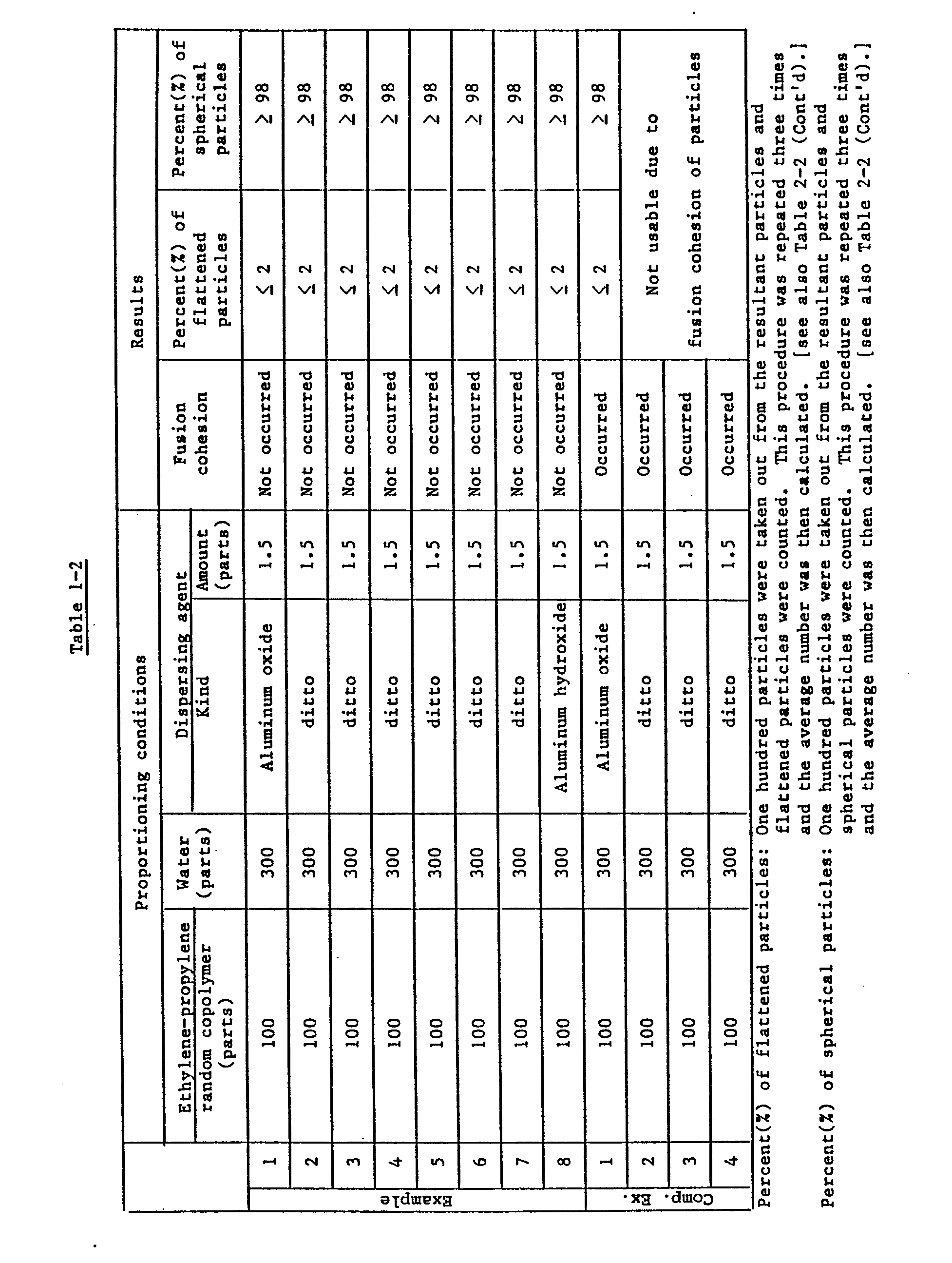
- In each of autoclaves equipped with impellers which had the same shape as that depicted in FIGURE 2 and had the corresponding dimensions shown in Table 1-1, particles of an ethylene-propylene random copolymer (melt flow index: 8.2 g/10 minutes; in the form of pellets having a density of 0.90 g/cm3, average diameter of 1.05 mm and average length of 3.0 mm) and water were charged in their corresponding amounts shown in Table 1-2. After a dispersing agent of the corresponding type and amount shown in Table 1-2 was added to the autoclave while agitating the contents of the autoclave, the autoclave was sealed. The contents of the autoclave were then maintained at 165°C for 1 hour with stirring. The autoclave was thereafter cooled and its contents were discharged. Properties of the resultant resin particles are shown in Table 1-2.
- Comparative Example 1:
- Using an autoclave having the dimensions shown in Table 1-1 and equipped with the impeller depicted in FIGURE 4, resin particles were obtained under the same conditions as in Example 6. Properties of the resultant resin particles are shown in Table 1-2. Comparative Example 2:
- Using an autoclave having the dimensions shown in Table 1-1 and equipped with the impeller depicted in FIGURE 5, resin particles were obtained under the same conditions as in Example 6. Properties of the resultant resin particles are shown in Table 1-2. Comparative Example 3:
- Using an autoclave having the dimensions shown in Table 1-1 and equipped with the impeller depicted in FIGURE 6, resin particles were obtained under the same conditions as in Example 6. Properties of the resultant resin particles are shown in Table 1-2. Comparative Example 4:
- Using an autoclave having the dimensions shown in Table 1-1 and equipped with the impeller depicted in FIGURE 7, resin particles were obtained under the same conditions as in Example 6. Properties of the resultant resin particles are shown in Table 1-2.

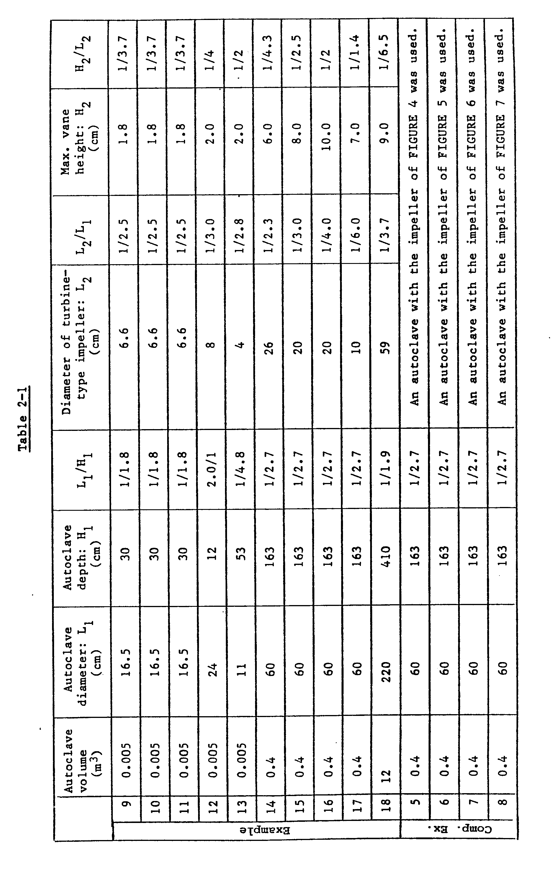
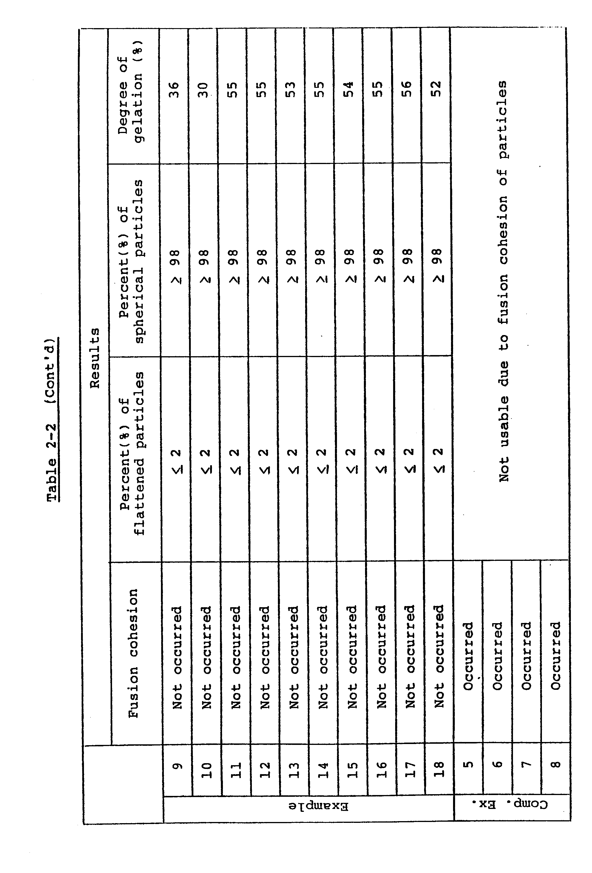
- Examples 9 - 18:
- In each of autoclaves equipped with impellers which had the same shape as that depicted in FIGURE 2 and had the corresponding dimensions shown in Table 2-1, polyolefin resin particles of the corresponding type and mount shown in Table 2-2 and water in the corresponding amount given in Table 2-2 were charged, followed by addition with stirring of a crosslinking agent of the corresponding type and amount shown in Table 2-2 and a dispersing agent of the corresponding type and amount given in Table 1-2. The autoclave was then sealed. After agitating the contents at 100°C for 1 hour, the contents were heated to 160°C at which they were maintained with agitation for 1 hour. The autoclave was thereafter cooled and its contents were discharged. Properties of the resultant resin particles are shown in Table 2-2.
- Using an autoclave having the dimensions shown in Table 2-1 and equipped with the impeller depicted in FIGURE 4, resin particles were obtained under the same conditions as in Example 14. Properties of the resultant resin particles are shown in Table 2-2. Comparative Example 6:
- Using an autoclave having the dimensions shown in Table 2-1 and equipped with the impeller depicted in FIGURE 5, resin particles were obtained under the same conditions as in Example 14. Properties of the resultant resin particles are shown in Table 2-2. Comparative Example 7:
- Using an autoclave having the dimensions shown in Table 2-1 and equipped with the impeller depicted in FIGURE 6, resin particles were obtained under the same conditions as in Example 14. Properties of the resultant resin particles are shown in Table 2-2. Comparative Example 8:
- Using an autoclave having the dimensions shown in Table 2-1 and equipped with the impeller depicted in FIGURE 7, resin particles were obtained under the same conditions as in Example 14. Properties of the resultant resin particles are shown in Table 2-2.

- Having now fully described the invention, it will be apparent to one of ordinary skill in the art that many modifications and changes can be made thereto without departing from the spirit or scope of the invention as set forth herein.
Claims (6)
Applications Claiming Priority (2)
| Application Number | Priority Date | Filing Date | Title |
|---|---|---|---|
| JP60157493A JPS6218214A (en) | 1985-07-17 | 1985-07-17 | Apparatus for heat-treating polyolefine resin particle |
| JP157493/85 | 1985-07-17 |
Publications (3)
| Publication Number | Publication Date |
|---|---|
| EP0209040A2 true EP0209040A2 (en) | 1987-01-21 |
| EP0209040A3 EP0209040A3 (en) | 1988-09-07 |
| EP0209040B1 EP0209040B1 (en) | 1990-10-03 |
Family
ID=15650891
Family Applications (1)
| Application Number | Title | Priority Date | Filing Date |
|---|---|---|---|
| EP86109268A Expired EP0209040B1 (en) | 1985-07-17 | 1986-07-07 | Heat treatment apparatus for polyolefin resin particles |
Country Status (4)
| Country | Link |
|---|---|
| US (1) | US4716021A (en) |
| EP (1) | EP0209040B1 (en) |
| JP (1) | JPS6218214A (en) |
| DE (2) | DE209040T1 (en) |
Families Citing this family (16)
| Publication number | Priority date | Publication date | Assignee | Title |
|---|---|---|---|---|
| JPH0739501B2 (en) * | 1987-06-23 | 1995-05-01 | 日本スチレンペ−パ−株式会社 | Non-crosslinked linear low density polyethylene pre-expanded particles |
| KR0146676B1 (en) * | 1994-11-14 | 1998-08-17 | 박원배 | Stirrer for suspension polymerization of vinyl chloride resins |
| EP0918066B1 (en) | 1996-08-12 | 2004-02-18 | JSP Corporation | Shock absorbing material |
| WO1998025996A1 (en) * | 1996-12-13 | 1998-06-18 | Jsp Corporation | Expanded particles of polyolefin resin and process for preparing the same |
| US20020182399A1 (en) | 1997-04-01 | 2002-12-05 | Hisao Tokoro | Molded body of thermoplastic resin having sound absorption characteristics |
| TW369475B (en) | 1997-06-18 | 1999-09-11 | Jsp Corp | Production apparatus of expansion-molded article, auxiliary member for transfer of foamed particles and production method of expansion-molded article |
| DE69827294T2 (en) | 1997-12-01 | 2006-03-09 | Jsp Corp. | EXPANDED POLYPROPYLENE RESIN PERSONS AND SHAPED ARTICLES |
| SE511230C2 (en) * | 1998-01-19 | 1999-08-30 | Novaseptic Equipment Ab | Apparatus for treating materials in a container, especially for dispersing or homogenizing liquids or suspending solids in liquids |
| SG77671A1 (en) * | 1998-03-23 | 2001-01-16 | Jsp Corp | Foamed and expanded beads of polypropylene resin for molding |
| EP0963827B1 (en) * | 1998-06-11 | 2002-10-23 | Jsp Corporation | Molded article of foamed and expanded beads of propylene resin |
| CN101985231B (en) * | 2010-11-09 | 2013-11-27 | 金发科技股份有限公司 | A particle feeder |
| DE102013018094A1 (en) * | 2013-12-03 | 2015-06-03 | Merck Patent Gmbh | Mixing device and its use |
| JP6707862B2 (en) * | 2016-01-06 | 2020-06-10 | 日立金属株式会社 | Method for producing resin composition |
| JP6564948B2 (en) | 2016-07-06 | 2019-08-21 | 株式会社カネカ | Foamed particle production apparatus for polyolefin resin particles and method for producing the foamed particles |
| RU2018136242A (en) * | 2017-10-17 | 2020-04-15 | Штефан Машинери Гмбх | DEVICE AND METHOD OF PROCESSING AND PROCESSING CHOCOLATE, AND ALSO USE OF A UNIVERSAL MACHINE FOR THIS |
| CN113348203A (en) | 2019-01-31 | 2021-09-03 | 株式会社钟化 | Apparatus and method for dehydrating expanded beads, and use thereof |
Family Cites Families (11)
| Publication number | Priority date | Publication date | Assignee | Title |
|---|---|---|---|---|
| US1613391A (en) * | 1923-08-30 | 1927-01-04 | Pfaudler Co Inc | Liquid-agitating mechanism |
| US2616340A (en) * | 1949-02-01 | 1952-11-04 | William V Knoll | Apparatus for pulping papermaking material |
| DE1910482B2 (en) * | 1969-03-01 | 1972-11-16 | Chemische Werke Hüls AG, 4370 Mari | POLYMERIZATION REACTOR |
| US4050901A (en) * | 1970-08-01 | 1977-09-27 | Chemische Werke Huls Aktiengesellschaft | Cooling unit for large polymerization vessels |
| SE344603B (en) * | 1971-06-22 | 1972-04-24 | Kamyr Ab | |
| DE2424249A1 (en) * | 1974-05-18 | 1975-11-27 | Bayer Ag | PROCESS FOR THE PRODUCTION OF POWDERED RUBBER-FILLER BATCHES |
| US4125697A (en) * | 1976-05-05 | 1978-11-14 | Bayer Aktiengesellschaft | Process for the production of polychloroprene |
| DE2852622C2 (en) * | 1978-12-05 | 1982-09-09 | Wacker-Chemie GmbH, 8000 München | Polymerization autoclave |
| DE3026492A1 (en) * | 1980-07-12 | 1982-02-04 | Wilhelm Hedrich Vakuumanlagen GmbH und Co KG, 6332 Ehringshausen | DEVICE FOR MIXING AND DEGASSING COMPONENTS OF SYNTHETIC RESINS, ESPECIALLY DUROPLASTIC RESINS |
| JPS5753505U (en) * | 1980-09-13 | 1982-03-29 | ||
| EP0140059B1 (en) * | 1983-09-08 | 1988-06-08 | Kanegafuchi Kagaku Kogyo Kabushiki Kaisha | Pre-expanding process and apparatus for the same |
-
1985
- 1985-07-17 JP JP60157493A patent/JPS6218214A/en active Granted
-
1986
- 1986-07-07 DE DE198686109268T patent/DE209040T1/en active Pending
- 1986-07-07 EP EP86109268A patent/EP0209040B1/en not_active Expired
- 1986-07-07 DE DE8686109268T patent/DE3674657D1/en not_active Expired - Lifetime
- 1986-07-09 US US06/883,655 patent/US4716021A/en not_active Expired - Lifetime
Also Published As
| Publication number | Publication date |
|---|---|
| JPH0544326B2 (en) | 1993-07-06 |
| EP0209040A3 (en) | 1988-09-07 |
| DE209040T1 (en) | 1987-05-21 |
| EP0209040B1 (en) | 1990-10-03 |
| DE3674657D1 (en) | 1990-11-08 |
| JPS6218214A (en) | 1987-01-27 |
| US4716021A (en) | 1987-12-29 |
Similar Documents
| Publication | Publication Date | Title |
|---|---|---|
| EP0209040B1 (en) | Heat treatment apparatus for polyolefin resin particles | |
| US4056653A (en) | Spherical-shaped particles from ionomer resins and ethylene/carboxylic acid copolymer resins | |
| US3933954A (en) | Preparation of powders having spherical-shaped particles from ionomer resins and ethylene/carboxylic acid copolymer resins | |
| JP2539956B2 (en) | Method for producing fluid-stable granules | |
| US4217145A (en) | Process for admixing polymer emulsions with water to produce highly viscous liquids | |
| US5556820A (en) | Catalyst component for olefin polymerization and process for producing polyolefins | |
| US3663657A (en) | Emulsion-suspension graft copolymerization process | |
| US4048257A (en) | Pigmentable low shrink thermosetting polyesters | |
| FI96957C (en) | Process for mass polymerization of vinyl chloride | |
| US3652453A (en) | Defoamer composition | |
| CA1203345A (en) | Method of continuous polymerization in fluidized bed | |
| ES8307840A1 (en) | Polymerisation process in the gaseous state with heterogeneous catalysis, and spherical reactor for putting it into use. | |
| JPH0248027A (en) | Agitating pot with radially fed agtator and at least one buffer and method for mixing liquid by using agtating pot | |
| EP0324385B1 (en) | Process for preparing waterswellable polymers using sodium thiosulfate as part of a redox initiator system | |
| EP0044960B1 (en) | Process for encapsulating wastes in vinyl-ester resins, unsaturated polyester resins or mixtures thereof | |
| EP1937752A1 (en) | Method for preparing high molecule latex resin powder | |
| US3935093A (en) | Bitumen blowing | |
| JPS58204396A (en) | Method of sealing liquid waste in liquid heat curable resin | |
| US2854320A (en) | Polymerization reaction vessel | |
| US4029863A (en) | Method of obtaining small particle size polymers and copolymers of vinyl chloride by bulk polymerization | |
| CA1127791A (en) | Method of suspension polymerization and apparatus therefor | |
| US2108044A (en) | Plastic materials and to methods of production thereof | |
| JP3146371B2 (en) | Coagulation reaction device | |
| DE3813363A1 (en) | MIXTURES OF THERMOPLASTIC POLYMERISATE IN POWDER FORM | |
| US5243007A (en) | Polymers based on vinyl chloride prepared by mass polymerization |
Legal Events
| Date | Code | Title | Description |
|---|---|---|---|
| PUAI | Public reference made under article 153(3) epc to a published international application that has entered the european phase |
Free format text: ORIGINAL CODE: 0009012 |
|
| AK | Designated contracting states |
Kind code of ref document: A2 Designated state(s): DE FR GB |
|
| EL | Fr: translation of claims filed | ||
| DET | De: translation of patent claims | ||
| PUAL | Search report despatched |
Free format text: ORIGINAL CODE: 0009013 |
|
| AK | Designated contracting states |
Kind code of ref document: A3 Designated state(s): DE FR GB |
|
| 17P | Request for examination filed |
Effective date: 19881005 |
|
| 17Q | First examination report despatched |
Effective date: 19890303 |
|
| GRAA | (expected) grant |
Free format text: ORIGINAL CODE: 0009210 |
|
| AK | Designated contracting states |
Kind code of ref document: B1 Designated state(s): DE FR GB |
|
| REF | Corresponds to: |
Ref document number: 3674657 Country of ref document: DE Date of ref document: 19901108 |
|
| ET | Fr: translation filed | ||
| PLBE | No opposition filed within time limit |
Free format text: ORIGINAL CODE: 0009261 |
|
| STAA | Information on the status of an ep patent application or granted ep patent |
Free format text: STATUS: NO OPPOSITION FILED WITHIN TIME LIMIT |
|
| 26N | No opposition filed | ||
| REG | Reference to a national code |
Ref country code: GB Ref legal event code: IF02 |
|
| PGFP | Annual fee paid to national office [announced via postgrant information from national office to epo] |
Ref country code: DE Payment date: 20050630 Year of fee payment: 20 |
|
| PGFP | Annual fee paid to national office [announced via postgrant information from national office to epo] |
Ref country code: GB Payment date: 20050706 Year of fee payment: 20 |
|
| PGFP | Annual fee paid to national office [announced via postgrant information from national office to epo] |
Ref country code: FR Payment date: 20050708 Year of fee payment: 20 |
|
| PG25 | Lapsed in a contracting state [announced via postgrant information from national office to epo] |
Ref country code: GB Free format text: LAPSE BECAUSE OF EXPIRATION OF PROTECTION Effective date: 20060706 |
|
| REG | Reference to a national code |
Ref country code: GB Ref legal event code: PE20 |