EP0208901B1 - Device for nebulizing sample-liquid for spectroscopical purposes - Google Patents
Device for nebulizing sample-liquid for spectroscopical purposes Download PDFInfo
- Publication number
- EP0208901B1 EP0208901B1 EP86107757A EP86107757A EP0208901B1 EP 0208901 B1 EP0208901 B1 EP 0208901B1 EP 86107757 A EP86107757 A EP 86107757A EP 86107757 A EP86107757 A EP 86107757A EP 0208901 B1 EP0208901 B1 EP 0208901B1
- Authority
- EP
- European Patent Office
- Prior art keywords
- nozzle
- pump
- set forth
- pressure
- pressure pump
- Prior art date
- Legal status (The legal status is an assumption and is not a legal conclusion. Google has not performed a legal analysis and makes no representation as to the accuracy of the status listed.)
- Expired - Lifetime
Links
Images


Classifications
-
- G—PHYSICS
- G01—MEASURING; TESTING
- G01N—INVESTIGATING OR ANALYSING MATERIALS BY DETERMINING THEIR CHEMICAL OR PHYSICAL PROPERTIES
- G01N21/00—Investigating or analysing materials by the use of optical means, i.e. using sub-millimetre waves, infrared, visible or ultraviolet light
- G01N21/62—Systems in which the material investigated is excited whereby it emits light or causes a change in wavelength of the incident light
- G01N21/71—Systems in which the material investigated is excited whereby it emits light or causes a change in wavelength of the incident light thermally excited
- G01N21/714—Sample nebulisers for flame burners or plasma burners
Definitions
- the atomized sample liquid can be sprayed into the mixing chamber of a burner for atomic absorption spectroscopy.
- a device of this type can also be used to spray sample liquid into the plasma of a plasma torch for plasma emission spectroscopy.
- Pneumatic atomizers are usually used to atomize the sample liquid.
- Such pneumatic atomizers contain a nozzle from which a stream of compressed gas emerges. Coaxially in this nozzle is a tube through which the sample liquid is fed.
- the sample liquid When the sample liquid enters the compressed gas flow, the sample liquid is torn into droplets due to the speed differences between the sample liquid and compressed gas flow.
- the sample liquid is first atomized into an atomizing chamber or mixing chamber. The larger droplets are deposited in this, while only the small droplets are carried away to the flame or the plasma.
- the gas pressure is two to six bar. Higher gas pressures and thus higher flow velocities of the gas flow lead to too much gas in the flame or the plasma. A finer atomization results.
- the aerosol is very heavily diluted with air or inert gas. This affects the function of the flame or the plasma. In addition, the sensitivity is reduced by the dilution of the aerosol.
- a device for atomizing sample liquid for spectroscopic purposes which works with a conventional pneumatic atomizer.
- a compressor is provided there, which is connected to the atomizer via a line.
- the compressor generates compressed air there, the pressure of which is regulated by a pressure regulator.
- This compressed air exits at high speed as an annular stream through an atomizing nozzle.
- sample liquid is drawn in from a container.
- the sample liquid is atomized by the high flow velocity of the air surrounding the sample liquid thus drawn in.
- DE-OS 30 10 350 discloses a laminar burner for spectroscopic purposes, in which a liquid sample is drawn in and atomized into a mixing chamber, mixed with oxidant and fuel gas in the mixing chamber and fed to a burner head as an aerosol.
- a mechanical atomizer is provided for atomizing the sample, in which the sample liquid is sucked in by a pump, brought under pressure and atomized via a valve nozzle.
- the atomizer has a cylinder with a through hole in which a sample suction line opens laterally.
- a plunger is guided in the through hole and protrudes from the through hole on one side.
- a valve nozzle sits on the other side of the through hole.
- the valve nozzle consists of a valve cone which sits under the influence of a preloaded spring on the mouth of the through hole.
- a cap with a central nozzle opening is screwed onto the cylinder and engages over the valve cone.
- the plunger is set in rapid reciprocating motion by a drive device.
- the atomizer has a cylinder with a stepped through-bore which has an enlarged part at one end of the cylinder and a part of smaller diameter at the other end, a shoulder being formed between the two parts.
- a sample suction line opens into the part of smaller diameter at a short distance from the shoulder.
- a plunger is guided, which protrudes from the through hole on one side.
- a narrow outlet nozzle closes off the extended part of the through hole.
- a valve body preloaded in the closing direction sits on the shoulder.
- the plunger piston can be made to move back and forth quickly by a drive device.
- Such an arrangement has the advantage that no additional gas flow is required to atomize the sample liquid.
- the pump and nozzle form a structural unit. So the pump must be mounted directly on the burner together with the nozzle and the drive of the pump. This poses constructive difficulties.
- the known atomizer there is also a difficult to control pulsation of the sprayed-in sample liquid mist, which, as explained there, is to be smoothed out by the mixing chamber. A pulsation of the flow velocity also leads to a pulsation of the droplet sizes.
- sample liquid is supplied from a pump designed as a separate assembly via a capillary to a narrow outlet opening which is arranged on the inlet side of the channel and is aligned in the longitudinal direction of the channel.
- the outlet opening has a diameter of 0.025 mm, i.e. an outlet cross section of approximately 5 - 10 m 2 .
- the pump delivers a pressure of approximately 2 bar. This creates a jet of droplets that runs along the axis of the channel. The droplets have an initial diameter of about 50 pm, which decreases on the way through the channel due to evaporation.
- the pump works with a relatively low pressure. Accordingly, droplets with a relatively large diameter also occur. This is also necessary according to the conception of DE-A-2 144 642. A droplet jet is supposed to be generated there, which does not touch the wall of the channel. This would not be achieved if the escaping liquid were torn into an extremely fine mist.
- a sample vessel is arranged with a sample solution in a pressure vessel.
- a hose line is immersed in the sample solution and is sealed out of the pressure vessel.
- the hose line leads to a corundum nozzle with an outlet opening of 25 pm.
- the outlet cross section is also about 5 here. 10-10 m 2 .
- the pressure in the pressure vessel which pushes the sample solution through the hose line and the nozzle, is also only a few bar here, so it is relatively low. This pressure is not sufficient to tear the sample solution into an aerosol as required. Rather, a sample jet emerges from the nozzle. This sample beam hits a baffle plate. The jet is atomized into the required aerosol by the baffle plate.
- High pressure pumps are described in the book by Snyder and Kirkland "Introduction to Modern Liquid Chromatography” 2nd edition (1979), John Wiley & Sons, New York, pages 90-101, 113, 114, which sample fluid at high pressure of more than Can bring 30 bar.
- a carrier liquid with this high pressure is pumped through a chromatographic separation column.
- a loop containing the sample liquid can be switched into the carrier liquid stream by means of a changeover valve, so that the sample liquid is transported through the separation column by the carrier liquid stream.
- the various constituents of the sample liquid migrate through the separation column at different speeds as a result of interaction with the separation column and appear one after the other at the exit thereof.
- the invention has for its object to provide a device for atomizing sample liquid for spectroscopic purposes, which allows a defined atomization of the sample liquid with a high yield of very small droplets and their use in burners, plasma torches or other excitation and atomization devices in spectroscopy is possible without constructive problems.
- the pump is a high pressure pump for generating a minimum pressure of 30 bar.
- High-pressure pumps are commercially available, for example, as high-pressure pumps for high-pressure liquid chromatography (HPLC). You deliver one constant, non-pulsating pressure. As a result, the droplet size, which depends on this pressure, remains constant. The high pressure and the small nozzle opening ensure a high exit speed and thus a fine atomization of the sample liquid with a high proportion of very small droplets.
- the aerosol thus obtained can be introduced into a flame or into the plasma of a plasma torch without further measures, in contrast to DE-A-2 144 642, where additional heating is provided, or to the publication by Doherty and Hieftje discussed above, where the actual aerosol formation takes place on a baffle.
- the nozzle is so small that even small amounts of sample can be sprayed in over a sufficiently long measuring time at the high pressure.
- Embodiments of the invention are the subject of the dependent claims.
- 10 denotes a burner which has a mixing chamber 12 and a burner head 14.
- a flame 16 burns on the burner head 14.
- a fuel gas for example acetylene
- a fuel gas is fed into the mixing chamber 12 via a connection 18 and air is supplied via a connection 20. Air and fuel gas mix in the mixing chamber 12.
- a liquid mist is sprayed into the mixing chamber 12 from a nozzle 22. Liquid condensate from the liquid mist deposited in the mixing chamber 12 can run off via an outlet 23.
- the gases supplied via the connections 18 and 20 transport the liquid mist generated by the nozzle 22 into the flame.
- the device for atomizing sample liquid contains a high pressure pump 2 and the nozzle 22.
- the high pressure pump 24 and nozzle 22 are connected to one another by line means 26.
- the high-pressure pump 24 is a two-piston pump, as is commercially available for high-pressure liquid chromatography.
- a pump that can be used for this purpose is sold by the company LDC / Milton Roy in Riviera Beach, Florida 33404 USA, under the trademark "consta-Metric 111".
- Such a high-pressure pump delivers a pulse-free, stabilized pressure at flow rates of 0.1 to 9.99 ml / min with a flow rate stability of ⁇ 0.3% / hour and a maximum pressure of approx. 410 bar (6,000 psi).
- the pump 24 draws liquid from a container 27 through a filter 30 upstream of the inlet 28 of the pump 24.
- An outlet 32 of the high pressure pump 24 is connected to the nozzle 22 via the line means 26.
- the line means 26 include a high pressure capillary 34.
- the line means 26 between the outlet 32 of the high pressure pump 24 and the nozzle 22 contain a loop which can be filled with a sample liquid as well as changeover valve means through which the loop can selectively flow into the flow path between the high pressure pump 24 and nozzle can be switched on.
- These switching valve means with a loop are represented by block 36 in FIG. 1.
- These can be components as are also known from high-pressure liquid chromatography. Examples of such valves are described in the company publication "Das Chrompack Chromatographie-Handbuch Generalkatalog" by Chrompack, 4330 AA Middelburg, Netherlands, pages 136-140.
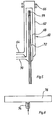
- the nozzle 22 is shown enlarged in FIG. 2.
- the liquid enters the interior 38 of the nozzle 22 and from there to a narrow outlet opening 40.
- the connection between the high-pressure capillary 34 and the nozzle 22 takes place through a conventional high-pressure connection 42, as is also known, for example, from high-pressure liquid chromatography.
- the high pressure pump works with a pressure of more than 30 bar.
- the nozzle has a diameter of less than 40 pm, ie the smallest flow cross section of the nozzle is less than 1.3.10-9 m 2 .
- sample liquid When sample liquid is drawn in by the high-pressure pump 24 from the container 27, a relatively large amount of sample liquid is consumed, since, for example, the pump cylinders have to be filled with sample liquid. So much sample liquid is often not available. Another problem is that sample liquids are often aggressive, so there is a risk of damage to the high pressure pump 24. Finally, there is a risk of carry-over in the case of successive measurements of different samples.
- the container 27 contains pure solvent. This solvent is put under high pressure by the high pressure pump 24.
- the sample is filled into the loop, which can be switched on by the changeover valve means 36 into the flow connection between high pressure pump 24 and nozzle 22 in response to a changeover command.
- the sample liquid is thereby brought to the high outlet pressure of the high-pressure pump 24 indirectly, namely via the pumped solvent, and pressed by the solvent through the nozzle 22.
- This arrangement has the advantage that the high pressure pump 24 only comes into contact with a solvent. The risk of carry-over of the sample and the risk of corrosion of the high-pressure pump 24 by aggressive samples is thereby avoided. Only device 36, high-pressure capillary 34 and nozzle 22 need to be corrosion-resistant.
- the loop like the high-pressure capillary 34, is rinsed by the subsequent pure solvent after the sample has passed through, so that the risk of carryover is avoided.
- a filter between the switching valve means 36 and the nozzle 22.
- Such a filter is indicated by dashed lines in FIG. 1 and designated 31.
- a high-pressure pump 40 which can be constructed similarly to the pump 24 of FIG. 1 and is designed to generate a continuous liquid flow at constant pressure, draws liquid in from a container 46 via an inlet 42 and a filter 44.
- An outlet 48 of the high pressure pump 40 is connected to a controlled valve 50.
- This controlled valve can be actuated by an electronic control device 52 with a large number of cycles (e.g. 10 to 100 / s), so that the liquid flow is pulsed at this frequency.
- the valve is preferably an electromagnetic needle valve. The liquid flow generated in this way is directed onto the nozzle 54.
- This arrangement has the advantage that at a given mean flow rate, for example of 1 ml / min., Higher pressures can be used with the same nozzle diameters. An increase in pressure with the same nozzle diameter to achieve a higher exit velocity of the sample liquid at the nozzle and thus a finer atomization would lead to a corresponding increase in the flow rate and thus a rapid consumption of the sample liquid under continuous pressure.
- the pressure can be increased without the mean flow rate exceeding a predetermined value.
- the arrangement according to FIG. 3 differs from an arrangement approximately according to DE-OS 30 10 350, in which the pump delivers a pulsating pressure and therefore larger droplets are formed in the mist of sample liquid in the range of low pressures.
- the arrangement according to FIG. 3, like the arrangement according to FIG. 1, can be used in two different ways. Sample liquid can be sucked out of the container 46 immediately. However, it is also possible to introduce the sample in a loop which is switched into the flow path between valve 50 and nozzle 54 by switching valve means. The loop and the switching valve means are again represented by a block 56 in FIG. 3.
- valve 50 and the loop and switching valve means 56 can also be interchanged.
- the high pressure pump 40 can be connected to the electronic control unit 52 for synchronization.
- the high pressure pump is a high pressure pulse generator 58 through which a predetermined volume in the microliter range (e.g. 50 ⁇ l) of sample liquid is forced through the nozzle 22 in a short time interval.
- the high-pressure pulse generator 58 is connected directly to the nozzle 22 by line means 60.
- the nozzle 22 sits in the wall of a mixing chamber 12 of a burner 10, which is constructed in the same way as the burner 10 of FIG. 1. Corresponding parts have the same reference numerals in FIGS. 1 and 4.
- the aerosol is sprayed directly into the plasma of a plasma torch 60 from a nozzle 59.
- the nozzle 59 is arranged centrally in the plasma torch 60.
- the plasma torch 60 has an outer tube 62 which is open at one end and to which a noble gas to be ionized in the form of argon is fed via a connection 64.
- the outer tube 62 is surrounded by an excitation coil 66 at its open end.
- the plasma torch 60 also has an inner tube 68 which is coaxial with the outer tube 62 and which ends below the excitation coil 66.
- Noble gas also in the form of argon, is passed as a coolant through the inner tube 68 via a connection 70.
- a capillary 72 is guided coaxially within the inner ear 68 and is connected in the manner of FIGS. 1, 3 or 4 to a high-pressure pump (not shown) and carries the nozzle 59 at its end.
- a nozzle 74 is attached directly to a tube furnace 76.
- the tube furnace 76 may be a quartz tube in the flame of a burner for atomic absorption spectroscopy. However, it can also be a tube which is heated in the manner of a graphite tube cell by electrical resistance heating. The interior of the tube furnace forms a defined absorption volume in atomic absorption spectrometry.
- the sample liquid under high pressure can be supplied to the nozzle 74 in any of the ways shown in Figs. 1, 3 and 4.
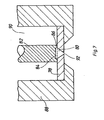
- Fig. 7 shows an advantageous construction of a nozzle used in the device described.
- the nozzle is designed as a so-called "hollow cone nozzle".
- the advantage of such a hollow cone nozzle is that the narrowest point for generating a high speed of the liquid to be atomized is inside the nozzle.
- the actual atomizing opening e.g. the outlet opening to the mixing chamber 12 (Fig. 1) may be relatively large, e.g. have a diameter of 100 pm.
- a hollow cone 80 is formed in a plate 78.
- the hollow cone 80 is closed at the top by a cylinder 82 which has a recess 84 in its end face.
- a tangential inlet opening 86 of minimal diameter is notched at one point of the cylinder 82.
- the notch has a conical shape, i.e. it is narrow at the entry point into the hollow cone 80. for example with a diameter of 20 pm while being large on the side of the liquid inlet, e.g. has a diameter of 100 pm.
- the plate 78 is held by a housing 88.
- the cylinder 82 provides the necessary pressure of the plate 78 against the housing 88.
- the liquid from the pump 24 under high pressure is located in the space 90 between the cylinder 82 and the housing 88, reaches the hollow cone 80 via the inlet opening 86 and is applied an outlet opening 92 atomized.
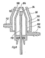
- FIG. 8 shows an arrangement in which the nozzle 94, which is acted upon by sample liquid under high pressure, is arranged centrally in a so-called “turbulence burner”.
- a turbulence burner contains an outer jacket 96 with a conically tapered upper end 98.
- an inner jacket 100 is also arranged with a conically tapered upper end 102.
- the inner casing 100 forms a narrow outlet opening 104 at the top.
- An annular space 106 is formed between the outer casing 96 and the inner casing 100. The annular space 106 ends in a scribe slot 108 between the tapered ends 98 and 102.
- a capillary 110 is seated coaxially in the inner jacket 100 and carries the nozzle 94 at its end, just below the outlet opening.
- the annular space 106 can be connected to a fuel gas source via a connection 112.
- the interior of the inner jacket 100 can be connected via a connection 114 to a source of oxidant.
- Such turbulence burners usually have the disadvantage that a large number of large droplets get into the flame. This means that the evaporation is only incomplete and the spectral background is considerably enlarged. If, however, a pressure-resistant capillary 110, which carries the nozzle 94 at its upper end, is used in such a turbulence burner instead of the conventional suction capillary, the essential disadvantages of the turbulence burner are overcome.
- the advantages come into play, e.g. that the sample gets completely into the flame.
Description
Die Erfindung betrifft eine Vorrichtung zum Zerstäuben für spektroskopische Zwecke, enthaltend
- (a) eine als gesonderte Baugruppe ausgebildete Pumpe und
- (b) eine mit der Pumpe über Leitungsmittel verbundene Düse mit einem kleinsten Strömungsquerschnitt von weniger als 5 -10-9 m2, wobei die zu zerstäubende Probenflüssigkeit von der Pumpe durch die Düse gepumpt wird.
- (a) a pump designed as a separate assembly and
- (b) a nozzle connected to the pump via line means with a smallest flow cross section of less than 5 -10-9 m 2 , the sample liquid to be atomized being pumped through the nozzle by the pump.
Die zerstäubte Probenflüssigkeit kann dabei in die Mischkammer eines Brenners für die Atomabsorptions-Spektroskopie eingesprüht werden. Eine Vorrichtung dieser Art kann jedoch auch benutzt werden, um Probenflüssigkeit in das Plasma eines Plasmabrenners für die Plasmaemissions-Spektroskopie einzusprühen.The atomized sample liquid can be sprayed into the mixing chamber of a burner for atomic absorption spectroscopy. However, a device of this type can also be used to spray sample liquid into the plasma of a plasma torch for plasma emission spectroscopy.
Für diese Zwecke ist man bemüht, ein möglichst fein verteiltes Aerosol zu erzeugen, also ein Aerosol bei welchem die gebildeten Tröpfchen überwiegend sehr klein sind. Größere Tröpfchen werden nicht oder nur unvollständig verdampft, so daß Probensubstanz für die Messung verloren geht. Außerdem wird durch Streuung, Reflexion und Brechung der Strahlung an den Tröpfchen der Rauschpegel erhöht.For these purposes, efforts are made to produce an aerosol that is as finely divided as possible, that is, an aerosol in which the droplets formed are predominantly very small. Larger droplets are not or only partially evaporated, so that sample substance is lost for the measurement. In addition, the noise level is increased by the scattering, reflection and refraction of the radiation at the droplets.
Üblicherweise werden zum Zerstäuben der Probenflüssigkeit pneumatische Zerstäuber verwendet. Solche pneumatischen Zerstäuber enthalten eine Düse, aus welcher ein Druckgasstrom austritt. Koaxial in dieser Düse sitzt ein Rohr, über welches die Probenflüssigkeit zugeführt wird. Bei Eintritt der Probenflüssigkeit in den Druckgasstrom wird die Probenflüssigkeit infolge der Geschwindigkeitsunterschiede von Probenflüssigkeits- und Druckgasstrom zu Tröpfchen zerrissen. Bei solchen Zerstäubern wird nur ein relativ geringer Prozentsatz der Probenflüssigkeit zu hinreichend kleinen Tröpfchen zerstäubt. Um größere Tröpfchen von der Flamme oder dergleichen fernzuhalten, wird die Probenflüssigkeit zunächst in eine Zerstäubungskammer oder Mischkammer zerstäubt. In dieser schlagen sich die größeren Tröpfchen nieder, während nur die kleinen Tröpfchen zu der Flamme oder dem Plasma mitgerissen werden.Pneumatic atomizers are usually used to atomize the sample liquid. Such pneumatic atomizers contain a nozzle from which a stream of compressed gas emerges. Coaxially in this nozzle is a tube through which the sample liquid is fed. When the sample liquid enters the compressed gas flow, the sample liquid is torn into droplets due to the speed differences between the sample liquid and compressed gas flow. With such atomizers, only a relatively small percentage of the sample liquid is atomized into sufficiently small droplets. In order to keep larger droplets away from the flame or the like, the sample liquid is first atomized into an atomizing chamber or mixing chamber. The larger droplets are deposited in this, while only the small droplets are carried away to the flame or the plasma.
Bei üblichen pneumatischen Zerstäubern beträgt der Gasdurck zwei bis sechs bar. Höhere Gasdrücke und damit höhere Strömungsgeschwindigkeiten des Gasstromes führen der Flamme bzw. dem Plasma zu viel Gas zu. Es ergibt sich zwar eine feinere Zerstäubung. Das Aerosol wird jedoch sehr stark mit Luft bzw. Edelgas verdünnt. Das beeinträchtigt die Funktion der Flamme bzw. des Plasmas. Außerdem wird durch die Verdünnung des Aerosols die Empfindlichkeit herabgesetzt.With conventional pneumatic atomizers, the gas pressure is two to six bar. Higher gas pressures and thus higher flow velocities of the gas flow lead to too much gas in the flame or the plasma. A finer atomization results. However, the aerosol is very heavily diluted with air or inert gas. This affects the function of the flame or the plasma. In addition, the sensitivity is reduced by the dilution of the aerosol.
Durch die DE-PS 1 950 989 ist eine Vorrichtung zum Zerstäuben von Probenflüssigkeit für spektroskopische Zwecke bekannt, die mit einem üblichen pneumatischen Zerstäuber arbeitet. Es ist dort ein Kompressor vorgesehen, der mit dem Zerstäuber über eine Leitung verbunden ist. Der Kompressor erzeugt dort Druckluft, deren Druck durch einen Druckregler geregelt wird. Diese Druckluft tritt mit hoher Geschwindigkeit als ringförmiger Strom durch eine Zerstäuberdüse aus. Dabei wird infolge des erzeugten Unterdrucks Probenflüssigkeit aus einem Behälter angesaugt. Die Zerstäubung der Probenflüssigkeit erfolgt durch die hohe Strömungsgeschwindigkeit der die so angesaugte Probenflüssigkeit umgebenden Luft.From DE-PS 1 950 989 a device for atomizing sample liquid for spectroscopic purposes is known, which works with a conventional pneumatic atomizer. A compressor is provided there, which is connected to the atomizer via a line. The compressor generates compressed air there, the pressure of which is regulated by a pressure regulator. This compressed air exits at high speed as an annular stream through an atomizing nozzle. As a result of the negative pressure generated, sample liquid is drawn in from a container. The sample liquid is atomized by the high flow velocity of the air surrounding the sample liquid thus drawn in.
Es ist weiterhin bekannt (Zeitschrift "Industrie-Lackierbetrieb", 44 Jahrgang (1976) Nr. 6 Seiten 222-229), Lack mittels einer Spritzpistole zu zerstäuben, indem der Lack von einer Hochdruckpumpe durch eine Düse gepumpt wird.It is also known (magazine "Industrie-Lackierbetrieb", 44 year (1976) No. 6 pages 222-229) to atomize paint by means of a spray gun, in that the paint is pumped through a nozzle by a high-pressure pump.
Durch die DE-OS 30 10 350 ist ein Laminarbrenner für spektroskopische Zwecke bekannt, bei welchem eine flüssige Probe angesaugt und in eine Mischkammer zerstäubt, in der Mischkammer mit Oxidans und Brenngas gemischt und als Aerosol einem Brennerkopf zugeführt wird. Bei diesem Laminarbrenner ist zum Zerstäuben der-Probe ein mechanischer Zerstäuber vorgesehen, bei welchem die Probenflüssigkeit durch eine Pumpe angesaugt, unter Druck gebracht und über eine Ventildüse vernebelt wird. Der Zerstäuber weist einen Zylinder mit einer Durchgangsbohrung auf, in welcher seitlich eine Probenansaugleitung mündet. In der Durchgangsbohrung ist ein Plungerkolben geführt, der auf einer Seite aus der Durchgangsbohrung herausragt. Auf der anderen Seite der Durchgangsbohrung sitzt eine Ventildüse. Die Ventildüse besteht aus einem Ventilkegel der unter dem Einfluß einer vorbelasteten Feder auf der Mündung der Durchgangsbohrung aufsitzt. Auf den Zylinder ist eine mit einer zentralen Düsenöffnung versehene Kappe aufgeschraubt, welche über den Ventilkegel greift. Durch eine Antriebsvorrichtung wird der Plungerkolben in schnelle hin- und hergehende Bewegung versetzt.DE-OS 30 10 350 discloses a laminar burner for spectroscopic purposes, in which a liquid sample is drawn in and atomized into a mixing chamber, mixed with oxidant and fuel gas in the mixing chamber and fed to a burner head as an aerosol. In this laminar burner, a mechanical atomizer is provided for atomizing the sample, in which the sample liquid is sucked in by a pump, brought under pressure and atomized via a valve nozzle. The atomizer has a cylinder with a through hole in which a sample suction line opens laterally. A plunger is guided in the through hole and protrudes from the through hole on one side. A valve nozzle sits on the other side of the through hole. The valve nozzle consists of a valve cone which sits under the influence of a preloaded spring on the mouth of the through hole. A cap with a central nozzle opening is screwed onto the cylinder and engages over the valve cone. The plunger is set in rapid reciprocating motion by a drive device.
Bei einer anderen Ausführungsform der DE-OS 3010350 weist der Zerstäuber einen Zylinder mit einer gestuften Durchgangsbohrung auf, die an einem Ende des Zylinders einen erweiterten Teil und am anderen Ende einen Teil von geringerem Durchmesser besitzt, wobei zwischen den beiden Teilen eine Schulter gebildet ist. Eine Probenansaugleitung mündet in den Teil von geringerem Durchmesser in geringem Abstand von der Schulter. In diesem Teil der Durchgangsbohrung ist ein Plungerkolben geführt, der auf einer Seite aus der Durchgangsbohrung herausragt. Eine enge Austrittsdüse schließt den erweiterten Teil der Durchgangsbohrung ab. Auf der Schulter sitzt ein in Schließrichtung vorbelasteter Ventilkörper.In another embodiment of DE-OS 3010350, the atomizer has a cylinder with a stepped through-bore which has an enlarged part at one end of the cylinder and a part of smaller diameter at the other end, a shoulder being formed between the two parts. A sample suction line opens into the part of smaller diameter at a short distance from the shoulder. In this part of the through hole, a plunger is guided, which protrudes from the through hole on one side. A narrow outlet nozzle closes off the extended part of the through hole. A valve body preloaded in the closing direction sits on the shoulder.
Auch hier kann der Plungerkolben durch eine Antriebsvorrichtung in schnelle hin- und hergehende Bewegung versetzt werden.Here, too, the plunger piston can be made to move back and forth quickly by a drive device.
Die letztere Ausführung arbeitet wie folgt:The latter version works as follows:
Bei dem Rückhub des Plungerkolbens wird Probenflüssigkeit über die Probenansaugleitung angesaugt. Dabei ist das von dem Ventikörper und der Schulter gebildete Ventil geschlossen. In dem erweiterten Teil der Durchgangsbohrung kann daher auch während des Ansaughubes des Plungerkolbens ein hoher Druck aufrechterhalten bleiden, der sich allmählich über die enge Austrittsdüse ausgleicht. Beim Vorwärtshub des Plungerkolbens wird die Mündung der Probenansaugleitung durch den Plungerkolben abgedeckt. Das zwischen dieser Mündung und dem Ventikörper eingeschlossene Probenvolumen wird durch den weiteren Hub des Plungerkolbens stark verdichtet, bis der Ventilkörper abhebt.During the return stroke of the plunger, sample liquid is drawn in via the sample suction line. The valve formed by the valve body and the shoulder is closed. In The enlarged part of the through-hole can therefore maintain a high pressure during the suction stroke of the plunger, which gradually balances out via the narrow outlet nozzle. During the forward stroke of the plunger, the mouth of the sample suction line is covered by the plunger. The sample volume enclosed between this mouth and the valve body is strongly compressed by the further stroke of the plunger until the valve body lifts off.
Es werden damit hohe Drücke erreicht.High pressures are thus achieved.
Eine solche Anordnung hat den Vorteil, daß zur Zerstäubung der Probenflüssigkeit kein zusätzlicher Gasstrom erforderlich ist.Such an arrangement has the advantage that no additional gas flow is required to atomize the sample liquid.
Bei dem bekannten Zerstäuber bilden Pumpe und Düse eine Baueinheit. Es muß also die Pumpe zusammen mit der Düse und dem Antrieb der Pumpe unmittelbar am Brenner montiert werden. Das bietet konstruktive Schwierigkeiten. Es ergibt sich weiterhin bei dem bekannten Zerstäuber eine schwer kontrollierbare Pulsation des eingesprühten Probenflüssigkeitsnebels, die, wie dort erläutert, durch die Mischkammer geglättet werden soll. Eine Pulsation der Strömungsgeschwindigkeit führt aber auch zu einer Pulsation der Tröpfchengrößen.In the known atomizer, the pump and nozzle form a structural unit. So the pump must be mounted directly on the burner together with the nozzle and the drive of the pump. This poses constructive difficulties. In the known atomizer, there is also a difficult to control pulsation of the sprayed-in sample liquid mist, which, as explained there, is to be smoothed out by the mixing chamber. A pulsation of the flow velocity also leads to a pulsation of the droplet sizes.
Durch die DE-A-2 144 642 ist eine Atomisierungsvorrichtung für die flammenlose Atomabsorptions-Spektroskopie bekannt, bei welcher die Probe durch einen durchgehenden Kanal eines beheizten Körpers geleitet wird, ohne dabei mit den Wänden dieses Kanals in Berührung zu kommen. Dabei wird die Probe beim Durchlaufen dieses Kanals durch Strahlungswärme so erhitzt, daß am Ende des Kanals, außerhalb des beheizten Körpers eine Atomwolke gebildet wird. Bei einer Ausführungsform der DE-A-2 144 642 wird Probenflüssigkeit von einer als gesonderte Baugruppe ausgebildeten Pumpe über eine Kapillare auf eine enge Austrittsöffnung gegeben, die einlaßseitig von dem Kanal angeordnet und in Längsrichtung des Kanals ausgerichtet ist. Die Austrittsöffnung hat einen Durchmesser von 0,025 mm, also einen Austrittsquerschnitt von etwa 5 - 10-10 m2. Die Pumpe liefert einen Druck von etwa 2 bar. Dadurch wird ein Strahl von Tröpfchen erzeugt, der längs der Achse des Kanals verläuft. Die Tröpfchen haben dabei einen Anfangsdurchmesser von etwa 50 pm, der sich auf dem Weg durch den Kanal infolge Verdampfung verringert.From DE-A-2 144 642 an atomization device for flameless atomic absorption spectroscopy is known, in which the sample is passed through a continuous channel of a heated body without coming into contact with the walls of this channel. The sample is heated by radiant heat as it passes through this channel in such a way that an atomic cloud is formed at the end of the channel outside the heated body. In one embodiment of DE-A-2 144 642, sample liquid is supplied from a pump designed as a separate assembly via a capillary to a narrow outlet opening which is arranged on the inlet side of the channel and is aligned in the longitudinal direction of the channel. The outlet opening has a diameter of 0.025 mm, i.e. an outlet cross section of approximately 5 - 10 m 2 . The pump delivers a pressure of approximately 2 bar. This creates a jet of droplets that runs along the axis of the channel. The droplets have an initial diameter of about 50 pm, which decreases on the way through the channel due to evaporation.
Die Pumpe arbeitet hierbei mit einem relativ niedrigen Druck. Es treten dementsprechend auch Tröpfchen mit relativ großem Durchmesser auf. Das ist nach der Konzeption der DE-A-2 144 642 auch notwendig. Es soll ja dort ein Tröpfchenstrahl erzeugt werden, welcher die Wandung des Kanals nicht berührt. Das würde nicht erreicht, wenn die austretende Flüssigkeit beim Austritt etwa in einen extrem feinen Nebel zerrissen würde.The pump works with a relatively low pressure. Accordingly, droplets with a relatively large diameter also occur. This is also necessary according to the conception of DE-A-2 144 642. A droplet jet is supposed to be generated there, which does not touch the wall of the channel. This would not be achieved if the escaping liquid were torn into an extremely fine mist.
In einem Aufsatz "Jet-Impact Nebulization for Sampel Introduction in Inductively Coupled Plasma Spectrometry" von Doherty and Hieftje in "Applied Spectroscopy", Band 38 Nr. 3 (1984), insbesondere Fig. 2, ist ein Zerstäuber beschrieben, bei welchem ein Probengefäß mit einer Probenlösung in einem Druckbehälter angeordnet ist. Eine Schlauchleitung taucht in die Probenlösung ein und ist abdichtend aus dem Druckbehälter herausgeführt. Die Schlauchleitung ist zu einer Korunddüse mit einer Austrittsöffnung von 25 pm geführt. Der Austrittsquerschnitt ist auch hier etwa 5 . 10-10 m2. Der Druck in dem Druckbehälter, der die Probenlösung durch die Schlauchleitung und die Düse drückt, beträgt auch hier nur einige bar, ist also relativ gering. Dieser Druck reicht nicht aus, um die Probenlösung zu einem Aerosol zu zerreißen, wie es erforderlich ist. Es tritt vielmehr aus der Düse ein Probenstrahl aus. Dieser Probenstrahl trifft auf eine Prallplatte. Durch die Prallplatte wird der Strahl in das erforderliche Aerosol zerstäubt.In an article "Jet-Impact Nebulization for Sampel Introduction in Inductively Coupled Plasma Spectrometry" by Doherty and Hieftje in "Applied Spectroscopy",
In dem Buch von Snyder und Kirkland "Introduction to Modern Liquid Chromatography" 2. Auflage (1979), John Wiley & Sons, New York, Seiten 90-101, 113, 114 sind Hochdruckpumpen beschrieben, die eine Probenflüssigkeit auf hohen Druck von mehr als 30 bar zu bringen vermögen. Dabei wird eine Trägerflüssigkeit mit diesem hohen Druck durch eine chromatographische Trennsäule gepumpt. Durch ein Umschaltventil kann eine die Probenflüssigkeit enthaltende Schleife in den Trägerflüssigkeitsstrom eingeschaltet werden, so daß die Probenflüssigkeit von dem Trägerflüssigkeitsstrom durch die Trennsäule transportiert wird. Dabei wandern die verschiedenen Bestandteile der Probenflüssigkeit infolge unterschiedlich starker Wechselwirkung mit der Trennsäule mit unterschiedlicher Geschwindigkeit durch die Trennsäule und erscheinen nacheinander an deren Ausgang.High pressure pumps are described in the book by Snyder and Kirkland "Introduction to Modern Liquid Chromatography" 2nd edition (1979), John Wiley & Sons, New York, pages 90-101, 113, 114, which sample fluid at high pressure of more than Can bring 30 bar. A carrier liquid with this high pressure is pumped through a chromatographic separation column. A loop containing the sample liquid can be switched into the carrier liquid stream by means of a changeover valve, so that the sample liquid is transported through the separation column by the carrier liquid stream. The various constituents of the sample liquid migrate through the separation column at different speeds as a result of interaction with the separation column and appear one after the other at the exit thereof.
Dies ist eine von der Atomabsorptions-Spektroskopie grundsätzlich verschiedene Technik. Es geht dort nicht um eine Zerstäubung einer Probenflüssigkeit zu einem feinen Aerosol.This is a technique that is fundamentally different from atomic absorption spectroscopy. It is not about atomizing a sample liquid into a fine aerosol.
Der Erfindung liegt die Aufgabe zugrunde, eine Vorrichtung zum Zerstäuben von Probenflüssigkeit für spektroskopische Zwecke zu schaffen, welche eine definierte Zerstäubung der Probenflüssigkeit mit einer hohen Ausbeute an sehr kleinen Tröpfchen ermöglicht und deren Anwendung bei Brennern, Plasmabrennern oder sonstigen Anregungs- und Atomisierungsvorrichtungen in der Spektroskopie ohne konstruktive Probleme möglich ist.The invention has for its object to provide a device for atomizing sample liquid for spectroscopic purposes, which allows a defined atomization of the sample liquid with a high yield of very small droplets and their use in burners, plasma torches or other excitation and atomization devices in spectroscopy is possible without constructive problems.
Erfindungsgemäß wird diese Aufgabe dadurch gelöst, daßAccording to the invention, this object is achieved in that
(c) die Pumpe eine Hochdruckpumpe zur Erzeugung eines Mindestdruckes von 30 bar ist.(c) the pump is a high pressure pump for generating a minimum pressure of 30 bar.
Durch die Verwendung einer gesonderten Hochdruckpumpe braucht nur die Düse selbst an dem Brenner, Plasmabrenner oder dergleichen angebracht zu werden. Dadurch werden konstruktive Probleme vermieden, die sich bei der Anordnung nach der DE-OS 30 10 350 ergeben. Hochdruckpumpen sind handelsüblich z.B. als Hochdruckpumpen für die Hochdruck-Flüssigkeitschromatographie (HPLC) erhältlich. Sie liefern einen konstanten, nicht pulsierenden Druck. Dadurch bleibt auch die Tröpfchengröße, die von diesem Druck abhängt, konstant. Der hohe Druck und die kleine Düsenöffnung gewährleistet eine hohe Austrittsgeschwindigkeit und damit eine feine Zerstäubung der Probenflüssigkeit mit einem hohen Anteil an sehr kleinen Tröpfchen. Das so erhaltene Aerosol kann ohne weitere Maßnahmen in eine Flamme oder in das Plasma eines Plasmabrenners eingeleitet werden, im Gegensatz zu der DE-A-2 144 642, wo eine zusätzliche Beheizung vorgesehen ist, oder zu der oben diskutierten Veröffentilichung von Doherty und Hieftje, wo die eigentliche Aerosolbildung an einer Prallplatte stattfindet. Die Düse ist dabei jedoch so klein, daß bei dem hoher Druck auch kleine Probenmengen über eine ausreichend lange Meßzeit eingesprüht werden können.By using a separate high pressure pump, only the nozzle itself needs to be attached to the torch, plasma torch or the like. This avoids constructive problems that arise in the arrangement according to DE-OS 30 10 350. High-pressure pumps are commercially available, for example, as high-pressure pumps for high-pressure liquid chromatography (HPLC). You deliver one constant, non-pulsating pressure. As a result, the droplet size, which depends on this pressure, remains constant. The high pressure and the small nozzle opening ensure a high exit speed and thus a fine atomization of the sample liquid with a high proportion of very small droplets. The aerosol thus obtained can be introduced into a flame or into the plasma of a plasma torch without further measures, in contrast to DE-A-2 144 642, where additional heating is provided, or to the publication by Doherty and Hieftje discussed above, where the actual aerosol formation takes place on a baffle. However, the nozzle is so small that even small amounts of sample can be sprayed in over a sufficiently long measuring time at the high pressure.
Ausgestaltungen der Erfindung sind Gegenstand der abhängigen Ansprüche.Embodiments of the invention are the subject of the dependent claims.
Einige Ausführungsbeispiele der Erfindung sind nachstehend unter Bezugnahme auf die zugehörigen Zeichnungen näher erläutert:
- Fig. 1 ist eine schematische Darstellung eines Brenners mit einer Vorrichtung zum Zerstäuben von Probenflüssigkeit.
- Fig. 2 zeigt die Düse bei der Ausführung von Fig. 1.
- Fig. 3 zeigt eine Abwandlung der Ausführung von Fig. 1, mit welcher eine gepulste Zerstäubung möglich ist.
- Fig. 4 zeigt einen Brenner mit einer Vorrichtung zum Zerstäuben von Probenflüssigkeit, bei welcher eine definierte Menge von Probenflüssigkeit in kurzer Zeigt mit sehr hohen Druck zerstäubt wird.
- Fig. 5 zeigt eine Anordnung zur Einbringung von zerstäubter Probenflüssigkeit unmittelbar in einen Plasmabrenner.
- Fig. 6 zeigt eine Einrichtung zum Einbringen von zerstäubter Probenflüssigkeit unmittelbar in einen Rohrofen, der entweder nach Art einer Graphitrohrküvette durch Hindurchleiten von elektrischem Strom oder durch eine Flamme auf hohe Temperatur gebracht wird, wobei ein Meßlichtbündel längs der Achse des Rohrofens durch diesen hindurchtritt.
- Fig. 7 zeigt einen Schnitt durch eine vorzugsweise verwendete Hohlkegeldüse.
- Fig. 8 zeigt eine Anordnung zur Einbringung von zerstäubter Probenflüssigkeit unmittelbar in einen Turbulenzbrenner.
- Fig. 1 is a schematic representation of a burner with a device for atomizing sample liquid.
- FIG. 2 shows the nozzle in the embodiment of FIG. 1.
- Fig. 3 shows a modification of the embodiment of Fig. 1, with which a pulsed atomization is possible.
- FIG. 4 shows a burner with a device for atomizing sample liquid, in which a defined amount of sample liquid is atomized in a short manner at very high pressure.
- 5 shows an arrangement for introducing atomized sample liquid directly into a plasma torch.
- Fig. 6 shows a device for introducing atomized sample liquid directly into a tube furnace, which is brought to high temperature either in the manner of a graphite tube cuvette by passing electric current through it or by a flame, with a measuring light beam passing through the tube furnace along the axis thereof.
- Fig. 7 shows a section through a preferably used hollow cone nozzle.
- 8 shows an arrangement for introducing atomized sample liquid directly into a turbulence burner.
Bei der Ausführungsform nach Fig. 1 ist mit 10 ein Brenner bezeichnet, der eine Mischkammer 12 und einen Brennerkopf 14 aufweist. Auf dem Brennerkopf 14 brennt eine Flamme 16. In die Mischkammer 12 wird über einen Anschluß 18 ein Brenngas, beispielsweise Acetylen, und über einen Anschluß 20 Luft zugeführt. Luft und Brenngas vermischen sich in der Mischkammer 12. In die Mischkammer 12 wird von einer Düse 22 ein Flüssigkeitsnebel eingesprüht. In der Mischkammer 12 niedergeschlagene Flüssigkent aus dem Flüssigkeitsnebel kann über einen Auslaß 23 ablaufen. Die über die Anschlüsse 18 und 20 zugeführten Gase transportieren den von der Düse 22 erzeugten Flüssigkeitsnebel in die Flamme.In the embodiment according to FIG. 1, 10 denotes a burner which has a mixing
Die Vorrichtung zum Zerstäuben von Probenflüssigkeit enthält eine Hochdruckpumpe 2 und die Düse 22. Hochdruckpumpe 24 und Düse 22 sind durch Leitungsmittel 26 miteinander verbunden. Die Hochdruckpumpe 24 ist eine Zweikolbenpumpe, wie sie für die Hochdruck-Flüssigkeitschromatographie handelsüblich erhältlich ist. Eine hierfür verwendbare Pumpe wird von der Firma LDC/Milton Roy in Riviera Beach, Florida 33404 USA, unter dem Warenzeichen "consta-Metric 111" vertrieben. Eine solche Hochdruckpumpe liefert einen pulsfreien, stabilisierten Druck bei Flußraten von 0,1 bis 9,99 ml/min mit einer Flußratenstabilität von ±0,3%/Stunde und einem Maximaldruck von ca 410 bar (6.000 psi).The device for atomizing sample liquid contains a high pressure pump 2 and the
Due Pumpe 24 saugt Flüssigkeit aus einem Behälter 27 über ein dem Einlaß 28 der Pumpe 24 vorgeschaltetes Filter 30 an. Ein Auslaß 32 der Hochdruckpumpe 24 ist über die Leitungsmittel 26 mit der Düse 22 verbunden. Die Leitungsmittel 26 enthalten eine Hochdruckkapillare 34. Bei der in Fig. 1 dargestellten Ausführung enthalten die Leitungsmittel 26 zwischen dem Auslaß 32 der Hochdruckpumpe 24 und der Düse 22 eine mit einer Probenflüssigkeit füllbare Schleife sowie Umschaltventilmittel, durch welche die Schleife wahlweise in den Strömungsweg zwischen Hochdruckpumpe 24 und Düse einschaltbar ist. Diese Umschaltventilmittel mit Schleife sind in Fig. 1 durch den Block 36 dargestellt. Es kann sich dabei um Bauteile handeln, wie sie ebenfalls aus der Hochdruck-Flüssigkeitschromatographie bekannt sind. Beispiele für solche Ventile sind in der Firmendruckschrift "Das Chrompack Chromatographie-Handbuch Generalkatalog" der Firma Chrompack, 4330 AA Middelburg, Niederlande, Seiten 136-140 beschrieben.The
Die Düse 22 ist in Fig. 2 vergrößert dargestellt.The
Über die Hochdruckkapillare 34 gelangt die Flüssigkeit in den Innenraum 38 der Düse 22 und von dort zu einer engen Austrittsöffnung 40. Die Verbindung zwischen Hochdruckkapillare 34 und Düse 22 erfolgt durch einen üblichen Hochdruckanschluß 42, wie er beispielsweise ebenfalls aus der Hochdruck-Flüssigkeitschromatographie bekannt ist.Via the high-
Die Hochdruckpumpe arbeitet mit einem Druck von mehr als 30 bar. Die Düse hat einen Durchmesser von weniger als 40 pm, d.h. der kleinste Strömungsquerschnitt der Düse ist weniger als 1,3.10-9 m 2 . The high pressure pump works with a pressure of more than 30 bar. The nozzle has a diameter of less than 40 pm, ie the smallest flow cross section of the nozzle is less than 1.3.10-9 m 2 .
Die beschriebene Anordnung kann auf zwei Weisen betrieben werden:
- Es kann in
den Behälter 27 die Probe eingebracht werden.Die Ventilmittel 36 sind dann so geschaltet, daß eine durchgehende Verbindung zwischendem Auslaß 32der Hochdruckpumpe 24 und der Düse 22 hergestellt ist. Es wird dann von der Hochdruckpumpe 24 Probenflüssigkeitaus dem Behälter 27über das Filter 30und den Einlaß 28 angesaugt und kontinuierlich mit hohemDruck von mindestens 30 barüber den Auslaß 32 und
- The sample can be introduced into the
container 27. The valve means 36 are then switched so that a continuous connection between theoutlet 32 of thehigh pressure pump 24 and thenozzle 22 is made. It is then sucked by thehigh pressure pump 24 sample liquid from thecontainer 27 through thefilter 30 and theinlet 28 and continuously at a high pressure of at least 30 bar via theoutlet 32 and
Bei Ansaugung von Probenflüssigkeit durch die Hochdruckpumpe 24 aus dem Behälter 27 wird relativ viel Probenflüssigkeit verbraucht, da beispielsweise die Pumpenzylinder mit Probenflüssigkeit gefüllt werden müssen. Soviel Probenflüssigkeit steht häufig nicht zur Verfügung. Ein weiteres Problem ist, daß Probenflüssigkeiten häufig aggressiv sind, so daß die Gefahr einer Beschädigung der Hochdruckpumpe 24 besteht. Schließlich ergibt sich die Gefahr einer Verschleppung bei aufeinanderfolgenden Messungen verschiedener Proben.When sample liquid is drawn in by the high-
Diese Schwierigkeiten werden durch die Verwendung einer Schleife mit Umschaltventilmitteln 36 vermieden. Der Behälter 27 enthält dabei reines Lösungsmittel. Dieses Lösungsmittel wird von der Hochdruckpumpe 24 unter hohen Druck gesetzt. Die Probe wird in die Schleife eingefüllt, welche auf einen Umschaltbefehl hin von den Umschaltventilmitteln 36 in die Strömungsverbindung zwischen Hochdruckpumpe 24 und Düse 22 einschaltbar ist. Die Probenflüssigkeit wird dadurch indirekt, nämlich über das geförderte Lösungsmittel, auf den hohen Ausgangsdruck der Hochdruckpumpe 24 gebracht und von dem Lösungsmittel durch die Düse 22 gedrückt. Diese Anordnung hat den Vorteil, daß die Hochdruckpumpe 24 nur mit einem Lösungsmittel in Berührung kommt. Die Gefahr einer Verschleppung von Probe und die Gefahr einer Korrosion der Hochdruckpumpe 24 durch aggressive Proben wird dadurch vermieden. Korrosionsbeständig brauchen nur die Vorrichtung 36, die Hochdruckkapillare 34 und die Düse 22 ausgebildet zu sein. Die Schleife wie die Hochdruckkapillare 34 werden nach Durchsatz der Probe von dem nachfolgenden reinen Lösungsmittel gespült, so daß die Gefahr einer Verschleppung vermieden wird. Bei der letzteren Betriebsweise kann es vorteilhaft sein, ein Filter zwischen den Umschaltventilmitteln 36 und der Düse 22 anzuordnen. Ein solches Filter ist in Fig. 1 gestrichelt angedeutet und mit 31 bezeichnet.These difficulties are avoided by using a loop with switching valve means 36. The
Filter die hierfür verwendbar sind, sind auf Seite 118 des vorerwähnten Katalogs für Niederdruck wie Hochdruck dargestellt.Filters that can be used for this are shown on page 118 of the aforementioned catalog for low pressure and high pressure.
Bei der Ausführungsform nach Fig. 3 wird mit einer gepulsten Zerstäubung gearbeitet. Eine Hochdruckpumpe 40, die ähnlich wie die Pumpe 24 von Fig. 1 aufgebaut sein kann und zur Erzeugung eines kontinuierlichen Flüssigkeitsstroms mit konstantem Druck eingerichtet ist, saugt Flüssigkeit über einen Einlaß 42 und ein Filter 44 aus einem Behälter 46 an. Ein Auslaß 48 der Hochdruckpumpe 40 ist mit einem gesteuerten Ventil 50 verbunden. Dieses gesteuerte Ventil ist von einer elektronischen Steuervorrichtung 52 mit größer Spielswechselzahl (z.B. 10 bis 100/s) betätigbar, so daß der Flüssigkeitsstrom mit dieser Frequenz gepulst wird. Vorzugsweise ist das Ventil ein elektromagnetisches Nadelventil. Der so erzeugte Flüssigkeitsstrom wird auf die Düse 54 geleitet.In the embodiment according to FIG. 3, pulsed atomization is used. A high-
Diese Anordnung hat den Vorteil, daß bei einer vorgegebenen mittleren Flußrate, beispielsweise von 1 ml/min., bei gleichen Düsendurchmessern mit höheren Drücken gearbeitet werden kann. Eine Erhöhung des Druckes bei gleichem Düsendruchmesser zur Erzielung einer höheren Austrittsgeschwindigkeit der Probenflüssigkeit an der Düse und damit einer feineren Zerstäubung würde bei kontinuierlichem Druck zu einer entsprechenden Erhöung der Flußrate und damit einem schnellen Verbrauch der Probenflüssigkeitführen. Durch das Pulsen des Flüssigkeitsstromes kann der Druck erhöht werden, ohne daß die mittlere Flußrate einen vorgegebenen Wert über schreitet. Bei Verwendung einer Hochdruckpumpe 40 der vorliegenden Artsteht jedoch nach Öffnen des Ventils 50 der volle Druck sofort an der Düse 54 an. Insofern unterscheidet sich die Anordnung nach Fig. 3 von einer Anordnung etwa nach der DE-OS 30 10 350, bei welcher die Pumpe einen pulsierenden Druck liefert und daher im Bereich niedriger Drücke größere Tröpfchen in dem Nebel von Probenflüssigkeit gebildet werden.This arrangement has the advantage that at a given mean flow rate, for example of 1 ml / min., Higher pressures can be used with the same nozzle diameters. An increase in pressure with the same nozzle diameter to achieve a higher exit velocity of the sample liquid at the nozzle and thus a finer atomization would lead to a corresponding increase in the flow rate and thus a rapid consumption of the sample liquid under continuous pressure. By pulsing the liquid flow, the pressure can be increased without the mean flow rate exceeding a predetermined value. When using a high-
Die Anordnung nach Fig. 3 kann ebenso wie die Anordnung nach Fig. 1 auf zwei verschiedene Weisen gebraucht werden. Es kann unmittelbar Probenflüssigkeit aus dem Behälter 46 angesaugt werden. Es ist aber auch möglich, die Probe in einer Schleife einzubringen, die durch Umschaltventilmittel in den Strömungsweg zwischen Ventil 50 und Düse 54 eingeschaltet wird. Die Schleife und die Umschaltventilmittel sind in Fig. 3 wieder durch einen Block 56 dargestellt.The arrangement according to FIG. 3, like the arrangement according to FIG. 1, can be used in two different ways. Sample liquid can be sucked out of the
Die Reihenfolge des Ventils 50 und der Schleife und Umschaltventilmittel 56 kann auch vertauscht sein.The order of the
Die Hochdruckpumpe 40 kann mit der elektronischen Steuereinheit 52 zur Synchronisation verbunden sein.The
Bei der Ausführungsform nach Fig. 4 ist die Hochdruckpumpe ein Hochdruckimpulserzeuger 58, durch den ein vorgegebenes Volumen im Mikroliterbereich (z.B. 50 u1) von Probenflüssigkeit in einem kurzen Zeitintervall durch die Düse 22 gepreßtwird. Der Hochdruckimpulserzeuger 58 ist durch Leitungsmittel 60 unmittelbar mit der Düse 22 verbunden. Die Düse 22 sitzt in der Wandung einer Mischkammer 12 eines Brenners 10, der in gleicher Weise wie der Brenner 10 von Fig. 1 aufgebaut ist. Entsprechende Teile haben in Fig. 1 und Fig. 4 die gleichen Bezugszeichen.In the embodiment of Fig. 4, the high pressure pump is a high
Ein Hochdruckimpulserzeuger, derfür die vorliegenden Zwecke verwendbar ist, ist beschrieben in dem Aufsatz von K. Melcher "Ein Reibungsmodell zur Berechnung von instationären Strömungen in Rohrleitungen an Brennkraftmaschinen", Bosch Techn. Berichte, Band 4 (1979) Heft 7, Seite 273-290.A high pressure pulse generator that can be used for the present purposes is described in the article by K. Melcher "A Friction Model for the calculation of unsteady flows in pipelines on internal combustion engines ", Bosch Technical Reports, Volume 4 (1979) Issue 7, pages 273-290.
Bei der Ausführungsform nach Fig. 5 wird das Aerosol von einer Düse 59 unmittelbar in das Plasma eines Plasmabrenners 60 eingesprüht. Die Düse 59 ist zentral in dem Plasmabrenner 60 angeordnet. Der Plasmabrenner 60 weist ein an einem Ende offenes Außenrohr 62 auf, dem über einen Anschluß 64 ein zu ionisierendes Edelgas in Form von Argon zugeführt wird. Das Außenrohr 62 ist an seinem offenen Ende von einer Erregerspule 66 umgeben. Der Plasmabrenner 60 weist weiterhin ein zu dem Außenrohr 62 koaxiales Innenrohr 68 auf, das unterhalb der Erregerspule 66 endet. Durch das Innenrohr 68 wird über einen Anschluß 70 Edelgas, ebenfalls in Form von Argon, als Kühlmittel geleitet. Koaxial innerhalb des Innerohres 68 ist eine Kapillare 72 geführt, die nach Art der Fig. 1, 3 oder 4 mit einer (nicht dargestellten) Hochdruckpumpe verbunden ist und an ihrem Ende die Düse 59 trägt.In the embodiment according to FIG. 5, the aerosol is sprayed directly into the plasma of a
Bei der Ausführung nach Fig. 6 ist eine Düse 74 unmittelbar an einem Rohrofen 76 angebracht. Der Rohrofen 76 kann ein in der Flamme eines Brenners für die Atomabsorptions-Spektroskopie befindliches Quarzrohr sein. Er kann aber auch ein Rohr sein, das nach Art einer Graphitrohrküvette durch elektrische Widerstandsheizung erhitzt wird. Das Innere des Rohrofens bildet ein definiertes Absorptionsvolumen in der Atomabsorptions-Spektrometrie. Die Probenflüssigkeit unter hohen Drkck kann der Düse 74 auf irgendeine der in Fig. 1, 3 und 4 dargestellten Weisen zugeführt werden.In the embodiment according to FIG. 6, a
Fig. 7 zeigt eine vorteilhaft Konstruktion einer bei der beschriebenen Vorrichtung verwendeten Düse. Die Düse ist als sogenannte "Hohlkegeldüse" ausgebildet. Der Vorteil einer solchen Hohlkegeldüse besteht darin, daß die engste Stelle zur Erzeugung einer hohen Geschwindigkeit der zu zerstäubenden Flüssigkeit im Inneren der Düse liegt. Dadurch kann die eigentliche Zerstäubungs- öffnung, z.B. die Austrittsöffnung zur Mischkammer 12 (Fig. 1) hin, relativ groß sein, z.B. einen Durchmesser von 100 pm haben.Fig. 7 shows an advantageous construction of a nozzle used in the device described. The nozzle is designed as a so-called "hollow cone nozzle". The advantage of such a hollow cone nozzle is that the narrowest point for generating a high speed of the liquid to be atomized is inside the nozzle. The actual atomizing opening, e.g. the outlet opening to the mixing chamber 12 (Fig. 1) may be relatively large, e.g. have a diameter of 100 pm.
In einem Plättchen 78 ist ein Hohlkegel 80 gebildet. Der Hohlkegel 80 ist nach oben hin durch einen Zylinder 82 verschlossen, der in seiner Stirnfläche eine Ausnehmung 84 besitzt. An einer Stelle des Zylinders 82 ist eine tangentiale Zulauföffnung 86 minimalen Durchmessers eingekerbt. Zur Verringerung des Durchtrittswiderstandes besitzt die Kerbung eine konische Form, d.h. sie ist an der Eintrittsstelle in den Hohlkegel 80 eng. beispielsweise mit einem Durchmesser von 20 pm, während sie an der Seite des Flüssigkeitseintritts groß ist, z.B. einen Durchmesser von 100 pm besitzt. Das Plättchen 78 wird von einem Gehäuse 88 gehalten. Der Zylinder 82 sorgt für den nötigen Andruck des Plattchens 78 an das Gehäuse 88. Die unter Hochdruck befindliche Flüssigkeit von der Pumpe 24 befindet sich in dem Raum 90 zwischen Zylinder 82 und Gehäuse 88, gelangt über die Zulauföffnung 86 in den Hohlkegel 80 und wird an einer Austrittsöffnung 92 zerstäubt.A
Bei einem kontinuierlichen Flüssigkeitsdruck an der Düse wird mit einem Druck größer als 30 bar und einer Düsenöffnung mit einem kleinsten Strömungsquerschnitt von weniger als 1,3. 10-9 m2 gearbeitet. Wenn die Flüssigkeit schlagartig unter Druck gesetzt wird, arbeitet man mit einem Druck von mehr als 150 bar und einem kleinsten Strömungsquerschnitt der Düse von weniger als 5· 10-9m2.With a continuous liquid pressure at the nozzle, a pressure greater than 30 bar and a nozzle opening with a smallest flow cross section of less than 1.3. 10- 9 m 2 worked. If the liquid is suddenly pressurized, a pressure of more than 150 bar and a minimum flow cross-section of the nozzle of less than 5 · 10 -9 m 2 are used .
Fig. 8 zeigt eine Anordnung, bei welcher die von Probenflüssigkeit unter Hochdruck beaufschlagte Düse 94 zentral in einem sog. "Turbulenzbrenner" angeordnet ist. Ein solcher Turbulenzbrenner enthält einen Außenmantel 96 mit einem sich konisch verjüngenden oberen Ende 98. Koaxial zu dem Außen mantel 96 ist ein Innenmantel 100 ebenfalls mit einem sich konisch verjüngenden oberen Ende 102 angeordnet. Der Innenmantel 100 bildet oben eine enge Austrittsöffnung 104. Zwsichen Außenmantel 96 und Innenmantel 100 ist ein Ringraum 106 gebildet. Der Ringraum 106 endet in einem Ritzschlitz 108 zwischen den sich verjüngenden Enden 98 und 102. Koaxial in dem Innenmantel 100 sitzt eine Kapillare 110, die an ihrem Ende dicht unterhalb der Austrittsöffnung die Düse 94 trägt. Der Ringraum 106 ist über einen Anschluß 112 mit einer Brenngasquelle verbindbar. Das Innere des Innenmantels 100 ist über einen Anschluß 114 mit einer Quelle von Oxidans verbindbar.8 shows an arrangement in which the
Solche Turbulenzbrenner haben normalerweise den Nachteil, daß sehr viele große Tröpfchen in die Flamme gelangen. Dadurch ist die Verdampfung nur unvollständig, und der spektrale Untergrund wird erheblich vergrößert. Wird aber in einen solchen Turbulenzbrenner anstelle der herkömmlichen Ansaugkapillare eine druckfeste Kapillare 110 eingesetzt, die an ihrem oberen Ende die Düse 94 trägt, werden die wesentlichen Nachteile des Turbulenzbrenners überwunden. Es kommen die Vorteile zur Geltung, z.B. daß die Probe vollständig in die Flamme gelangt.Such turbulence burners usually have the disadvantage that a large number of large droplets get into the flame. This means that the evaporation is only incomplete and the spectral background is considerably enlarged. If, however, a pressure-
Claims (14)
Applications Claiming Priority (2)
| Application Number | Priority Date | Filing Date | Title |
|---|---|---|---|
| DE19853521529 DE3521529A1 (en) | 1985-06-15 | 1985-06-15 | DEVICE FOR SPRAYING SPECIMEN LIQUID FOR SPECTROSCOPIC PURPOSES |
| DE3521529 | 1985-06-15 |
Publications (2)
| Publication Number | Publication Date |
|---|---|
| EP0208901A1 EP0208901A1 (en) | 1987-01-21 |
| EP0208901B1 true EP0208901B1 (en) | 1990-05-09 |
Family
ID=6273384
Family Applications (1)
| Application Number | Title | Priority Date | Filing Date |
|---|---|---|---|
| EP86107757A Expired - Lifetime EP0208901B1 (en) | 1985-06-15 | 1986-06-06 | Device for nebulizing sample-liquid for spectroscopical purposes |
Country Status (4)
| Country | Link |
|---|---|
| US (1) | US4886359A (en) |
| EP (1) | EP0208901B1 (en) |
| AU (1) | AU583630B2 (en) |
| DE (2) | DE3521529A1 (en) |
Families Citing this family (25)
| Publication number | Priority date | Publication date | Assignee | Title |
|---|---|---|---|---|
| DE3818058A1 (en) * | 1988-05-27 | 1989-12-07 | Bodenseewerk Perkin Elmer Co | DEVICE FOR SUPPLYING LIQUID TO A SPRAYER IN A SPECTROMETER |
| DE69120935T2 (en) * | 1990-08-09 | 1996-12-12 | Fisons Plc | METHOD AND DEVICE FOR PREPARING ANALYTICAL SAMPLES |
| DE4409073A1 (en) * | 1994-03-17 | 1995-09-28 | Harald Prof Dr Berndt | Device for handling liquids for analytical purposes |
| US5464157A (en) * | 1994-07-18 | 1995-11-07 | The Perkin-Elmer Corporation | Nebulizer for use in an atomic absorption system |
| DE19707150A1 (en) * | 1997-02-22 | 1998-08-27 | Spectro Analytical Instr Gmbh | Condenser drying aerosol passing to plasma excitation in spectroscopic analysis |
| US6349668B1 (en) * | 1998-04-27 | 2002-02-26 | Msp Corporation | Method and apparatus for thin film deposition on large area substrates |
| DE19911263A1 (en) * | 1999-03-13 | 2000-09-28 | Ges Foerderung Spektrochemie | Device for contactless liquid sample entering into blazing heated tube spectroscopic measurements; uses sample in liquid form as liquid jet or as aerosol freely flying into hot tube while pressure drop at nozzle generates liquid jet |
| DE19944650C2 (en) * | 1999-09-17 | 2003-10-02 | Ges Foerderung Spektrochemie | Device for atomizing liquid samples for atomic absorption spectroscopic measurements |
| US6607597B2 (en) | 2001-01-30 | 2003-08-19 | Msp Corporation | Method and apparatus for deposition of particles on surfaces |
| US6746539B2 (en) | 2001-01-30 | 2004-06-08 | Msp Corporation | Scanning deposition head for depositing particles on a wafer |
| US7511246B2 (en) | 2002-12-12 | 2009-03-31 | Perkinelmer Las Inc. | Induction device for generating a plasma |
| AU2006223254B2 (en) | 2005-03-11 | 2012-04-26 | Perkinelmer U.S. Llc | Plasmas and methods of using them |
| AU2006259381B2 (en) * | 2005-06-17 | 2012-01-19 | Perkinelmer Health Sciences, Inc. | Boost devices and methods of using them |
| US7742167B2 (en) * | 2005-06-17 | 2010-06-22 | Perkinelmer Health Sciences, Inc. | Optical emission device with boost device |
| US8622735B2 (en) * | 2005-06-17 | 2014-01-07 | Perkinelmer Health Sciences, Inc. | Boost devices and methods of using them |
| US7515259B2 (en) * | 2006-03-10 | 2009-04-07 | Dionex Corporation | Flow cell for optical detector and method of forming same |
| US8145429B2 (en) * | 2009-01-09 | 2012-03-27 | Baker Hughes Incorporated | System and method for sampling and analyzing downhole formation fluids |
| US8361805B2 (en) * | 2009-03-10 | 2013-01-29 | Brennan Ryan G | System and method for automated sample introduction |
| JP5934185B2 (en) | 2010-05-05 | 2016-06-15 | ペルキネルマー ヘルス サイエンシーズ, インコーポレイテッド | Plasma torch |
| AU2011248185B2 (en) | 2010-05-05 | 2014-10-16 | Perkinelmer U.S. Llc | Oxidation resistant induction devices |
| CA2818303C (en) | 2010-12-07 | 2018-02-27 | Perkinelmer Health Sciences, Inc. | Atomic absorption instrument |
| US8599375B2 (en) | 2010-12-07 | 2013-12-03 | Perkinelmer Health Sciences, Inc. | Atomic absorption instrument |
| US9259798B2 (en) | 2012-07-13 | 2016-02-16 | Perkinelmer Health Sciences, Inc. | Torches and methods of using them |
| CN113994206A (en) * | 2019-01-14 | 2022-01-28 | 安捷伦科技有限公司 | Universal tubeless nozzle for GC detector |
| CN112881314A (en) * | 2021-01-25 | 2021-06-01 | 广东诚爱检测技术有限公司 | Atomic absorption spectrophotometer and use method thereof |
Family Cites Families (11)
| Publication number | Priority date | Publication date | Assignee | Title |
|---|---|---|---|---|
| US3592608A (en) * | 1968-10-09 | 1971-07-13 | John U White | Analytical instrument |
| US3740145A (en) * | 1970-09-14 | 1973-06-19 | Technicon Instr | Method and apparatus for sample analysis by atomic spectroscopy |
| GB2021765A (en) * | 1978-05-22 | 1979-12-05 | Instrumentation Labor Inc | Transferring reproducible amounts of nebulized samples for spectrophotometry |
| US4361401A (en) * | 1978-05-22 | 1982-11-30 | Instrumentation Laboratory Inc. | Automatic sample deposition in flameless analysis |
| US4306175A (en) * | 1980-02-29 | 1981-12-15 | Instrumentation Laboratory Inc. | Induction plasma system |
| DE3010350A1 (en) * | 1980-03-18 | 1981-09-24 | Bodenseewerk Perkin-Elmer & Co GmbH, 7770 Überlingen | Laminar burner for spectrometric applications - has mixing chamber smoothing out sample liq. fluctuations and reducing cooling |
| DE3026155A1 (en) * | 1980-07-10 | 1982-02-04 | Institut für Spektrochemie und angewandte Spektroskopie, 4600 Dortmund | Feeding finely dispersed liquid into spectroscopic excitation source - is achieved by mixing with gas and vaporising with microwaves |
| DE3233130A1 (en) * | 1982-09-07 | 1984-03-08 | Harald Dipl.-Chem. Dr. 4600 Dortmund Berndt | Process for introducing a finely-divided sample substance into an excitation source for spectroscopic purposes |
| US4517495A (en) * | 1982-09-21 | 1985-05-14 | Piepmeier Edward H | Multi-electrode plasma source |
| JPS60168554A (en) * | 1984-02-13 | 1985-09-02 | Sugino Mach:Kk | Jet nozzle in liquid |
| US4575609A (en) * | 1984-03-06 | 1986-03-11 | The United States Of America As Represented By The United States Department Of Energy | Concentric micro-nebulizer for direct sample insertion |
-
1985
- 1985-06-15 DE DE19853521529 patent/DE3521529A1/en active Granted
-
1986
- 1986-06-06 DE DE8686107757T patent/DE3671103D1/en not_active Expired - Lifetime
- 1986-06-06 EP EP86107757A patent/EP0208901B1/en not_active Expired - Lifetime
- 1986-06-16 AU AU58878/86A patent/AU583630B2/en not_active Ceased
-
1988
- 1988-10-11 US US07/256,238 patent/US4886359A/en not_active Expired - Lifetime
Also Published As
| Publication number | Publication date |
|---|---|
| EP0208901A1 (en) | 1987-01-21 |
| AU5887886A (en) | 1986-12-18 |
| DE3521529A1 (en) | 1987-01-02 |
| DE3521529C2 (en) | 1987-12-17 |
| AU583630B2 (en) | 1989-05-04 |
| DE3671103D1 (en) | 1990-06-13 |
| US4886359A (en) | 1989-12-12 |
Similar Documents
| Publication | Publication Date | Title |
|---|---|---|
| EP0208901B1 (en) | Device for nebulizing sample-liquid for spectroscopical purposes | |
| DE7206538U (en) | SPRAYER | |
| DE2204938C3 (en) | Atomizer device for flame spectrometry | |
| DE4409073A1 (en) | Device for handling liquids for analytical purposes | |
| DE4106564A1 (en) | Electrostatic liq. jet atomiser featuring corona discharge ring - facilitates control of spray by neutralisation of charged droplets ejected into cloud of oppositely charged ions | |
| EP0343448B1 (en) | Apparatus for feeding liquid to an atomizer for a spectrometer | |
| EP0497255A2 (en) | Delivering nozzle for media | |
| DE3720289A1 (en) | METHOD AND DEVICE FOR THE ELECTROTHERMAL ATOMIZATION OF SAMPLES | |
| DE3010350A1 (en) | Laminar burner for spectrometric applications - has mixing chamber smoothing out sample liq. fluctuations and reducing cooling | |
| DE4011338A1 (en) | METHOD AND DEVICE FOR ANALYZING SAMPLES BY MEANS OF THE ATOMIC ABSORPTION SPECTROMETER | |
| DE2042690A1 (en) | Pump sprayers, in particular spray guns that can be placed on a vessel | |
| DE19944650A1 (en) | Device and method for integrated thermospray sample introduction into a flame-heated tube for spectroscopic measurements | |
| DE19806254A1 (en) | Fog generator head | |
| DE4440666A1 (en) | Nozzle used for atomising liquid | |
| DE4213518A1 (en) | Liquid-fuel nozzle with coaxial fuel and air pipes - has annular non-throttling fuel outlet and annular air outlet with throttling effect | |
| DE926120C (en) | Device for atomizing liquids with atomizing nozzle and electrically driven piston pump | |
| DE3034602A1 (en) | Fine dispersal of spectroscopic measurement sample - is by direction of laser beam at nozzle, for partial evaporation | |
| DE19911263A1 (en) | Device for contactless liquid sample entering into blazing heated tube spectroscopic measurements; uses sample in liquid form as liquid jet or as aerosol freely flying into hot tube while pressure drop at nozzle generates liquid jet | |
| DE19860785A1 (en) | Atomizer to atomize liquid fuel in combustion chamber of gas turbine, for example, has fluidic device with annular outer channel formed between outer and inner pipe and delivering fluid under pressure to interact with spray cone | |
| DE7516802U (en) | BURNERS FOR SPECTRAL ANALYTICAL EXAMINATION PURPOSES | |
| WO2022268493A1 (en) | Device for detecting evaporative light scattering, analyser having a device of this kind, and a method for detecting evaporative light scattering | |
| DE3026155A1 (en) | Feeding finely dispersed liquid into spectroscopic excitation source - is achieved by mixing with gas and vaporising with microwaves | |
| DE1400700A1 (en) | Atomizer | |
| DE4327456A1 (en) | Atomizing device for liquids, in particular heating oil burners | |
| DE818402C (en) | Atomizer |
Legal Events
| Date | Code | Title | Description |
|---|---|---|---|
| PUAI | Public reference made under article 153(3) epc to a published international application that has entered the european phase |
Free format text: ORIGINAL CODE: 0009012 |
|
| AK | Designated contracting states |
Kind code of ref document: A1 Designated state(s): DE FR GB IT NL SE |
|
| 17P | Request for examination filed |
Effective date: 19870709 |
|
| 17Q | First examination report despatched |
Effective date: 19890707 |
|
| GRAA | (expected) grant |
Free format text: ORIGINAL CODE: 0009210 |
|
| AK | Designated contracting states |
Kind code of ref document: B1 Designated state(s): DE FR GB IT NL SE |
|
| REF | Corresponds to: |
Ref document number: 3671103 Country of ref document: DE Date of ref document: 19900613 |
|
| ITF | It: translation for a ep patent filed |
Owner name: STUDIO JAUMANN |
|
| GBT | Gb: translation of ep patent filed (gb section 77(6)(a)/1977) | ||
| ET | Fr: translation filed | ||
| PLBE | No opposition filed within time limit |
Free format text: ORIGINAL CODE: 0009261 |
|
| STAA | Information on the status of an ep patent application or granted ep patent |
Free format text: STATUS: NO OPPOSITION FILED WITHIN TIME LIMIT |
|
| 26N | No opposition filed | ||
| ITTA | It: last paid annual fee | ||
| EAL | Se: european patent in force in sweden |
Ref document number: 86107757.6 |
|
| PGFP | Annual fee paid to national office [announced via postgrant information from national office to epo] |
Ref country code: SE Payment date: 19960521 Year of fee payment: 11 |
|
| PGFP | Annual fee paid to national office [announced via postgrant information from national office to epo] |
Ref country code: NL Payment date: 19960628 Year of fee payment: 11 |
|
| PG25 | Lapsed in a contracting state [announced via postgrant information from national office to epo] |
Ref country code: SE Effective date: 19970607 |
|
| PG25 | Lapsed in a contracting state [announced via postgrant information from national office to epo] |
Ref country code: NL Effective date: 19980101 |
|
| EUG | Se: european patent has lapsed |
Ref document number: 86107757.6 |
|
| NLV4 | Nl: lapsed or anulled due to non-payment of the annual fee |
Effective date: 19980101 |
|
| REG | Reference to a national code |
Ref country code: GB Ref legal event code: 732E |
|
| REG | Reference to a national code |
Ref country code: FR Ref legal event code: TP |
|
| PGFP | Annual fee paid to national office [announced via postgrant information from national office to epo] |
Ref country code: GB Payment date: 20010503 Year of fee payment: 16 |
|
| PGFP | Annual fee paid to national office [announced via postgrant information from national office to epo] |
Ref country code: FR Payment date: 20010517 Year of fee payment: 16 |
|
| PGFP | Annual fee paid to national office [announced via postgrant information from national office to epo] |
Ref country code: DE Payment date: 20010606 Year of fee payment: 16 |
|
| REG | Reference to a national code |
Ref country code: GB Ref legal event code: IF02 |
|
| REG | Reference to a national code |
Ref country code: GB Ref legal event code: 732E |
|
| PG25 | Lapsed in a contracting state [announced via postgrant information from national office to epo] |
Ref country code: GB Free format text: LAPSE BECAUSE OF NON-PAYMENT OF DUE FEES Effective date: 20020606 |
|
| PG25 | Lapsed in a contracting state [announced via postgrant information from national office to epo] |
Ref country code: DE Free format text: LAPSE BECAUSE OF NON-PAYMENT OF DUE FEES Effective date: 20030101 |
|
| GBPC | Gb: european patent ceased through non-payment of renewal fee |
Effective date: 20020606 |
|
| REG | Reference to a national code |
Ref country code: FR Ref legal event code: TP |
|
| PG25 | Lapsed in a contracting state [announced via postgrant information from national office to epo] |
Ref country code: FR Free format text: LAPSE BECAUSE OF NON-PAYMENT OF DUE FEES Effective date: 20030228 |
|
| REG | Reference to a national code |
Ref country code: FR Ref legal event code: ST |
|
| PG25 | Lapsed in a contracting state [announced via postgrant information from national office to epo] |
Ref country code: IT Free format text: LAPSE BECAUSE OF NON-PAYMENT OF DUE FEES Effective date: 20050606 |