EP0208890A2 - Process for the continuous casting of a metal strand, especially as a band or profile, and device for carrying out the process - Google Patents
Process for the continuous casting of a metal strand, especially as a band or profile, and device for carrying out the process Download PDFInfo
- Publication number
- EP0208890A2 EP0208890A2 EP86107532A EP86107532A EP0208890A2 EP 0208890 A2 EP0208890 A2 EP 0208890A2 EP 86107532 A EP86107532 A EP 86107532A EP 86107532 A EP86107532 A EP 86107532A EP 0208890 A2 EP0208890 A2 EP 0208890A2
- Authority
- EP
- European Patent Office
- Prior art keywords
- nozzle
- cooling surface
- molten metal
- heat sink
- cooling
- Prior art date
- Legal status (The legal status is an assumption and is not a legal conclusion. Google has not performed a legal analysis and makes no representation as to the accuracy of the status listed.)
- Granted
Links
Images


Classifications
-
- B—PERFORMING OPERATIONS; TRANSPORTING
- B22—CASTING; POWDER METALLURGY
- B22D—CASTING OF METALS; CASTING OF OTHER SUBSTANCES BY THE SAME PROCESSES OR DEVICES
- B22D11/00—Continuous casting of metals, i.e. casting in indefinite lengths
- B22D11/06—Continuous casting of metals, i.e. casting in indefinite lengths into moulds with travelling walls, e.g. with rolls, plates, belts, caterpillars
Landscapes
- Engineering & Computer Science (AREA)
- Mechanical Engineering (AREA)
- Continuous Casting (AREA)
- Treatment Of Steel In Its Molten State (AREA)
Abstract
Description
Verfahren zum Herstellen eines Metallstranges, insbesondere in Form eines Bandes oder Profils durch Gießen und Vorrichtung zur Durchführung dieses VerfahrensProcess for producing a metal strand, in particular in the form of a strip or profile, by casting and device for carrying out this process
Die Erfindung bezieht sich auf ein Verfahren zum Herstellen eines Metallstranges, insbesondere in Form eines Bandes oder Profils, bei dem das schmelzflüssige Metall aus einer insbesondere als Schlitzdüse ausgebildeten Düse auf die Kühlfläche von einem an der Düse mit engem Spalt vorbeibewegtem Kühlkörper aufgebracht wird.The invention relates to a method for producing a metal strand, in particular in the form of a strip or profile, in which the molten metal is applied from a nozzle, in particular a slit nozzle, to the cooling surface of a heat sink moving past the nozzle with a narrow gap.
Bei einem bekannten Gießverfahren dieser Art (EP 0 026 812 B1) bildet sich im Bereich der mit engem Abstand und parallel zur Kühlfläche angeordneten Düsenstirnfläche der Schlitzdüse eine keilförmige Erstarrungsfront aus. Damit während des Gießens kein schmelzflüssiges Metall unkontrolliert ausfließt, wird von vornherein der freie Spalt zwischen den Düsenlippen und der Kühlfläche des Kühlkörpers so klein gewählt, daß die Erstarrung an der kühlflächeneinlaufseitigen Düsenlippe praktisch abgeschlossen ist bzw. die Viskosität des schmelzflüssigen Metalls ausreicht, ein freies Ausfließen des schmelzflüssigen Metalls durch den Spalt zu verhindern. Zum Gießen dickerer Bänder (über 0,1mm) ist dieses Verfahren nicht geeignet, weil die Gefahr besteht, daß vor allem an der kühlflächeneinlaufseitigen Düsenlippe, wo das schmelzflüssige Metall den größten freien Querschnitt vorfindet, schmelzflüssiges Metall zwischen dieser Düsenlippe und der Kühlfläche austritt.In a known casting method of this type (EP 0 026 812 B1), a wedge-shaped solidification front is formed in the area of the nozzle end face of the slot nozzle, which is arranged at a small distance and parallel to the cooling surface. So that no molten metal flows out in an uncontrolled manner during casting, the free gap between the nozzle lips and the cooling surface of the heat sink is chosen so small from the start that the solidification on the cooling surface inlet-side nozzle lip is practically complete or the viscosity of the molten metal is sufficient to prevent the molten metal from flowing freely through the gap. This method is not suitable for casting thicker strips (more than 0.1 mm) because there is a risk that molten metal will escape between this nozzle lip and the cooling surface, especially at the nozzle lip on the cooling surface inlet side, where the molten metal has the largest free cross section.
Eine weitere Schwierigkeit beim Herstellen von Bändern durch Gießen besteht darin, daß sich die Bänder nicht mit engen Dickentoleranzen herstellen.lassen. Wird aus einer in Bewegungsrichtung der Kühlfläche derart engen Schlitzdüse gegossen, daß der größte Teil der Banderstarrung auf der bewegten Kühlfläche außerhalb der Schlitzdüse stattfindet, dann lassen sich enge Dickentoleranzen kaum einhalten, weil sich während des Gießprozesses am Düsenschlitz Druck- und Temperaturschwankungen ergeben. Durch eine Anpassung der Kühlflächengeschwindigkeit und/oder Einstellen des bandauslaufseitigen Düsenlippenabstandes von der Kühlfläche lassen sich die Banddickenschwankungen nur teilweise und zeitverzögert nachregeln. Praktisch nicht korrigierbare Abweichungen von der Solldicke entstehen an den Bandrändern, weil das schmelzflüssige Metall außerhalb der Schlitzdüse seitlich abfließen kann. Deshalb müssen solche Bänder regelmäßig nachgewalzt werden. Durch das Nachwalzen ändert sich aber das Gefüge des Bandes, was für manche Verwendungen nicht erwünscht ist. (EP 0 040 069 A1 und EP 0 040 073 A1):Another difficulty in making tapes by casting is that the tapes cannot be made with tight thickness tolerances. If casting from a slot nozzle that is so narrow in the direction of movement of the cooling surface that most of the band solidification takes place on the moving cooling surface outside the slot nozzle, then narrow thickness tolerances can hardly be maintained because pressure and temperature fluctuations occur at the nozzle slot during the casting process. By adjusting the cooling surface speed and / or adjusting the nozzle lip distance from the cooling surface on the strip outlet side, the strip thickness fluctuations can only be readjusted partially and with a time delay. Deviations from the nominal thickness that cannot be corrected occur at the edges of the strip because the molten metal can flow off to the side outside the slot nozzle. That is why such strips have to be re-rolled regularly. The re-rolling changes the structure of the strip, which is not desirable for some uses. (EP 0 040 069 A1 and EP 0 040 073 A1):
Ein weiteres Problem beim Gießen von Band besteht darin, daß von der einlaufseitigen Düsenlippe aus an der bewegten Kühlfläche anhaftende Kondensat- und Gasperlen unter das auf die Kühlfläche aufgebrachte schmelzflüssige Metall eingeschleppt werden, die infolge der dabei stattfindenden Erwärmung sich ausdehen und deshalb zu einer Beeinträchtigung der Glätte der Bandoberfläche führen. Um die Glätte zu verbessern, ist es bekannt, die Kühlfläche vor der Düse zu erwärmen und darauf befindliche Kondensat-und Gasperlen durch Absaugen zu entfernen (DE-OS 29 50 406).A further problem with casting tape is that condensate and gas beads adhering to the moving cooling surface are introduced from the inlet-side nozzle lip under the molten metal applied to the cooling surface, which are caused as a result of this Warming expand and therefore lead to an impairment of the smoothness of the belt surface. In order to improve the smoothness, it is known to heat the cooling surface in front of the nozzle and to remove condensate and gas beads located thereon by suction (DE-OS 29 50 406).
Der Erfindung liegt die Aufgabe zugrunde, ein Verfahren und eine Vorrichtung zum Herstellen eines Metallstranges, insbesondere eines Metallbandes durch Gießen zu schaffen, mit dem bzw. mit der es möglich ist, Stränge in engen Toleranzen und Bänder mit Bandstärken bis mindestens 1,6 mm Dicke in engen Dickentoleranzen bei nahezu beliebig großer Bandbreite herzustellen.The invention has for its object to provide a method and an apparatus for producing a metal strand, in particular a metal strip by casting, with which it is possible or with strands in narrow tolerances and strips with strip thicknesses of at least 1.6 mm thickness Manufacture in narrow thickness tolerances with almost any bandwidth.
Diese Aufgabe wird nach dem erfindungsgemäßen Verfahren dadurch gelöst, daß unter Berücksichtigung der sich beim Angießen auf die bewegliche Kühlfläche des Kühlkörpers im Bereich der Düse keilförmig aufbauenden Erstarrungsfront und unter Anpassung der Geschwindigkeit der Kühlfläche der freie Spalt zwischen der auslaufseitigen Düsenlippe und gegebenenfalls den seitlichen Düsenlippen von einem ein unkontrolliertes Ausfließen des schmelzflüssigen Metalls verhindernden kleinen Anfangswert allmählich auf den dem gewünschten Strangmaß, insbesondere der Banddicke entsprechenden, ebenfalls ein unkontrolliertes Ausfließen des schmelzflüssigen Metalls verhindernden Endwert vergrößert wird.This object is achieved according to the method of the invention in that, taking into account the solidification front which builds up in a wedge shape in the region of the nozzle when casting onto the movable cooling surface of the heat sink and adapting the speed of the cooling surface, the free gap between the outlet-side nozzle lip and, if appropriate, the lateral nozzle lips of a small initial value preventing an uncontrolled outflow of the molten metal is gradually increased to the final value corresponding to the desired strand size, in particular the strip thickness, and also preventing an uncontrolled outflow of the molten metal.
Bei einem teilweise alternativen Verfahren wird die Aufgabe dadurch gelöst, daß unter Berücksichtigung der sich beim Angießen auf den von unten nach oben bewegten Kühlflächenteil des Kühlkörpers im Bereich der Düse keilförmig aufbauenden Erstarrungsfront der Schmelzbadspiegel zwischen der Kühlfläche des Kühlkörpers und der seitlich neben dem Kühlkörper angeordneten Düse allmählich bis zur die Strangdicke bestimmenden auslaufseitigen Düsenlippe derart angehoben wird, daß, wenn der Schmelzbadspiegel die auslaufseitige Düsenlippe erreicht, der freie Spalt zwischen der Erstarrungsfront und der auslaufseitigen Düsenlippe ausreichend klein ist, um ein unkontrolliertes Ausfließen des schmelzflüssigen Metalls zu verhindern.In a partially alternative method, the object is achieved in that, taking into account the solidification front of the melt pool which builds up in a wedge-shaped manner in the region of the nozzle during casting onto the cooling surface part of the heat sink moving from bottom to top, the molten bath level between the cooling surface of the heat sink and the nozzle arranged laterally next to the heat sink gradually to the The extrusion-side nozzle lip determining the strand thickness is raised in such a way that when the molten pool level reaches the outlet-side nozzle lip, the free gap between the solidification front and the outlet-side nozzle lip is sufficiently small to prevent uncontrolled outflow of the molten metal.
Bei beiden Verfahren erfolgt das Vergrößern des Abstandes der auslaufseitigen Düsenlippe gegenüber dem Kühlkörper bzw. das allmähliche Anheben des Badspiegels in Abhängigkeit von der Erstarrungsfront. Dabei werden verschiedene Einflußgrößen, wie die gewünschte Strangdicke, die Düsenweite (lichter Abstand der beiden Düsenlippen) und die Geschwindigkeit des Kühlfläche berücksichtigt. Diese verschiedenen Einflußfaktoren sind im Erstarrungsgesetz .
Da bei der Erfindung vom Gießbeginn an das Erstarrungsgesetz berücksichtigt wird, ist gewährleistet, daß es nicht zu einem unkontrollierten bzw. unerwünschten Ausfließen von schmelzflüssigem Metall aus dem Bereich der Düse und der Kühlfläche kommt. Sofern auch nach dem Angießen die Geschwindigkeit der Kühlfläche des Kühlkörpers derart eingestellt wird, daß die Erstarrungsfront innerhalb der Düse bleibt, ist auch gewährleistet, daß der Strang bzw. das Band derart enge Toleranzen hat, die bei bekannten Verfahren nicht erreicht werden können.Since the solidification law is taken into account in the invention from the start of casting, it is ensured that there is no uncontrolled or undesired outflow of molten metal from the area of the nozzle and the cooling surface. If, even after casting, the speed of the cooling surface of the heat sink is set in such a way that the solidification front remains within the nozzle, it is also ensured that the strand or band has such tight tolerances that cannot be achieved with known methods.
Mit dem erfindungsgemäßen Verfahren ist es auch möglich, mehrlagige, vorzugsweise kristallin erstarrende Bänder aus verschiedenen Metallen oder verschiedenen Metalllegierungen herzustellen, deren Lagen besonders innig miteinander verbunden sind. Als Beispiele für solche Bänder werden Bimetallbänder, aber auch plattierte Bänder, das sind Bänder mit dünnen Deckschichten, genannt. Um solche Bänder nach dem erfindungsgemäßen Verfahren herzustellen, wird auf die kühlflächenabgewandte Oberfläche des gegossenen Metallbandes aus einer in Bewegungsrichtung der Kühlfläche unmittelbar vor der einen Düse angeordneten weiteren Düse in der gleichen Art wie aus der einen Düse schmelzflüssiges Metall aufgebracht. Dabei sollte das schmelzflüssige Metall aus der weiteren Düse auf das an der Oberfläche noch schmelzflüssige Metallband aus der ersten Düse aufgebracht werden. Auf diese Art und Weise lassen sich auch Bänder mit mehr als zwei Lagen herstellen.With the method according to the invention, it is also possible to produce multilayer, preferably crystalline, strips to produce different metals or different metal alloys, the layers of which are particularly intimately connected. Examples of such tapes are bimetallic tapes, but also clad tapes, i.e. tapes with thin cover layers. In order to produce such strips by the method according to the invention, molten metal is applied to the surface of the cast metal strip facing away from the cooling surface from a further nozzle arranged directly in front of the one nozzle in the direction of movement of the cooling surface in the same way as from the one nozzle. The molten metal from the further nozzle should be applied to the still molten metal strip from the first nozzle. In this way, tapes with more than two layers can also be produced.
Um bei der Herstellung solcher mehrlagigen Bändern Fehler an der Grenzschicht zwischen den Lagen zu verhindern, sollte die kühlflächenabgewandte Oberfläche des jeweils unteren Metallbandes vor oxydierenden Einflüssen bis zum Aufbringen des weiteren schmelzflüssigen Metalls geschützt werden.In order to prevent defects in the boundary layer between the layers in the production of such multilayer tapes, the surface of the lower metal tape facing away from the cooling surface should be protected against oxidizing influences until the further molten metal is applied.
Weiterhin ermöglicht das erfindungsgemäße Verfahren die Herstellung eines aus mehreren Teilstreifen bestehenden Bandes. Nach einer darauf gerichteten Ausgestaltung der Erfindung wird auf die bewegte Kühlfläche unmittelbar neben dem schmelzflüssigen Metall aus der einen Düse schmelzflüssiges Metall aus einer oder mehreren weiteren Düsen in der gleichen Weise wie aus der einen Düse derart aufgebracht, daß die aus den Düsen austretenden Metalle in ihrer schmelzflüssigen Phase im Bereich ihrer Grenzzone bzw. Grenzzonen zusammengeführt werden.Furthermore, the method according to the invention enables the production of a band consisting of several partial strips. According to one embodiment of the invention, molten metal from one or more further nozzles is applied to the moving cooling surface directly next to the molten metal from one nozzle in the same way as from one nozzle in such a way that the metals emerging from the nozzles are in their molten phase are brought together in the area of their border zone or border zones.
Mit dem erfindungsgemäßen Verfahren lassen sich aber nicht nur mehrlagige Bänder aus verschiedenen Metallen oder Metalllegierungen sondern auch besonders dicke Metallbänder aus gleichem Metall herstellen. Insbesondere ist es möglich, besonders dickes, amorphes Metallband herzustellen. Hierzu durchläuft beim Übereinandergießen von mehreren Lagen aus gleichem Metall nach dem Gießen einer jeden Lage das Band eine Kühlstrecke, bevor die nächste Lage aufgegossen wird. Bei dieser Ausgestaltung ist es wichtig, daß die einzelnen Lagen nicht zu dick sind, da sonst die für eine amorphe Erstarrung notwendige rasche Abkühlung trotz der vorgesehenen Kühlstrecken nicht stattfinden kann. Auf diese Art und Weise läßt sich über die Anzahl der Lagen ein verhältnismäßig dickes Band mit überwiegend amorpher Struktur herstellen.With the method according to the invention, however, it is not only possible to use multilayer strips made of different metals or Metal alloys but also produce particularly thick metal strips from the same metal. In particular, it is possible to produce particularly thick, amorphous metal strips. For this purpose, when several layers of the same metal are poured on top of each other after the casting of each layer, the strip runs through a cooling section before the next layer is poured on. In this embodiment, it is important that the individual layers are not too thick, since otherwise the rapid cooling necessary for amorphous solidification cannot take place despite the cooling paths provided. In this way, a relatively thick tape with a predominantly amorphous structure can be produced via the number of layers.
Beim Übergießen von mehreren Lagen sollte im Bereich jeder Kühlstrecke die kühlflächenabgewandte Oberfläche der einzelnen Lage unter einer Schutzgasatmosphäre stehen oder dieser Bereich zumindest teilevakuiert sein, damit sich keine störenden Grenzschichten zwischen den einzelnen Lagen bilden können.When pouring over several layers, the surface of the individual layer facing away from the cooling surface should be under a protective gas atmosphere in the area of each cooling section, or this area should at least be partially evacuated, so that no disruptive boundary layers can form between the individual layers.
Eine günstige Bemessung für die Länge der Kühlstrecke liegt beim 0,8 - 16fachen der Weite der jeweils vorgeordneten Düse in Bewegungsrichtung der Kühlfläche des Kühlkörpers.A favorable dimension for the length of the cooling section is 0.8 - 16 times the width of the upstream nozzle in the direction of movement of the cooling surface of the heat sink.
Zur Herstellung besonders dicker Metallbänder eignet sich eine Ausgestaltung des erfindungsgemäßen Verfahrens, die dadurch gekennzeichnet ist, daß unter Verzicht auf die auslaufseitige Düsenlippe das schmelzflüssige Metall zwischen die bewegten Kühlflächen von zwei entsprechend der sich aufbauenden Erstarrungsfront in ihrem gegenseitigen Abstand einstellbaren Kühlkörpern gegossen wird, wobei die Funktion der fehlenden auslaufseitigen Düsenlippe für das auf jeder Kühlfläche gegossene Metall von der keilförmigen Erstarrungsfront des jeweils anderen Stranges ausgeübt wird.For the production of particularly thick metal strips, an embodiment of the method according to the invention is suitable, which is characterized in that, without the nozzle lip on the outlet side, the molten metal is poured between the moving cooling surfaces by two heat sinks which can be adjusted in relation to one another in accordance with the solidification front which builds up, the distance between them Function of the missing outlet-side nozzle lip for the metal cast on each cooling surface is exerted by the wedge-shaped solidification front of the other strand.
Auch bei dieser Ausgestaltung der Erfindung kann über den Abstand der beiden Kühlflächen und ihrer Geschwindigkeit erreicht werden, daß kein schmelzflüssiges Metall unkontrolliert ausfließt. Durch Vergrößern des Abstandes unter Anpassung der Geschwindigkeit wird endlich die gewünschte Strangdicke erhalten. Auch in diesem Fall verläßt das Band mit engen Toleranzen den Bereich der Kühlkörper. Bei diesem ausgestalteten Verfahren sind die beiden Lagen des Stranges besonders innig miteinander verbunden, da sie aus einem Schmelzbad geschaffen sind. Es ist aber auch möglich, mit diesem Verfahren Stränge aus verschiedenen Metallen herzustellen. In diesem Fall braucht lediglich der Spalt zwischen den beiden Kühlflächen aus verschiedenen Schlitzdüsen gespeist zu werden.In this embodiment of the invention, too, the distance between the two cooling surfaces and their speed can ensure that no molten metal flows out in an uncontrolled manner. By increasing the distance while adjusting the speed, the desired strand thickness is finally obtained. In this case too, the strip leaves the area of the heat sink with narrow tolerances. In this method, the two layers of the strand are particularly intimately connected because they are created from a molten pool. However, it is also possible to use this process to produce strands from different metals. In this case, only the gap between the two cooling surfaces needs to be fed from different slot nozzles.
Gegenstand der Erfindung ist ferner eine Vorrichtung zur Durchführung des Verfahrens zum Gießen von Metallsträngen in Form von Bändern oder Profilen, bestehend aus einer insbesondere als Schlitzdüse ausgebildeten Düse, die mit einem Vorratsbehälter für schmelzflüssiges Metall verbunden ist, und einem Kühlkörper, auf dessen mit engem Spalt vor und insbesondere geneigt zur Stirnseite der Düse angeordnete und relativ zu ihr bewegbare Kühlfläche das schmelzflüssige Metall auftragbar ist. Eine solche Vorrichtung ist erfindungsgemäß dadurch gekennzeichnet, daß die strangauslaufseitige Düsenlippe in ihrem Abstand von der Kühlfläche des Kühlkörpers einstellbar ist. Vorzugsweise ist die Einstellbarkeit dadurch verwirklicht, daß die Düse um eine quer zur Laufrichtung der Kühlfläche und parallel zur Kühlfläche des Kühlkörpers verlaufenden Achse schwenkbar ist. Bei dieser Lösung kann die Kühlfläche sowohl horizontal als auch gegenüber der Horizontalen geneigt angeordnet sein.The invention further relates to a device for carrying out the method for casting metal strands in the form of strips or profiles, consisting of a nozzle, in particular in the form of a slot nozzle, which is connected to a reservoir for molten metal, and a heat sink, on the narrow gap of which the molten metal can be applied in front of and in particular inclined to the end face of the nozzle and movable relative to the cooling surface. Such a device is characterized according to the invention in that the nozzle lip on the strand outlet side can be adjusted in its distance from the cooling surface of the heat sink. The adjustability is preferably achieved in that the nozzle can be pivoted about an axis running transversely to the running direction of the cooling surface and parallel to the cooling surface of the cooling body. In this solution, the cooling surface can be arranged both horizontally and inclined with respect to the horizontal.
Nach einer alternativen Lösung ist die Kühlfläche jedoch im Bereich der Düse gegenüber der Horizontalen geneigt, wobei die Weite der Düse (lichter Abstand der kühlflächenein- und strangauslaufseitigen Düsenlippen) in Laufrichtung der Kühlfläche in einem der Länge der keilförmigen Erstarrungsfront des Stranges entsprechenden Abstand angeordnet ist. Bei dieser Lösung wird das unkontrollierte Ausfließen des schmelzflüssigen Metalls durch das allmähliche Anheben des Schmelzbadspiegels erreicht.According to an alternative solution, the cooling surface is inclined in the area of the nozzle with respect to the horizontal, the width of the nozzle (clear distance between the cooling surface and nozzle lips on the strand outlet side) is arranged in the running direction of the cooling surface at a distance corresponding to the length of the wedge-shaped solidification front of the strand. With this solution, the uncontrolled outflow of the molten metal is achieved by gradually raising the molten pool level.
Schließlich ist Gegenstand der Erfindung eine abgewandelte Vorrichtung, die aus einer als Schlitzdüse ausgebildeten Düse, der von einem Vorratsbehälter schmelzflüssiges Metall zuführbar ist und einem bewegbaren Kühlkörper besteht, auf dessen Kühlfläche das schmelzflüssige Metall auftragbar ist. Bei dieser Vorrichtung ist neben dem einen Kühlkörper ein zweiter Kühlkörper mit gleichsinnig bewegbarer Kühlfläche abstandsveränderbar angeordnet, dessen Kühlfläche mit der Kühlfläche des einen Kühlkörpers die Schlitzdüse (Gießspalt) bildet, der von unten das schmelzflüssige Metall zuführbar ist. Die Kühlkörper sind vorzugsweise als Rollen ausgebildet.Finally, the subject of the invention is a modified device which consists of a nozzle designed as a slot nozzle, which can be supplied from a reservoir of molten metal and a movable heat sink, on the cooling surface of which the molten metal can be applied. In this device, in addition to the one heat sink, a second heat sink with a cooling surface which can be moved in the same direction is arranged, the cooling surface of which forms the slot nozzle (casting gap) with the cooling surface of the one heat sink and to which the molten metal can be fed from below. The heat sinks are preferably designed as rollers.
Mit einer solchen Vorrichtung lassen sich sowohl Stränge, insbesondere Bänder aus über den Querschnitt gleichem Metall als auch zweilagige Bänder aus unterschiedlichen Metallen herstellen. Im letzteren Fall braucht dafür lediglich zwischen den Kühlflächen eine Trennwand angeordnet zu werden, die mit den beiden Kühlflächen zwei Eingänge für verschiedene schmelzflüssige Metalle bildet.Such a device can be used to produce strands, in particular strips of metal of the same cross-section, and two-layer strips of different metals. In the latter case, it is only necessary to arrange a partition between the cooling surfaces, which, with the two cooling surfaces, forms two entrances for different molten metals.
Vor allem beim Auftrag von schmelzflüssigem Metall auf eine von unten nach oben bewegte Kühlfläche oder beim Fördern von schmelzflüssigem Metall von unten in den von den Kühlkörpern gebildeten Spalt ist es vorteilhaft, wenn an den seitlichen Düsenlippen vorstehende Ansätze vorgesehen sind. Diese können zeitweise die Breite begrenzen, und dienen, wenn sie ausreichend weit vorgezogen sind, als Spritzschutz beim allmählichen Anheben des Schmelzbadspiegels zwischen den Kühlflächen des bzw. der Kühlkörper bzw. der Düse.Especially when applying molten metal to a cooling surface moved from below upwards or when conveying molten metal from below into the gap formed by the heat sinks, it is advantageous if protruding projections are provided on the lateral nozzle lips. These can temporarily limit the width and, if sufficiently advanced, serve as a spray Protection when the molten pool level is gradually raised between the cooling surfaces of the cooling element (s) or nozzle.
Um die strangauslaufseitige Düsenlippe, die entsprechend dem Erstarrungsgesetz für eine bestimmte Strangdicke in einem bestimmten Abstand einzustellen ist, vor einer Überbelastung bei ungenauer Einstellung der Geschwindigkeit der Kühlfläche zu schützen, kann sie einstellbar und gegen Überdruck ausweichbar gehalten sein.In order to protect the nozzle lip on the strand outlet side, which is to be set in accordance with the solidification law for a specific strand thickness at a specific distance, against overloading if the speed of the cooling surface is inaccurately adjusted, it can be kept adjustable and can be prevented from overpressure.
Um aus einzelnen Lagen oder aus Streifen aufgebaute Stränge, insbesondere in Form von Bändern herzustellen, können nach einer weiteren Ausgestaltung der Erfindung in Bewegungsrichtung der Kühlflächen zwei oder mehr Düsen eng hintereinander oder nebeneinander angeordnet sein.In order to produce strands built up from individual layers or from strips, in particular in the form of strips, two or more nozzles can be arranged closely one behind the other or next to one another in the direction of movement of the cooling surfaces.
Zur Herstellung von dickeren, aus Lagen aufgebauten Strängen (Bändern) mit amorpher Struktur, können in einer Düse in Bewegungsrichtung der Kühlfläche zwei oder mehr Düsenschlitze mit Abstand hintereinander angeordnet sein. Der Abstand zwischen zwei benachbarten Düsenschlitzen sollte das 0,8 bis 16fache der Weite des jeweils vorgelagerten Düsenschlitzes tragen. Die Zwischenräume zwischen den parallelen Düsenschlitzen oberhalb des Stranges sollten mindestens teilevakuierbar sein oder mit einem Schutzgas beaufschlagbar sein.For the production of thicker strands (strips) with layers of amorphous structure, two or more nozzle slots can be arranged at a distance in a nozzle in the direction of movement of the cooling surface. The distance between two adjacent nozzle slots should be 0.8 to 16 times the width of the upstream nozzle slot. The spaces between the parallel nozzle slots above the line should be at least partially evacuated or should be exposed to a protective gas.
Mit dem erfindungsgemäßen Verfahren lassen sich nicht nur ebene Bänder sondern auch profilierte Bänder oder profilierte Stangen herstellen. Eine dazu eingerichtete Vorrichtung ist dadurch gekennzeichnet, daß die strangauslaufseitige Düsenlippe derart profiliert ist, daß sie mit der Kühlfläche des Kühlkörpers einen über die Bandbreite unterschiedlich weiten Spalt bildet, wobei die kühlflächeneinlaufseitige Düsenlippe entsprechend dem Profil der strangauslaufseitigen Düsenlippe in Bewegungsrichtung der Kühlfläche derart versetzt ist, daß im Bereich eines großen Spaltes die einlaufseitige Düsenlippe von der auslaufseitigen Düsenlippe eine größere Weite (Abstand) in Laufrichtung der Kühlfläche als im Bereich eines kleinen Spaltes hat. Bei dieser Ausgestaltung der Erfindung ist gewährleistet, daß entsprechend dem Profil des hergestellten Gegenstandes sich eine Erstarrungsfront ausbreitet, die es ermöglicht, das Angießen ohne unkontrolliertes Ausfließen des schmelzflüssigen Metalls durchzuführen und auch das Profil in engen Grenzen herzustellen.With the method according to the invention, not only flat strips but also profiled strips or profiled bars can be produced. A device set up for this purpose is characterized in that the extrusion-side nozzle lip is profiled in such a way that it forms a gap with the cooling surface of the heat sink that is of different widths, the cooling-surface inlet side lip corresponding to the profile of the extrusion-side nozzle lip is offset in the direction of movement of the cooling surface in such a way that in the area of a large gap the inlet-side nozzle lip has a greater width (distance) in the running direction of the cooling surface than in the area of a small gap from the outlet-side nozzle lip. In this embodiment of the invention it is ensured that a solidification front spreads according to the profile of the article produced, which enables casting to be carried out without uncontrolled pouring out of the molten metal and also to produce the profile within narrow limits.
Um profilierte Stangen oder Bänder herzustellen, kann auch in der Kühlfläche des Kühlkörpers ein Profil eingelassen sein.In order to produce profiled bars or strips, a profile can also be embedded in the cooling surface of the heat sink.
Um vor allem mit den beiden ersten alternativen erfindungsgemäßen Vorichtungen zum Gießen von Metallsträngen, insbesondere Bändern von mindestens 1mm Dicke, aber auch bei gattungsgleichen Vorrichtungen noch andere Dickentoleranzen möglichst zusammen mit einer Verbesserung der Oberflächenstruktur zu erzielen, ist vorgesehen, daß die Schlitzdüse mit ihrem stirnseitigen Rand über ein oder mehrere Gaskissen auf der Kühlfläche und der freien Oberfläche des gegossenen Metallbandes abstützbar ist.In order to achieve other thickness tolerances together with an improvement in the surface structure, especially with the first two alternative devices according to the invention for casting metal strands, in particular strips of at least 1 mm thickness, but also with devices of the same type, it is provided that the slot nozzle with its front edge can be supported on the cooling surface and the free surface of the cast metal strip via one or more gas cushions.
Aufgrund der Abstützung der Stirnseite der Schlitzdüse mittels Gaskissen ist es möglich, sehr enge Spalte sowohl auf der Kühlfläche als auch auf dem gegossenen Metallband einzustellen, ohne daß die Gefahr besteht, daß die Düsenlippen mit der Kühlfläche oder dem Band in Berührung kommen. Darüber hinaus wirken die Luftkissen als Sperre gegenüber dem schmelzflüssigen Metall. Aufgrund der sehr engen Abstände lassen sich die engen Toleranzen nicht nur bei dünnen Bändern, sondern auch bei dickeren Bändern von zum Beispiel über 1 mm einhalten. Wegen der möglichen engen Abstände der Düsenlippen von der Kühlfläche und der Oberfläche des gegossenen Metallbandes und der zusätzlichen Abdichtung durch die Luftkissen ist es möglich, mit höherem Gießdruck zu arbeiten, was sich ebenfalls günstig auf die Forderungen der Einhaltung enger Toleranzen und der Glätte des Bandes auswirkt.Due to the support of the end face of the slot nozzle by means of a gas cushion, it is possible to set very narrow gaps both on the cooling surface and on the cast metal strip, without the risk that the nozzle lips come into contact with the cooling surface or the strip. In addition, the air cushions act as a barrier to the molten metal. Due to the very close spacing, the narrow tolerances can be reduced not only for thin strips, but also for thicker strips For example, keep to over 1 mm. Because of the possible narrow distances of the nozzle lips from the cooling surface and the surface of the cast metal strip and the additional sealing by the air cushions, it is possible to work with a higher casting pressure, which also has a favorable effect on the requirements for maintaining close tolerances and the smoothness of the strip .
Vorzugsweise läßt sich der Gasdruck in den Gaskissen einstellen. Von dieser Einstellung wird man beim Ausregeln von Banddickentoleranzen durch Anpassung der Kühlflächengeschwindigkeit Gebrauch machen, um den Austritt des schmelzflüssigen Metalls durch den sich bei der Regelung in engen Grenzen veränderten Spalt zwischen den Düsenlippen und der Kühlfläche und der Oberfläche des gegossenen Metallbandes zu verhindern.The gas pressure in the gas cushion can preferably be set. This setting will be used when adjusting strip thickness tolerances by adjusting the cooling surface speed in order to prevent the molten metal from escaping due to the gap between the nozzle lips and the cooling surface and the surface of the cast metal strip, which changes within narrow limits during control.
Um das Maß der Beeinträchtigung der Glätte des Bandes durch aus dem kühlflächeneinlaufseitigen Gaskissen eingeschleppte Gasperlen zu verringern, kann das dem Gaskissen zugeführte Gas erhitzt sein. Die Expansion der eingeschleppten Gasperlen wegen der immer noch höheren Temperatur des schmelzflüssigen Metalls ist dann nicht mehr so groß. Da aber mit dem Druckaufbau des Gaskissens ein großer Gasverlust verbunden ist, würde die Erwärmung des zugeführten Gases einen erheblichen Energieaufwand erfordern. Deshalb wird eine Ausführung bevorzugt, bei der zwischen dem oder den Gaskissen und zumindest der einlaufseitigen Düsenlippe eine Kammer vorgesehen ist, die teilevakuierbar ist oder über die erhitztes Gas zuführbar ist. Bei Teilevakuierung wird das aus dem vorgelagerten Gaskissen abströmende Gas im wesentlichen abgeführt, so daß die Menge der sonst eingeschleppten Gasperlen vermindert ist. Wird erhitztes Gas zugeführt, dann wirkt dieses Gas gleichsam als Sperre für das Gas des vorgelagerten Gaskissens. Darüber hinaus ist das Ausmaß der nachträglichen Expansion der eingeschleppten erhitzten Gasperlen im Vergleich zu eingeschleppten kalten Kondensat- oder Gasperlen gering. Bevorzugt wird Schutzgas den Gaskissen und der Kammer zugeführt, um eine Oxidation des Metalls an der kühlflächenzugewandten Seite zu vermeiden.In order to reduce the extent to which the smoothness of the belt is impaired by gas beads introduced from the gas cushion on the cooling surface inlet side, the gas supplied to the gas cushion can be heated. The expansion of the introduced gas beads due to the still higher temperature of the molten metal is then no longer so great. However, since a large gas loss is associated with the pressure build-up of the gas cushion, the heating of the supplied gas would require a considerable expenditure of energy. An embodiment is therefore preferred in which a chamber is provided between the gas cushion (s) and at least the inlet-side nozzle lip, which can be partially evacuated or via which heated gas can be supplied. In the case of parts evacuation, the gas flowing out of the upstream gas cushion is essentially removed, so that the amount of gas pearls which are otherwise carried in is reduced. If heated gas is supplied, this gas acts as a barrier to the gas of the upstream gas cushion. In addition, the extent of the subsequent expansion of the introduced heated gas beads compared to cold condensate or gas beads. Protective gas is preferably fed to the gas cushion and the chamber in order to avoid oxidation of the metal on the side facing the cooling surface.
Es empfiehlt sich, nicht nur an der kühlflächeneinlaufseitigen Düsenlippe eine Kammer für eine Teilevakuierung oder Schutzgas, sondern auch an den seitlichen Düsenlippen und an der bandauslaufseitigen Düsenlippe entsprechende Kammern vorzusehen. Dies empfiehlt sich insbesondere dann, wenn den Gaskissen kein Schutzgas zugeführt wird. In diesem Fall kann eine Oxydation durch die Teilevakuierung oder durch das zugeführte Schutzgas zumindest vermindert werden.It is recommended not only to provide a chamber for part evacuation or protective gas on the cooling surface inlet side of the nozzle lip, but also on the side nozzle lips and on the belt outlet side nozzle lip. This is particularly recommended if no protective gas is supplied to the gas cushion. In this case, oxidation by the part evacuation or by the protective gas supplied can at least be reduced.
Für den Aufbau des Gaskissens gibt es verschiedene Möglichkeiten. Zum Beispiel kann eine zur Kühlfläche und zur freien Bandoberfläche hin offene Kammer vorgesehen sein, über die das zugeführte Gas verteilt wird, so daß sich vor ihr das Gaskissen ausbilden kann. Vorzugsweise enthalten das oder die Gaskissen jedoch einen porösen Körper, über den das zum Druckaufbau benötigte Gas zuführbar ist. Er kann in einer Führung des Schlitzdüsenkörpers beweglich gehalten sein, um bei auftretenden Banddickenschwankungen sich der Lage der freien Bandoberfläche anpassen zu können.There are various options for assembling the gas cushion. For example, a chamber open to the cooling surface and to the free belt surface can be provided, over which the supplied gas is distributed so that the gas cushion can form in front of it. However, the gas cushion or pillows preferably contain a porous body, via which the gas required for building up pressure can be supplied. It can be held movably in a guide of the slot nozzle body in order to be able to adapt to the position of the free strip surface in the event of fluctuations in strip thickness.
Um einerseits durch Veränderung der Lage der Düsenlippen gegenüber der Kühlfläche und dem Band das Dickenprofil beeinflussen zu können, und andererseits die sichere Abstützung unter Einhaltung enger Toleranzen aufrechterhalten zu können, sieht eine weitere Ausgestaltung der Erfindung vor, daß die an den Düsenlippen angeordneten und den Gaskissen zugeordneten Kammern gegebenenfalls mit den porösen Körpern individuell relativ zum Schlitzdüsenkörper einstellbar sind.In order to be able to influence the thickness profile on the one hand by changing the position of the nozzle lips relative to the cooling surface and the belt, and on the other hand to be able to maintain the secure support while adhering to narrow tolerances, a further embodiment of the invention provides that the gas cushions arranged on the nozzle lips and associated chambers can optionally be adjusted individually with the porous bodies relative to the slot nozzle body.
Im einzelnen zeigen:
- Fig. 1 eine schwenkbare Schlitzdüse oberhalb einer horizontal angeordneten, bewegbaren Kühlfläche eines Kühlkörpers im Querschnitt in Bewegungsrichtung der Kühlfläche während des Angießens,
- Fig. 2 die Schlitzdüse gemäß
Figur 1 nach dem Angießen, - Fig. 3 eine seitlich gegen eine vertikal angeordnete, bewegbare Kühlfläche eines Kühlkörpers gerichtete, nicht schwenkbare Schlitzdüse im Querschnitt in Bewegungsrichtung der Kühlfläche während des Angießens,
- Fig. 4 die Schlitzdüse gemäß
Figur 3 nach dem Angießen, - Fig. 5 die Schlitzdüse gemäß Figur 4 mit seitlichen Ansätzen,
- Fig. 6 die Schlitzdüse gemäß
Figur 5 im Schnitt nach der Linie I-I derFigur 5. - Fig. 7 eine schwenkbare Schlitzdüse oberhalb einer horizontal angeordneten, bewegbaren Kühlfläche eines Kühlkörpers im Querschnitt in Bewegungsrichtung der Kühlfläche mit bei Druck ausweichbarer auslaufseitiger Düsenlippe,
- Fig. 8 die Schlitzdüse gemäß
Figur 7 im Schnitt nach der Linie I-I der Figur 7, - Fig. 9 eine schwenkbare Düse oberhalb einer horizontal angeordneten, bewegbaren Kühlfläche eines Kühlkörpers mit zwei in Bewegungsrichtung der Kühlfläche hintereinander angeordneten, parallelen Düsenschlitzen im Querschnitt in Bewegungsrichtung der Kühlfläche während des Angießens,
- Fig. 10 die
Schlitzdüsen gemäß Figur 9 im Querschnitt nach der Linie I-I der Figur 9, - Fig. 11 eine schwenkbare Schlitzdüse oberhalb einer horizontal angeordneten, bewegbaren Kühlfläche eines Kühlkörpers mit zwei nebeneinander angeordneten Düsenschlitzen im Querschnitt in Bewegungsrichtung der Kühlfläche während des Angießens,
- Fig. 12 die
Schlitzdüse gemäß Figur 11 im Querschnitt nach der Linie I-I der Figur 11, - Fig. 13 eine schwenkbare Schlitzdüse oberhalb einer horizontal angeordneten, bewegbaren Kühlfläche eines Kühlkörpers mit drei in Bewegungsrichtung der Kühlfläche hintereinander angeordneten parallelen Düsenschlitzen im Querschnitt in Bewegungsrichtung der Kühlfläche,
- Fig. 14 eine Düse mit zwei Kühlflächen aufweisenden in einer horizontalen Ebene parallel nebeneinander angeordneten, drehbaren Kühlrädern im Querschnitt in Bewegungsrichtung der gegenüberliegenden Kühlflächen während des Angießen,
- Fig. 15 die
Düse gemäß Figur 14 im Querschnitt in Bewegungsrichtung der gegenüberliegenden Kühlflächen nach dem Angießen, - Fig. 16 eine Düse mit zwei Kühlflächen aufweisenden, in einer horizontalen Ebene parallel nebeneinander angeordneten Kühlrädern im Querschnitt in Bewegungsrichtung der einander gegenüberliegenden Kühlflächen in einer zu Figur 14 und 15 abgewandelten Ausführung,
- Fig. 17 die
Düse gemäß Figur 16 im Querschnitt nach der Linie I-I der Figur 16, - Fig. 18 eine seitlich gegen eine vertikal angeordnete, bewegbare Kühlfläche eines Kühlkörpers gerichtete, nicht schwenkbare Schlitzdüse mit profilierter auslaufseitiger Düsenlippe im Querschnitt in Bewegungsrichtung der Kühlfläche,
- Fig. 19 die Schlitzdüse gemäß Figur 18 in Draufsicht - aus Richtung des Pfeils A,
- Fig. 20 eine seitlich gegen eine vertikal angeordnete, bewegbare Kühlfläche eines Kühlkörpers gerichtete, nicht schwenkbare Düse mit profilierter auslaufseitiger Düsenlippe im Querschnitt in Bewegungsrichtung der Kühlfläche während des Angießens in einer zu Figur 18 und 19 abgewandelten Ausführung und
- Fig. 21 die Düse gemäß Figur 20 in Draufsicht aus der Richtung des Pfeils B.
- Fig. 22 eine Schlitzdüse, die über Gaskissen auf der bewegbaren Kühlfläche eines Kühlkörpers abgegestützt ist, in Stirnansicht nach der Linie I-I der Fig.24
- Fig. 23 die Schlitzdüse gemäß Fig.22 im Querschnitt nach der Linie II-II der Fig.22
- Fig. 24 die Schlitzdüse gem. Fig.22 im Querschnitt nach der Linie III-III der Fig.22
- Fig. 25 eine andere Schlitzdüse, die über Gaskissen auf der bewegbaren Kühlfläche eines Kühlkörpers abgestützt ist, in Stirnansicht nach der Linie I-I der Fig.27
- Fig. 26 die Schlitzdüse gem. Fig.25 im Querschnitt nach der Linie II-II der Fig.25
- Fig. 27 die Schlitzdüse gem. Fig.25 im Querschnitt nach der Linie III-III der Fig.25
- Fig. 28 einen vergrößerten Ausschnitt der Schlitzdüse gem. Fig.26
- Fig. 29 eine weitere Schlitzdüse, die über Gaskissen auf der bewegbaren Kühlfläche eines Kühlkörpers abgestützt ist, in Stirnansicht nach der Linie I - I der Fig.31
- Fig. 30 die Schlitzdüse gem. Fig.29 im Querschnitt nach der Linie II-II der Fig.31
- Fig. 31 die Schlitzdüse gem. Fig.29 im Querschnitt nach der Linie I-I der Fig.29
- Fig. 32 eine weitere Schlitzdüse, die über Gaskissen auf der bewegbaren Kühlfläche eines Kühlkörpers abgestützt ist, in Stirnansicht nach der Linie I-I der Fig.33
- Fig. 33 die Schlitzdüse gem. Fig.32 im Querschnitt nach der Linie I-I der Fig.32
- 1 is a pivotable slot nozzle above a horizontally arranged, movable cooling surface of a heat sink in cross section in the direction of movement of the cooling surface during casting,
- 2 the slot nozzle according to Figure 1 after casting,
- 3 shows a non-pivotable slot nozzle directed laterally against a vertically arranged, movable cooling surface of a heat sink, in cross section in the direction of movement of the cooling surface during casting,
- 4 the slot nozzle according to FIG. 3 after casting,
- 5 shows the slot nozzle according to FIG. 4 with lateral approaches,
- 6 shows the slot nozzle according to FIG. 5 in section along the line II in FIG. 5.
- 7 shows a pivotable slot nozzle above a horizontally arranged, movable cooling surface of a heat sink in cross section in the direction of movement of the cooling surface with an outlet-side nozzle lip which can be deflected under pressure,
- 8 shows the slot nozzle according to FIG. 7 in section along the line II in FIG. 7,
- Fig. 9 shows a pivotable nozzle above a horizontally arranged, movable cooling surface of a heat sink with two cooling in the direction of movement cross-sectional area of parallel nozzle slots arranged one behind the other in the direction of movement of the cooling surface during casting,
- 10 shows the slot nozzles according to FIG. 9 in cross section along the line II in FIG. 9,
- 11 shows a pivotable slot nozzle above a horizontally arranged, movable cooling surface of a heat sink with two nozzle slots arranged next to one another in cross-section in the direction of movement of the cooling surface during casting,
- 12 shows the slot nozzle according to FIG. 11 in cross section along the line II in FIG. 11,
- 13 a pivotable slot nozzle above a horizontally arranged, movable cooling surface of a heat sink with three parallel nozzle slots arranged one behind the other in the direction of movement of the cooling surface, in cross section in the direction of movement of the cooling surface,
- 14 shows a nozzle with two cooling surfaces with rotating cooling wheels arranged parallel to one another in a horizontal plane, in cross section in the direction of movement of the opposite cooling surfaces during casting,
- 15 shows the nozzle according to FIG. 14 in cross section in the direction of movement of the opposite cooling surfaces after casting on,
- 16 shows a nozzle with two cooling surfaces, In a horizontal plane, parallel to one another, cooling wheels arranged in cross-section in the direction of movement of the opposing cooling surfaces in a version modified from FIGS. 14 and 15,
- 17 shows the nozzle according to FIG. 16 in cross section along the line II in FIG. 16,
- 18 shows a non-pivotable slot nozzle directed laterally against a vertically arranged, movable cooling surface of a heat sink with a profiled outlet-side nozzle lip in cross section in the direction of movement of the cooling surface,
- 19 the slot nozzle according to FIG. 18 in plan view - from the direction of arrow A,
- 20 shows a non-pivotable nozzle directed laterally against a vertically arranged, movable cooling surface of a heat sink with a profiled outlet-side nozzle lip in cross section in the direction of movement of the cooling surface during casting in a variant modified from FIGS. 18 and 19 and
- 21 the nozzle according to FIG. 20 in plan view from the direction of arrow B.
- F ig. 22 shows a slot nozzle, which is supported by gas cushions on the movable cooling surface of a heat sink, in an end view according to line II of FIG. 24
- 23 shows the slot nozzle according to FIG. 22 in cross section along the line II-II of Fig. 22
- Fig. 24 the slot nozzle acc. Fig. 22 in cross section along the line III-III of Fig. 22
- 25 shows another slot nozzle, which is supported by gas cushions on the movable cooling surface of a heat sink, in an end view along the line II of FIG. 27
- Fig. 26 the slot nozzle acc. Fig. 25 in cross section along the line II-II of Fig. 25
- Fig. 27 the slot nozzle acc. Fig. 25 in cross section along the line III-III of Fig. 25
- 28 shows an enlarged section of the slot nozzle according to FIG. Fig. 26
- 29 shows a further slot nozzle which is supported by gas cushions on the movable cooling surface of a heat sink, in an end view along the line I - I of FIG. 31
- Fig. 30 the slot nozzle acc. Fig. 29 in cross section along the line II-II of Fig. 31
- Fig. 31 the slot nozzle acc. Fig.29 in cross section along the line II of Fig.29
- 32 shows a further slot nozzle which is supported by gas cushions on the movable cooling surface of a heat sink, in an end view according to line II of FIG. 33
- Fig. 33 the slot nozzle acc. 32 in cross section along the line II of FIG. 32
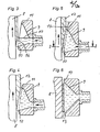
Beim Ausführungsbeispiel der Figur 1 und 2 ist oberhalb eines als Band ausgebildeten, in horizontaler Richtung bewegten Kühlkörpers 1 eine Schlitzdüse 2 angeordnet, der aus einem nicht dargestellten Gießgefäß über eine nichtdargestellte Zuleitung schmelzflüssiges Metall zugeführt wird. Der Druck, mit dem das schmelzflüssige Metall der Schlitzdüse 2 zugeführt wird, kann über die Badspiegelhöhe im Gießgefäß oder durch ein das schmelzflüssiges Metall beaufschlagendes Druckgas bestimmt werden. Die Schlitzdüse 2 ist um einen im Bereich der bandanfangseitigen Düsenlippe 3 der Schlitzdüse 2 liegenden Drehpunkt 4 verschwenkbar, so daß unter Beibehaltung des Spaltes der kühlflächeneinlaufseitigen Düsenlippe 3 von der Kühlfläche des Kühlkörpers 1 der Spalt zwischen der Kühlfläche und der bandauslaufseitigen Düsenlippe 5 eingestellt werden kann.In the exemplary embodiment in FIGS. 1 and 2, a
Für das Angießen wird die Schlitzdüse 2 derart verschwenkt, daß die Spaltbreite im Bereich der beiden Düsenlippen 3, 5 ausreichend klein sind, um ein unkontrolliertes bzw. unerwünschtes Ausfließen des schmelzflüssigen Metalls zu verhindern. Wird nun auf die bewegte Kühlfläche des Kühlkörpers 1 schmelzflüssiges Metall aus der Schlitzdüse 2 gegossen, dann bildet sich eine keilförmige Erstarrrungsfront 6. Durch kontrolliertes Verschwenken der Schlitzdüse 2 unter Berücksichtigung der Geschwindigkeit der bewegten Kühlfläche und damit auch des gegossenen Bandes 7 wird die keilförmige Erstarrungsfront 6 im Bereich der Schlitzdüse 2 zunehmend steiler. Beim Verschwenken der Schlitzdüse ist darauf zu achten, daß der freie Spalt zwischen der bandauslaufseitigen Düsenlippe 5 und der Erstarrungsfront einen oberen Grenzwert nicht überschreitet, weil sonst der sich hier aufgrund der Viskosität des schmelzflüssigen Metalls bildende und diesen freien Spalt abdichtende Meniskus nicht ausreicht, das schmelzflüssige Metall zurückzuhalten.For casting, the
Auf diese Art und Weise ist es möglich, unter Beachtung des Erstarrungsgesetzes Bänder praktisch beliebiger Breite und einer Dicke bis in den Milimeterbereich mit engen Dickentoleranzen durch Gießen herzustellen.In this way it is possible to produce strips of practically any width and thickness down to the millimeter range with narrow thickness tolerances by casting, taking into account the solidification law.
Beim Ausführungsbeispiel der Figuren 3 bis 6 bewegt sich die Kühlfläche eines Kühlkörpers 8 in vertikaler Richtung von unten nach oben. Eine schlitzförmige Düse 9, die ebenfalls von einem nicht dargestellten Vorratsbehälter mit schmelzflüssigem Metall gespeist wird, ist gegenüber der bewegten Kühlfläche des Kühlkörpers 8 so angeordnet, daß die untere Düsenlippe 10 von der Kühlfläche des Kühlkörpers einen ausreichend kleinen Abstand hat, um unter Ausnutzung 'der Viskosität des schmelzflüssigen Metalls ein unerwünschtes Ausfließen auszuschließen. Die bandauslaufseitige Düsenlippe 11 hat von der Kühlfläche des Kühlkörpers 8 einen Abstand, der der gewünschten Dicke des zu gießenden Bandes 12 entspricht.In the embodiment of Figures 3 to 6, the cooling surface of a
Beim Ausführungsbeispiel der Figuren 5 und 6 sind im Vergleich zum Ausführungsbeispiel der Figuren 3 und 4 an den seitlichen Düsenlippen schürzenartige Ansätze 13, 14 vorgesehen, die beim Angießen als Spritzschutz dienen.In the exemplary embodiment of FIGS. 5 and 6, in comparison to the exemplary embodiment of FIGS. 3 and 4, apron-
Bei den Ausführungsbeispielen der Figuren 3 bis 6 wird bei von unten nach oben bewegter Kühlfläche des Kühl- körpers 8 der Badspiegel 15 des schmelzflüssigen Metalls in dem Maße angehoben, wie die keilförmige Erstarrungsfront 16 wächst. Dabei wird darauf geachtet, daß der Spalt zwischen den seitlichen Düsenlippen und der keilförmigen Erstarrungsfront 16 des Bandes 8 bis zum Erreichen der bandauslaufseitigen Düsenlippe 11 unterhalb einer oberen Toleranzgrenze bleibt, bei der gewährleistet ist, daß kein schmelzflüssiges Metall seitlich ausfließt.In the exemplary embodiments in FIGS. 3 to 6, when the
Während mit der Düse des Ausführungsbeispiels der Figuren 1 und 2 das Gießverfahren praktisch lageunabhängig durchgeführt werden kann, ist das Gießverfahren mit Düsen nach den Ausführungsbeispielen 3 bis 6 an eine gegenüber der horizontalen geneigten Bewegungsrichtung der Kühlfläche gebunden, bei der das gegossene Band entgegen der Schwerkraft mehr oder weniger steil bergauf gerichtet die Düse verläßt.While with the nozzle of the exemplary embodiment in FIGS. 1 and 2, the casting process can be carried out practically independently of the position, the casting process with nozzles according to
Nach dem Angießen wird die Geschwindigkeit der bewegten Kühlfläche so gewählt, daß es auch dann nicht zu einem unkontrollierten Ausfließen des schmelzflüssigen Metalls kommt. Deshalb wird die Geschwindigkeit so gewählt, daß die keilförmige Erstarrungsfront innerhalb der Düse liegt.After casting, the speed of the moving cooling surface is selected so that there is no uncontrolled outflow of the molten metal. The speed is therefore selected so that the wedge-shaped solidification front lies within the nozzle.
Die Schlitzdüse nach dem Ausführungsbeispiel der Figuren 7 und 8 unterscheidet sich von dem der Figuren 1 und 2 im wesentlichen nur dadurch, daß die bandauslaufseitige Düsenlippe 17 an Federelementen 18, 19 derart abgestützt ist, daß sie bei einem einen Grenzwert des auf sie vom gegossenen Band ausgeübten Druckes ausweicht. Die Düsenlippe 17 kann durch in der Zeichnung nicht dargestellte Einstellschrauben oder Stellkeile einstellbar gestaltet sein, so daß es möglich ist, die Banddicke einzustellen. Die Düse gemäß dem Ausführungsbeispiel der Figuren 9 und 10 unterscheidet - sich von dem Ausführungsbeispiel der Figuren 1 und 2 nur darin, daß zwei Schlitzdüsen 19, 20 dicht hintereinander und parallel zueinander in einer schwenkbaren Einheit ausgebildet sind. Das aus den beiden Schlitzdüsen 19, 20 austretende schmelzflüssige Metall wird in der schmelzflüssigen Phase am Ende der Erstarrungsfront im Bereich der ersten Schlitzdüse 19 zusammengeführt, so daß es mit einer solchen Düse möglich ist, zweilagiges Bandmaterial herzustellen, daß in der Grenzzone der beiden Lagen innig miteinander verbunden ist.The slot nozzle according to the exemplary embodiment of FIGS. 7 and 8 differs from that of FIGS. 1 and 2 essentially only in that the strip lip-
Das Ausführungsbeispiel der Figuren 11 und 12 unterscheidet sich von dem der Figuren 1 und 2 darin, daß zwei Schlitzdüsen 21, 22 eng nebeneinander angeordnet und in einer verschwenkbaren Einheit ausgebildet sind. Das schmelzflüssige Metall wird im Bereich der gemeinsamen mittleren Düsenlippe in der schmelzflüssigen Phase zusammengeführt. Mit diesem Ausführungsbeispiel ist es möglich, ein aus zwei nebeneinanderliegenden Streifen bestehendes Band herzustellen, dessen beide Streifen an ihren benachbarten Rändern innig miteinander verbunden sind.The exemplary embodiment of FIGS. 11 and 12 differs from that of FIGS. 1 and 2 in that two
Das Ausführungsbeispiel der Figur 13 unterscheidet sich von dem der Figuren 1 und 2 darin, daß der Düsenschlitz durch zwei quer zur Bewegungsrichtung der Kühlfläche verlaufende Stege 23, 24 in drei Einzelschlitze 25, 26, 27 unterteilt ist. Während sich im Bereich der Teilschlitze 25, 26, 27 eine keilförmige Erstarrungsfront ausbildet, findet in den Bereichen der Stege 23, 24 eine weitere Abkühlung der hier bereits ganz erstarrten Lagen statt. Im Bereich der Stege 23, 24 werden die Lagen über Kanäle 28, 29 mit Schutzgas beaufschlagt. Die Länge der Kühlstrecken a1, a2 sollte das 0,8 bis 16fache der Weite b1, b2 des jeweils vorgelagerten Düsenschlitzes 25, 26 betragen.The exemplary embodiment in FIG. 13 differs from that in FIGS. 1 and 2 in that the nozzle slot is divided into three
Mit einer derart ausgebildeten Mehrfachdüse lassen sich dicke, amorph erstarrte Metallbänder aus einzelnen, verhältnismäßig dünnen Lagen aufbauen.With a multiple nozzle designed in this way, thick, amorphously solidified metal strips can be built up from individual, relatively thin layers.
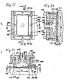
Beim Ausführungsbeispiel der Figuren 15 und 16 besteht das Besondere darin, daß ein Gießspalt, in den von unten aus einer Düse 30 schmelzflüssiges Metall eingeführt wird, von zwei Kühlrädern 31, 32 gebildet wird, die in einer horizontalen Ebene parallel nebeneinander angeordnet sind und im Bereich des Gießspaltes gleichsinnig umlaufen. Der gegenseitige Abstand der Kühlräder 31, 32 und damit die lichte Weite des Gießspaltes sind einstellbar.The special feature of the exemplary embodiment in FIGS. 15 and 16 is that a casting gap, into which molten metal is introduced from below from a
Dieses Ausführungsbeispiel wirkt wie zwei unmittelbar nebeneinander angeordnete Schlitzdüsen, bei denen unter Verzicht auf eine körperliche bandauslaufseitige Düsenlippe die beiden Erstarrungsfronten der beiden auf den Kühlrädern 31, 32 gegossenen Lagen des Bandes die Funktion der bandauslaufseitigen Düsenlippe übernehmen. Um beim Angießen ein seitliches Ausfließen des schmelzflüssigen Metalls zu verhindern, wird unter Beachtung der sich in Abhängigkeit von der Geschwindigkeit der Kühlflächen der Kühlräder 31, 32 aufbauenden Erstarrungsfronten die Weite des Gießspaltes von einem kleinen Anfangswert auf den Endwert vergrößert, der der gewünschten Banddicke entspricht, so daß es nicht zu einem unerwünschten Ausfließen von schmelzflüssigem Metall kommt. Dieses Ausführungsbeispiel basiert auf dem Prinzip des Ausführungsbeispiels der Figuren 1 und 2.This exemplary embodiment acts like two slot nozzles arranged directly next to one another, in which the two solidification fronts of the two layers of the strip cast on the cooling
Das Ausführungsbeispiel der Figuren 16 und 17 unterscheidet sich von dem der Figuren 14 und 15 dadurch, daß der Gießspalt nicht aus einer Düse sondern aus zwei Düsen 33, 34 gespeist wird. Mit diesem Ausführungsbeispiel lassen sich zweilagige Bänder aus verschiedenen Metallen, also Bimetallbänder herstellen. Wie beim Ausführungsbeispiel der Figuren 9 und 10 werden auch in diesem Fall die Metalle der beiden Lagen in der schmelzflüssigen Phase zusammengeführt. Ähnlich dem Ausführungsbeispiel der .Figuren 5 und 6 kann an den Seiten ein schürzenartiger Spritzschutz 35 vorgesehen sein. Ein solcher Spritzschutz kann selbstverständlich auch beim Ausführungsbeispiel der Figuren 14 und 15 vorgesehen sein.The exemplary embodiment of FIGS. 16 and 17 differs from that of FIGS. 14 and 15 in that the casting gap is fed not from one nozzle but from two
Bei den Ausführungsbeispielen der Figuren 18 bis 21 ist die bandauslaufseitige Düsenlippe 36, 37 profiliert. Die Düsenlippe 36, 37 hat also über die Breite der Düse einen unterschiedlichen Abstand zur Kühlfläche. Damit sich unter Berücksichtigung-dieses Profils eine Erstarrungsfront ausbilden kann, die ein unkontrolliertes Ausfließen schmelzflüssigen Metalls verhindert, ist die jeweilige Düsen- weite in Bewegungsrichtung der Kühlfläche gesehen in Abhängigkeit von der jeweiligen Banddicke gestaltet, d.h., daß bei kleiner Banddicke und damit auch geringem Abstand der Düsenlippe von der Kühlfläche die Düsenweite klein ist und bei großer Banddicke und damit auch großem Abstand der Düsenlippe von der Kühlfläche die Düsenweite groß ist. In Figur 20 links ist das Profil der Düsenlippe in Drauf- sicht dargestellt.In the exemplary embodiments in FIGS. 18 to 21, the
Nach diesem Prinzip lassen sich sehr unterschiedlich profilierte und Stränge gießen, wobei immer gewährleistet ist, daß es nicht zu einem unerwünschten Ausfließen von schmelzflüssigem Metall kommt und die Profile sehr maßgenau sind.According to this principle, very different profiled and strands can be cast, whereby it is always ensured that there is no undesired outflow of molten metal and that the profiles are very dimensionally accurate.
Mit den Ausführungsbeispielen der Figuren 22 bis 33 lassen sich während des Gießbetriebes noch engere Toleranzen und glattere Oberflächen des Bandes erzielen.With the exemplary embodiments of FIGS. 22 to 33, even tighter tolerances and smoother surfaces of the strip can be achieved during the casting operation.
Die in den Figuren 22 bis 24 dargestellte Schlitzdüse 101 weist einen Düsenkörper 102 auf, der in einem Halter 103 sitzt. Die Düsenkammer 104 der Schlitzdüse 101 ist über eine Leitung 105 mit einem nicht dargestellten Gefäß für schmelzflüssiges Metall verbunden. Das schmelzflüssige Metall läßt sich mit Druck in die Kammer 104 einbringen. Mittels Stellgliedern 106 läßt sich die Schlitzdüse 101 bezüglich der Neigung und des Abstandes ihrer Stirnseite gegenüber der Kühlfläche 107 eines sonst nicht weiter dargestellten, in Richtung des Pfeils 108 bewegbaren Kühlkörpers einstellen.The slot nozzle 101 shown in FIGS. 22 to 24 has a
Wie aus Fig.24 ersichtlich, entwickelt sich bei in Richtung des Pfeils 108 mit der Geschwindigkeit v vorbewegter Kühlfläche 107 auf der Kühlfläche 107 im Bereich der Düsenkammer 104 ein Erstarrungskeil 109, der am bandauslaufseitigen Rand der Kammer 104 die Dicke d des fertigen Bandes 110 erreicht. Die Erstarrung ist also im Bereich der Düsenkammer 104 abgeschlossen.As can be seen from FIG. 24, with cooling
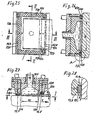
In den Stirnseiten der kühlflächeneinlaufseitigen, bandauslaufseitigen und seitlichen Düsenlippen 111 bis 114 ist jeweils eine flache Kammer 115 bis 118 vorgesehen, der über jeweils eine Leitung 119 bis 122 für den Aufbau eines stirnseitigen Gaskissens 123,124,125,126 Gas zuführbar ist, mit dem sich die Schlitzdüse auf der Kühlfläche 107 und der Oberseite des fertigen Bandes 110 abstützt. Über den Gasdruck in den einzelnen Gaskissen 123 bis 126 ist der Abstand der Düsenlippen 111 bis 114 von der Kühlfläche 107 und dem Band 110 einstellbar.A
Das Ausführungsbeispiel der Figuren 25 bis 28 unterscheidet sich von dem der Figuren 22 bis 24 in zwei Merkmalen. Die Zufuhr von Druckgas und die Verteilung von Druckgas erfolgt über leistenartige poröse Körper 127 bis 130, deren der Düsenkammer 135 zugekehrte Seiten einen gasdichten Überzug 129a tragen, so daß das zugeführte Gas vor der porösen Stirnseite eines jeden porösen Körpers 128 bis 130 sich aufbauen und, wie in Fig.28 angedeutet, abströmen kann. Die porösen Körper 127,129,130 sind in keilförmigen Nuten 131 bis 133 fixiert, während der bandauslaufseitige poröse Körper 128 in einer Nut 134 mit parallelen Wänden verstellbar in Richtung auf die Kühlfläche 107 gehalten ist. Auf diese Art und Weise kann sich das Luftkissen mit dem porösen Körper 128 schwankenden Dicken des Bandes anpassen und die Abstützung gewährleisten.The exemplary embodiment of FIGS. 25 to 28 differs from that of FIGS. 22 to 24 in two features. The supply of pressurized gas and the distribution of pressurized gas takes place via strip-like
Das zweite von dem Ausführungsbeispiel der Fig.22 bis 24 abweichende Merkmal besteht darin, daß zwischen den die porösen Körper 127 bis 130 enthaltenden Luftkissen und der Düsenkammer 135 Kammern 136,137 angeordnet sind, in die entweder erhitztes Schutzgas über Leitungen 138,139 einführbar ist oder über die aus den Luftkissen austretendes Gas abführbar ist. Durch beide Alternativen soll verhindert werden, daß die Bandoberfläche oxydiert. Vor allem durch die Zufuhr von Schutzgas oder durch die Abfuhr von Gas aus dem Luftkissen über die kühlflächeneinlaufseitige Kammer 136 soll zusätzlich verhindert werden, daß sich zwischen der Kühlfläche 107 und der zugewandten Bandseite Kondensat- und Gasperlen in einem Ausmaß entwickeln, daß die Glätte der Bandoberfläche beeinträchtigt wird.The second feature which differs from the exemplary embodiment in FIGS. 22 to 24 is that between the air cushions containing the
Da die Kühlfläche 107 in der Regel breiter als das gegossene Band 110 ist, wird von den Bandrändern die Wärme besser als von der Bandmitte abgeführt. Deshalb ist die keilförmige Erstarrungsfront im Bereich der Düsenkammer an den Bandrändern steiler als im mittleren Bandbereich. Dieser Tatsache trägt das Ausführungsbeispiel der Figuren 29 bis 31 Rechnung. Während im Bereich W1 die Erstarrung an den Bandrändern abgeschlossen ist, erstreckt sie sich in der Bandmitte über den Bereich W. Durch den im Vergleich zu den anderen Ausführungsbeispielen größeren Abstand des bandauslaufseitigen, einen porösen Körper 140 enthaltenden Luftkissens ist es möglich, daß zwischen den erstarrten Randbereichen 141,142 des Bandes 143 schmelzflüssiges Metall den auslaufseitigen Rand 145 der Düsenkammer 146 passiert und in dem Abschnitt zwischen diesem Rand 145 und dem porösen Körper 140 erstarrt. Wegen des in diesem Bereich aufgebauten Druckes kann schmelzflüssiges Metall nicht unkontrolliert durch den im mittleren Bereich größeren Spalt austreten.Since the
Das Ausführungsbeispiel der Figuren 29 bis 31 unterscheidet sich von den vorhergehenden dadurch, daß der bandauslaufseitige Rand 145 von einer auswechselbaren durch eine Heizeinrichtung 146 beheizte Leiste 147 gebildet wird. Durch diese beheizte Leiste wird ein Einfrieren des Metalls an der Bandoberseite bereits im Bereich des Randes 145 verhindert und deshalb eine glatte Bandoberfläche erzielt. Ferner unterscheidet sich dieses Ausführungsbeispiel von den vorhergehenden noch dadurch, daß die porösen Körper 140 an der einlaufseitigen Düsenlippe und der auslaufseitigen Düsenlippe zumindest einen teilweise runden Querschnitt und eine ebene Stirnfläche haben und in den entsprechend ausgebildeten Nuten um ihre Achsen verdrehbar sind. Dadurch wird erreicht, daß die flachen Stirnseiten der porösen Körper 140 bei jedem Neigungswinkel der Stirnseite der Düse sich zur Kühlfläche und Bandoberfläche parallel stellen. Schließlich besteht ein weiterer Unterschied darin, daß die seitlichen porösen Körper 148 in Nuten 149 höhenverstellbar gelagert sind, um sich in Abhängigkeit von dem Neigungswinkel der Stirnseite der Düse selbständig einzustellen.The exemplary embodiment in FIGS. 29 to 31 differs from the previous ones in that the
Bei dem Ausführungsbeispiel der Figuren 32 und 33 sind die teilweise einen Kreisquerschnitt und eine flache Stirnseite aufweisenden porösen Körper 150 bis 153 in einstellbaren Haltern 154 bis 157 angeordnet, so daß es möglich ist, die Schlitzdüse in ihrer Lage gegenüber der Kühlfläche und davon unabhängig die Halter 154 bis 157 mit den porösen Körpern 150 bis 153 einzustellen. Darüber hinaus sind in dem Düsenkörper auswechselbare Düsenlippen 158,159 eingesetzt, die über Kanäle 160,161 beheizbar sind.In the exemplary embodiment in FIGS. 32 and 33, the
Die gasdurchlässigen porösen Körper 127 bis 130, 140, 150 bis 153 bestehen vorzugsweise aus Sintermaterial, Keramikfaser, Kohlegraphit oder einem ähnlichen Werkstoff nach Möglichkeit mit gewissen Notlaufeigenschaften gegenüber dem Werkstoff der Kühlfläche.The gas-permeable
Als Werkstoff für die einsetzbaren, beheizbaren Düsenlippen 145,158,159 eignet sich hochhitzebeständiges Metall, wie Wolfram, Molybden oder eine entsprechende Metallegierung oder ein verschleißfester, hitzeschockbeständiger, möglichst schmelzeabweisender Keramikwerkstoff, wie A1203, SiC, Si3N4, ZrO2, Ng0 oder dergl. Statt eingesetzter Düsenlippen kann der Düsenkörper aber auch an der Stirnseite mit solchen Materialen aufgepanzert oder aufgesintert sein. Vorzugsweise sind die Düsenlippen beheizt.As a material for the usable,
Claims (37)
dadurch gekennzeichnet, daß unter Berücksichtigung der sich beim Angießen auf die bewegte Kühlfläche des Kühlkörpers im Bereich der Düse keilförmig aufbauenden Erstarrungsfront und unter Anpassung der Geschwindigkeit der Kühlfläche der freie Spalt zwischen der strangauslaufseitigen Düsenlippe und gegebenenfalls den seitlichen Düsenlippen von einem ein unkontrolliertes Ausfließen des schmelzflüssigen Metalls verhindernden kleinen Anfangswert allmählich auf den der gewünschten Strangdicke entsprechenden, ebenfalls ein unkontrolliertes Ausfließen verhindernden Endwert vergrößert wird.1. A process for producing metal strands in the form of strips or profiles, in which molten metal is applied from a nozzle, in particular a slit nozzle, to the cooling surface of a heat sink that is moved past the nozzle with a narrow gap.
characterized in that, taking into account the solidification front which builds up in a wedge shape in the area of the nozzle when casting onto the moving cooling surface of the heat sink and adapting the speed of the cooling surface, the free gap between the nozzle lip on the strand outlet side and optionally the lateral nozzle lips from an uncontrolled outflow of the molten metal preventing small initial value is gradually increased to the final value corresponding to the desired strand thickness, which also prevents uncontrolled outflow.
dadurch gekennzeichnet, daß unter - Berücksichtigung der sich beim Angießen auf den von unten nach oben bewegten Kühlflächenteil des Kühlkörpers im Bereich der Düsenlippe keilförmig aufbauenden Erstarrungsfront der Schmelzbadspiegel zwischen der Kühlfläche des Kühlkörpers und der seitlich neben dem Kühlkörper angeordneten Düse allmählich bis zur die Strangdicke bestimmenden auslaufseitigen Düsenlippe derart angehoben wird, daß, wenn der Schmelzbadspiegel die auslaufseitige Düsenlippe erreicht, der freie Spalt zwischen der Erstarrungsfront und der auslaufseitigen Düsenlippe ausreichend klein ist, um ein unkontrolliertes Ausfließen des schmelzflüssigen Metalls zu verhindern.2. A process for producing metal strands in the form of strips or profiles, in which molten metal is applied from a nozzle, in particular a slit nozzle, to the cooling surface of a heat sink that is moved past the nozzle with a narrow gap.
characterized in that taking into account the cooling surface part of the heat sink moving when pouring onto the cooling surface part moving from bottom to top The area of the nozzle lip of the solidification front of the melt pool, which builds up in a wedge shape, is gradually raised between the cooling surface of the heat sink and the nozzle arranged on the side next to the heat sink up to the outlet-side nozzle lip that determines the strand thickness, such that when the melt pool reaches the nozzle lip on the outlet side, the free gap between the solidification front and the nozzle lip on the outlet side is sufficiently small to prevent the molten metal from flowing out in an uncontrolled manner.
dadurch gekennzeichnet , daß das Anheben des Schmelzbadspiegels derart erfolgt, daß der freie Spalt zwischen den seitlichen Düsenlippen und der Erstarrungsfront ausreichend klein bleibt, um ein unkontrolliertes Ausfließen des schmelzflüssigen Metalls zu verhindern.3. The method according to claim 2,
characterized in that the raising of the melt pool level takes place in such a way that the free gap between the lateral nozzle lips and the solidification front remains sufficiently small to prevent the molten metal from flowing out in an uncontrolled manner.
dadurch gekennzeichnet, daß nach dem Angießen die Geschwindigkeit der Kühlfläche des Kühlkörpers derart eingestellt wird, daß die Erstarrungsfront innerhalb der Düse bleibt.4. The method according to any one of claims 1 to 3,
characterized in that after the casting, the speed of the cooling surface of the heat sink is adjusted such that the solidification front remains within the nozzle.
dadurch gekennzeiehnet, daß auf die kühlflächenabgewandte Oberfläche des gegossenen Metallbandes aus einer in Bewegungsrichtung der Kühlfläche unmittelbar vor der einen Düse angeordneten weiteren Düse in der gleichen Art wie aus der einen Düse schmelzflüssiges Metall aufgebracht wird.5. The method according to any one of claims 1 to 4,
characterized in that molten metal is applied to the surface of the cast metal strip facing away from the cooling surface from a further nozzle arranged directly in front of the one nozzle in the direction of movement of the cooling surface in the same way as from the one nozzle.
dadurch gekennzeiehnet, daß das sehmelzflüssige Metall aus der weiteren Düse auf das an der Oberfläche noch schmelzflüssige Metallband aus der einen Düse aufgebracht wird.6. The method according to claim 5,
characterized gekennzeiehnet that the molten metal from the further nozzle on the at the Surface still molten metal tape from which a nozzle is applied.
dadurch gekennzeichnet , daß die kühlflächenabgewandte Oberfläche des einen Metallbandes vor oxydierenden Einflüssen bis zum Aufbringen des weiteren schmelzflüssigen Metalls geschützt wird.7. The method according to claim 5 or 6,
characterized in that the surface of a metal strip facing away from the cooling surface is protected from oxidizing influences until the further molten metal is applied.
dadurch gekennzeichnet, daß auf die bewegte Kühlfläche unmittelbar neben dem schmelzflüssigen Metall aus der einen Düse schmelzflüssiges Metall aus einer oder mehreren weiteren Düsen in der gleichen Art wie aus der einen Düse aufgebracht wird, daß die aus den beiden Düsen austretenden Metalle in ihrer schmelzflüssigen Phase im Bereich ihrer Grenzzonen zusammengeführt werden.8. The method according to any one of claims 1 to 4,
characterized in that molten metal from one or more further nozzles is applied to the moving cooling surface directly next to the molten metal from one nozzle in the same manner as from one nozzle, that the metals emerging from the two nozzles in their molten phase in Area of their border zones.
dadurch gekennzeiehnet, daß verschiedene Metalle zusammengeführt werden.9. The method according to any one of claims 5 to 7,
characterized in that different metals are brought together.
dadurch gekennzeiehnet, daß beim Übereinandergießen von mehreren Lagen nach dem Gießen einer jeden Lage das Band eine Kühlstrecke durchläuft, bevor die nächste Lage aufgegossen wird.10. The method according to any one of claims 5 to 7,
characterized in that when several layers are poured on top of each other after the casting of each layer, the strip passes through a cooling section before the next layer is poured on.
dadurch gekennzeichnet, daß im Bereich jeder Kühlstrecke die kühlflächenabgewandte Oberfläche der jeweiligen Lage unter einer Schutzgasatmosphäre gehalten wird oder dieser Bereich zumindest teilevakuiert wird.11. The method according to claim 10,
characterized in that in the area of each cooling section the surface of the respective layer facing away from the cooling surface is kept under a protective gas atmosphere or this area is at least partially evacuated.
dadurch gekennzeichnet , daß die Länge der Kühlstrecke das 0,8 bis 16fache der Weite der vorgeordneten Düse in Bewegungsrichtung der Kühlfläche des Kühlkörpers beträgt.12. The method according to claim 10 or 11,
characterized in that the length of the cooling section is 0.8 to 16 times the width of the upstream nozzle in the direction of movement of the cooling surface of the heat sink.
dadurch gekennzeichnet, daß unter Verzicht auf die auslaufseitige Düsenlippe das schmelzflüssige Metall zwischen die bewegten Kühlflächen von zwei entsprechend der sich aufbauenden Erstarrungsfronten im gegenseitigen Abstand einstellbaren Kühlkörpern gegossen wird, wobei die Funktion der fehlenden Düsenlippe für das auf jeder Kühlfläche gegossene schmelzflüssige Metall von der Erstarrungsfront des jeweils anderen Stranges ausgeübt wird.13. The method according to any one of claims 1 to 4,
characterized in that, without the nozzle lip on the outlet side, the molten metal is poured between the moving cooling surfaces by two heat sinks which can be set at a mutual distance according to the solidification fronts which build up, the function of the missing nozzle lip for the molten metal poured on each cooling surface from the solidification front of the each other is exercised.
dadurch gekennzeichnet , daß auf die beiden Kühlflächen aus parallel zueinander angeordneten Schlitzdüsen verschiedene Metalle aufgebracht und in ihrer schmelzflüssigen Phase mit ihren Erstarrungsfronten zusammengeführt werden.14. The method according to claim 13,
characterized in that different metals are applied to the two cooling surfaces from slot nozzles arranged parallel to one another and are brought together in their molten phase with their solidification fronts.
dadurch gekennzeichnet, daß die auslaufseitige Düsenlippe (5) in ihrem Abstand von der Kühlfläche des Kühlkörpers (1) einstellbar ist.15. An apparatus for performing the method for casting metal strands in the form of strips and profiles according to claim 1, consisting of a nozzle designed in particular as a slot nozzle, which is connected to a reservoir for molten metal, and a heat sink, on the front with a narrow gap and in particular, the molten metal can be applied at an angle to the end face of the nozzle and movable relative to it,
characterized in that the outlet-side nozzle lip (5) is adjustable in its distance from the cooling surface of the heat sink (1).
dadurch gekennzeiehnet, daß die Düse (2) um eine parallel zur Kühlfläche des Kühlkörpers (1) und quer zu deren Bewegungsrichtung verlaufende Achse (3) schwenkbar ist.16. The apparatus of claim 15,
characterized in that the nozzle (2) can be pivoted about an axis (3) running parallel to the cooling surface of the heat sink (1) and transversely to the direction of movement thereof.
dadurch gekennzeichnet, daß die Kühlfläche des Kühlkörpers (8) im Bereich der Düse (9) gegenüber der Horizontalen geneigt angeordnet ist, wobei die Weite der Düse (lichter Abstand) der kühlflächenein-und strangauslaufseitigen Düsenlippe (10,11) in einem der Länge der keilförmigen Erstarrungsfront des zu gießenden Stranges (12) entsprechenden Abstand angeordnet ist.17. An apparatus for performing the method for casting metal strands in the form of strips or profiles according to claim 2 or 3, consisting of a nozzle designed in particular as a slot nozzle, which is connected to a reservoir for molten metal, and a heat sink, on the narrow Gap in front of and in particular inclined to the end face of the nozzle and movable relative to the cooling surface, the molten metal can be applied,
characterized in that the cooling surface of the heat sink (8) in the region of the nozzle (9) is arranged inclined with respect to the horizontal, the width of the nozzle (clear distance) of the cooling surface inlet and strand outlet-side nozzle lip (10, 11) in one of the lengths of the wedge-shaped solidification front of the strand to be cast (12) is arranged at a corresponding distance.
dadurch gekennzeichnet, daß neben dem einen Kühlkörper (31) ein zweiter Kühlkörper (32) mit gleichsinnig bewegbarer Kühlfläche abstandsveränderbar angeordnet ist, dessen Kühlfläche mit der Kühlfläche des einen Kühlkörpers (31) die Schlitzdüse (Gießspalt) bildet, der von unten das schmelzflüssige Metall zuführbar ist.18. Apparatus for carrying out the method for casting strips according to claim 13, consisting of a nozzle designed as a slot nozzle which can be supplied with molten metal from a storage container, and a movable heat sink, on the cooling surface of which the molten metal can be applied,
characterized in that, in addition to the one heat sink (31), a second heat sink (32) with a cooling surface which can be moved in the same direction is arranged, the cooling surface of which, together with the cooling surface of the one heat sink (31), forms the slot nozzle (casting gap), from which the molten metal can be fed from below is.
dadurch gekennzeichnet , daß die Kühlkörper (31,32) als Rollen ausgebildet sind.19. The apparatus according to claim 18,
characterized in that the heat sinks (31, 32) are designed as rollers.
dadurch gekennzeichnet , daß in die Schlitzdüse (Gießspalt) schmelzflüssiges Metall aus zwei parallel zueinander angeordneten Düsenschlitzen (33,34) speisbar ist.20. The apparatus according to claim 18,
characterized in that molten metal can be fed into the slot nozzle (pouring gap) from two nozzle slots (33, 34) arranged parallel to one another.
dadurch gekennzeichnet , daß die Düse (9,33,34) an ihren seitlichen Düsenlippen vorstehende Ansätze (13,14,35) als Spritzschutz aufweist.21. Device according to one of claims 15 to 20,
characterized in that the nozzle (9, 33, 34) has projections (13, 14, 35) on its lateral nozzle lips as splash protection.
dadurch gekennzeichnet , daß die strangauslaufseitige Düsenlippe (17) gegenüber Druck ausweichbar gelagert ist.22. The device according to one of claims 15 to 17,
characterized in that the nozzle lip (17) on the strand outlet side is mounted so as to be able to withstand pressure.
dadurch gekennzeichnet , daß in Bewegungsrichtung der Kühlfläche zwei oder mehr Düsen (19,20,25,26,27; 21,22) eng hinter- oder nebeneinander angeordnet sind.23. The device according to one of claims 15 to 17,
characterized in that two or more nozzles (19, 20, 25, 26, 27; 21, 22) are arranged closely behind or next to one another in the direction of movement of the cooling surface.
dadurch gekennzeichnet , daß in einer Schlitzdüse zwei oder mehr Düsenschlitze (25,26,27) in Bewegungsrichtung der Kühlfläche hintereinander und parallel zueinander angeordnet sind, wobei der Abstand zwischen zwei benachbarten Düsenschlitzen das 0,8 bis 16fache der Weite des jeweils vorgelagerten Düsenschlitzes beträgt.24. The device according to one of claims 15 to 19,
characterized in that two or more nozzle slots (25, 26, 27) are arranged one behind the other and parallel to one another in the direction of movement of the cooling surface in a slot nozzle, the distance between two adjacent nozzle slots being 0.8 to 16 times the width of the respective upstream nozzle slot.
gekennzeichnet , daß zwischen den Düsenschlitzen (25,26,27) Zwischenräume oberhalb des Bandes vorgesehen sind, die teilevakuierbar oder mit einem Schutzgas beaufschlagbar sind.25. The device according to claim 24, characterized
characterized in that there are spaces between the nozzle slots (25, 26, 27) above the belt which can be partially evacuated or can be supplied with a protective gas.
dadurch gekennzeichnet , daß die strangauslaufseitige Düsenlippe (36,37) derart profiliert ist, daß sie zur Kühlfläche des Kühlkörpers (38,39) einen über die Strangbreite unterschiedlich weiten Spalt bildet, und die kühlflächeneinlaufseitige Düsenlippe (40,41) entsprechend dem Profil der strangauslaufseitigen Düsenlippe (36,37) in Bewegungsrichtung der Kühlfläche des Kühlkörpers (38,39) derart versetzt ist, daß im Bereich eines großen Spaltes die kühlflächeneinlaufseitige Düsenlippe (40,41) von der strangauslaufseitigen Düsenlippe (36,37) einen größeren Abstand als im Bereich eines kleinen Spaltes hat.26. The device according to one of claims 15 to 17,
characterized in that the extrusion-side nozzle lip (36,37) is profiled in such a way that it forms a gap that is different in width over the strand width to the cooling surface of the heat sink (38,39), and the cooling-surface inlet-side nozzle lip (40,41) in accordance with the profile of the extrusion-side Nozzle lip (36, 37) is displaced in the direction of movement of the cooling surface of the heat sink (38, 39) in such a way that, in the area of a large gap, the nozzle lip (40, 41) on the cooling surface inlet side is a greater distance from the extrusion-side nozzle lip (36, 37) than in the area of a small gap.
dadurch gekennzeichnet , daß die Schlitzdüse (101) mit ihrem stirnseitigen Rand (111 bis 114) über ein oder mehrere Gaskissen (123 bis 126) auf der Kühlfläche (107) und der freien Oberfläche des gegossenen Metallbandes (110) abstützbar ist.28. Device for casting metal strands, in particular metal strips, consisting of a slot nozzle, which is connected to a reservoir for molten metal, and a heat sink, on the cooling surface of which is arranged with a narrow gap in front of and inclined to the end face of the slot nozzle and movable relative to it the molten metal can be applied, in particular according to claim 15 or 17,
characterized in that the slot nozzle (101) with its front edge (111 to 114) over one or more gas cushions (123 to 126) on the Cooling surface (107) and the free surface of the cast metal strip (110) can be supported.
dadurch gekennzeichnet , daß das oder die Gaskissen (123 bis 126) einen geschlossenen Ring bilden.29. The device according to claim 28,
characterized in that the gas cushion (s) (123 to 126) form a closed ring.
dadurch gekennzeichnet , daß der Gasdruck in den Gaskissen (123 bis 126) einstellbar ist.30. The device according to claim 28 or 29,
characterized in that the gas pressure in the gas cushion (123 to 126) is adjustable.
dadurch gekennzeichnet , daß zwischen dem oder den Gaskissen (127 bis 130) und zumindest der kühlflächeneinlaufseitigen Düsenlippe eine Kammer (136,137) vorgesehen ist, die teilevakuiert ist oder über die erhitztes Gas zuführbar ist.31. Device according to one of claims 28 to 30,
characterized in that a chamber (136, 137) is provided between the gas cushion (s) (127 to 130) and at least the cooling lip inlet side, which is partially evacuated or via which heated gas can be supplied.
dadurch gekennzeichnet, daß entsprechende Kammern vor den seitlichen Düsenlippen angeordnet sind.32. Device according to claim 31,
characterized in that corresponding chambers are arranged in front of the lateral nozzle lips.
dadurch gekennzeichnet , daß eine entsprechende Kammer (137) vor der strangauslaufseitigen Düsenlippe angeordnet ist.33. Device according to claim 31 or 32,
characterized in that a corresponding chamber (137) is arranged in front of the nozzle lip on the strand outlet side.
dadurch gekennzeichnet , daß zumindest das kühlflächeneinlaufseitige Gaskissen (123) mit erhitztem Gas beaufschlagbar ist.34. Device according to one of claims 1 to 6,
characterized in that at least the gas cushion (123) on the cooling surface inlet side can be acted upon by heated gas.
dadurch gekennzeichnet , daß das oder die Gaskissen (127 bis 130) einen porösen Körper enthalten, über den das zum Druckaufbau benötigte Gas zuführbar ist.35. Device according to one of claims 28 to 34,
characterized in that the or the gas cushions (127 to 130) contain a porous body, via which the gas required for building up pressure can be supplied.
dadurch gekennzeichnet, daß der poröse Körper (128) in einer Führung (134) des Schlitzdüsenkörpers (102) derart beweglich gehalten ist, daß er sich selbständig auf die Lage der Kühlfläche und/oder der Strangoberfläche einstellt.36. Device according to claim 35,
characterized in that the porous body (128) is movably held in a guide (134) of the slot nozzle body (102) in such a way that it adjusts itself automatically to the position of the cooling surface and / or the strand surface.
Priority Applications (1)
| Application Number | Priority Date | Filing Date | Title |
|---|---|---|---|
| AT86107532T ATE70752T1 (en) | 1985-06-19 | 1986-06-03 | PROCESS FOR PRODUCTION OF A METAL STRAND, PARTICULARLY IN THE FORM OF A STRIP OR PROFILE BY CASTING AND DEVICE FOR CARRYING OUT THIS PROCESS. |
Applications Claiming Priority (4)
| Application Number | Priority Date | Filing Date | Title |
|---|---|---|---|
| DE3521778 | 1985-06-19 | ||
| DE19853521778 DE3521778A1 (en) | 1985-06-19 | 1985-06-19 | Method for the production of a metal strand, in particular in the form of a strip or section, by casting and an apparatus for carrying out this method |
| DE3602594 | 1986-01-29 | ||
| DE19863602594 DE3602594A1 (en) | 1986-01-29 | 1986-01-29 | Apparatus for casting metal strips on a moving cooling element |
Publications (3)
| Publication Number | Publication Date |
|---|---|
| EP0208890A2 true EP0208890A2 (en) | 1987-01-21 |
| EP0208890A3 EP0208890A3 (en) | 1988-10-26 |
| EP0208890B1 EP0208890B1 (en) | 1991-12-27 |
Family
ID=25833220
Family Applications (1)
| Application Number | Title | Priority Date | Filing Date |
|---|---|---|---|
| EP86107532A Expired - Lifetime EP0208890B1 (en) | 1985-06-19 | 1986-06-03 | Process for the continuous casting of a metal strand, especially as a band or profile, and device for carrying out the process |
Country Status (4)
| Country | Link |
|---|---|
| US (1) | US4719963A (en) |
| EP (1) | EP0208890B1 (en) |
| AT (1) | ATE70752T1 (en) |
| DE (1) | DE3683096D1 (en) |
Cited By (3)
| Publication number | Priority date | Publication date | Assignee | Title |
|---|---|---|---|---|
| DE3707897A1 (en) * | 1987-03-12 | 1988-09-22 | Mannesmann Ag | METHOD AND CASTING DEVICE FOR CASTING METAL STRIPS, ESPECIALLY STEEL |
| EP0502344A1 (en) * | 1991-03-06 | 1992-09-09 | Tetra Laval Holdings & Finance SA | An apparatus for producing web-shaped metal foil |
| EP2457264A4 (en) * | 2009-07-21 | 2015-03-04 | James B Sears | System and method for making a photovoltaic unit |
Families Citing this family (3)
| Publication number | Priority date | Publication date | Assignee | Title |
|---|---|---|---|---|
| US4942918A (en) * | 1988-09-26 | 1990-07-24 | Maringer Robert E | Controlled-flow fiber casting |
| JP3643089B2 (en) * | 2002-05-01 | 2005-04-27 | 三菱電機株式会社 | nozzle |
| DE102011002069A1 (en) * | 2011-04-14 | 2012-10-18 | Nordenia Deutschland Gronau Gmbh | Adhesive nozzle for applying adhesive to a moving material web |
Citations (9)
| Publication number | Priority date | Publication date | Assignee | Title |
|---|---|---|---|---|
| US2348178A (en) * | 1937-11-03 | 1944-05-02 | Joseph M Merle | Method of making metallic products of sheetlike form |
| US4290476A (en) * | 1980-01-14 | 1981-09-22 | Allied Chemical Corporation | Nozzle geometry for planar flow casting of metal ribbon |
| EP0050397A2 (en) * | 1980-10-22 | 1982-04-28 | Wilkinson Sword Limited | Cast metallic strip and method and apparatus for producing same |
| JPS59130658A (en) * | 1983-01-17 | 1984-07-27 | Hitachi Cable Ltd | Production of composite metallic rod |
| JPS59215257A (en) * | 1983-05-20 | 1984-12-05 | Ishikawajima Harima Heavy Ind Co Ltd | Casting method in twin roll type continuous casting machine |
| DE3442009A1 (en) * | 1983-11-18 | 1985-06-05 | Nippon Steel Corp., Tokio/Tokyo | AMORPHOUS ALLOY TAPE WITH LARGE THICKNESS AND METHOD FOR THE PRODUCTION THEREOF |
| JPS60199552A (en) * | 1984-03-23 | 1985-10-09 | Nippon Steel Corp | Production of thin metallic strip |
| GB2160806A (en) * | 1984-06-28 | 1986-01-02 | Mannesmann Ag | Continuous casting of molten metal |
| US4588015A (en) * | 1984-10-17 | 1986-05-13 | Allied Corporation | Casting in an exothermic reducing flame atmosphere |
Family Cites Families (8)
| Publication number | Priority date | Publication date | Assignee | Title |
|---|---|---|---|---|
| US2171132A (en) * | 1937-06-19 | 1939-08-29 | Simons Aaron | Method of forming elements from molten metal |
| US4285386A (en) * | 1979-03-16 | 1981-08-25 | Allied Chemical Corporation | Continuous casting method and apparatus for making defined shapes of thin sheet |
| DE2938709A1 (en) * | 1979-09-25 | 1981-04-02 | Vacuumschmelze Gmbh, 6450 Hanau | METHOD AND DEVICE FOR PRODUCING AMORPHOUS METAL BANDS |
| US4479528A (en) * | 1980-05-09 | 1984-10-30 | Allegheny Ludlum Steel Corporation | Strip casting apparatus |
| US4485839A (en) * | 1980-10-22 | 1984-12-04 | Allegheny Ludlum Steel Corporation | Rapidly cast alloy strip having dissimilar portions |
| JPS5816761A (en) * | 1981-07-21 | 1983-01-31 | Furukawa Electric Co Ltd:The | Production of thin metallic strip |
| EP0126267A1 (en) * | 1983-05-12 | 1984-11-28 | Allied Corporation | Casting apparatus for controlling puddle stability and nozzle degradation |
| JPS60174239A (en) * | 1984-02-20 | 1985-09-07 | Hitachi Zosen Corp | Nozzle for producing ultrathin walled tape |
-
1986
- 1986-06-03 EP EP86107532A patent/EP0208890B1/en not_active Expired - Lifetime
- 1986-06-03 DE DE8686107532T patent/DE3683096D1/en not_active Expired - Fee Related
- 1986-06-03 AT AT86107532T patent/ATE70752T1/en not_active IP Right Cessation
- 1986-06-12 US US06/873,557 patent/US4719963A/en not_active Expired - Fee Related
Patent Citations (9)
| Publication number | Priority date | Publication date | Assignee | Title |
|---|---|---|---|---|
| US2348178A (en) * | 1937-11-03 | 1944-05-02 | Joseph M Merle | Method of making metallic products of sheetlike form |
| US4290476A (en) * | 1980-01-14 | 1981-09-22 | Allied Chemical Corporation | Nozzle geometry for planar flow casting of metal ribbon |
| EP0050397A2 (en) * | 1980-10-22 | 1982-04-28 | Wilkinson Sword Limited | Cast metallic strip and method and apparatus for producing same |
| JPS59130658A (en) * | 1983-01-17 | 1984-07-27 | Hitachi Cable Ltd | Production of composite metallic rod |
| JPS59215257A (en) * | 1983-05-20 | 1984-12-05 | Ishikawajima Harima Heavy Ind Co Ltd | Casting method in twin roll type continuous casting machine |
| DE3442009A1 (en) * | 1983-11-18 | 1985-06-05 | Nippon Steel Corp., Tokio/Tokyo | AMORPHOUS ALLOY TAPE WITH LARGE THICKNESS AND METHOD FOR THE PRODUCTION THEREOF |
| JPS60199552A (en) * | 1984-03-23 | 1985-10-09 | Nippon Steel Corp | Production of thin metallic strip |
| GB2160806A (en) * | 1984-06-28 | 1986-01-02 | Mannesmann Ag | Continuous casting of molten metal |
| US4588015A (en) * | 1984-10-17 | 1986-05-13 | Allied Corporation | Casting in an exothermic reducing flame atmosphere |
Non-Patent Citations (3)
| Title |
|---|
| PATENT ABSTRACTS OF JAPAN, Band 10, Nr. 47 (M-456)[2104], 25. Februar 1986; & JP-A-60 199 552 (SHIN NIPPON SEITETSU K.K.) 09-10-1985 * |
| PATENT ABSTRACTS OF JAPAN, Band 8, Nr. 258 (M-340)[1695], 27. November 1984; & JP-A-59 130 658 (HITACHI DENSEN K.K.) 27-07-1984 * |
| PATENT ABSTRACTS OF JAPAN, Band 9, Nr. 87 (M-372)[1810], 17. April 1985; & JP-A-59 215 257 (ISHIKAWAJIMA HARIMA JUKOGYO K.K.) 05-12-1984 * |
Cited By (3)
| Publication number | Priority date | Publication date | Assignee | Title |
|---|---|---|---|---|
| DE3707897A1 (en) * | 1987-03-12 | 1988-09-22 | Mannesmann Ag | METHOD AND CASTING DEVICE FOR CASTING METAL STRIPS, ESPECIALLY STEEL |
| EP0502344A1 (en) * | 1991-03-06 | 1992-09-09 | Tetra Laval Holdings & Finance SA | An apparatus for producing web-shaped metal foil |
| EP2457264A4 (en) * | 2009-07-21 | 2015-03-04 | James B Sears | System and method for making a photovoltaic unit |
Also Published As
| Publication number | Publication date |
|---|---|
| EP0208890A3 (en) | 1988-10-26 |
| DE3683096D1 (en) | 1992-02-06 |
| ATE70752T1 (en) | 1992-01-15 |
| EP0208890B1 (en) | 1991-12-27 |
| US4719963A (en) | 1988-01-19 |
Similar Documents
| Publication | Publication Date | Title |
|---|---|---|
| DE60102931T2 (en) | COOLING OF A GIESSBAND AND STRETCHING OF DOUBLE BELT STRAND GASING OF MEATALLBAND | |
| DE1212259B (en) | Process for the production of flat glass and device for carrying out this process | |
| DE3809416C2 (en) | ||
| EP0208890B1 (en) | Process for the continuous casting of a metal strand, especially as a band or profile, and device for carrying out the process | |
| DE2548939C2 (en) | Method and device for the continuous casting of strips | |
| DE3627196C2 (en) | ||
| DE4428741C1 (en) | Method and device for producing thin layers of liquids as a coating or film | |
| DE3521778C2 (en) | ||
| EP0558739B1 (en) | Method and device for producing thin films of liquid in the form of a coating or sheet | |
| DE2132294A1 (en) | Method and device for pouring molten metal | |
| DE3029223C2 (en) | Inlet for the molten metal in continuous casting devices | |
| DE3602594A1 (en) | Apparatus for casting metal strips on a moving cooling element | |
| DE19638906C1 (en) | Production of continuous coated metal products, in particular metal strips | |
| DE1958753C3 (en) | Permanent mold for vertical continuous casting of metals | |
| DE4303577A1 (en) | Process for coating a material web | |
| EP0041153A2 (en) | Apparatus for coating travelling webs and process to assemble this apparatus | |
| EP0423233B1 (en) | Process and device for continuous casting of metal strips | |
| DE2613363A1 (en) | CONTINUOUS CASTING MACHINE | |
| DE1596374A1 (en) | Device for forming thin films of glassy material | |
| DE69814293T2 (en) | Pouring nozzle for continuous metal casting device, in particular for roll casting machine | |
| EP0869853B1 (en) | Method for continuous thin slab metal casting | |
| WO1990002008A1 (en) | Process and device for producing metallic laminated composite materials and their use | |
| DE3905914A1 (en) | DISTRIBUTION NOZZLE FOR LIQUID PLASTIC MIXTURES, ESPECIALLY POLYURETHANE | |
| DE3533305A1 (en) | DEVICE FOR REGULATING THE BALANCE OF THE ROLLER IN A ROLLING MILL | |
| DE3403892C2 (en) | Device for introducing molten metal, in particular molten steel, into a continuous casting mold |
Legal Events
| Date | Code | Title | Description |
|---|---|---|---|
| PUAI | Public reference made under article 153(3) epc to a published international application that has entered the european phase |
Free format text: ORIGINAL CODE: 0009012 |
|
| AK | Designated contracting states |
Kind code of ref document: A2 Designated state(s): AT BE CH DE FR GB IT LI LU NL SE |
|
| PUAL | Search report despatched |
Free format text: ORIGINAL CODE: 0009013 |
|
| AK | Designated contracting states |
Kind code of ref document: A3 Designated state(s): AT BE CH DE FR GB IT LI LU NL SE |
|
| 17P | Request for examination filed |
Effective date: 19890407 |
|
| 17Q | First examination report despatched |
Effective date: 19890809 |
|
| RAP1 | Party data changed (applicant data changed or rights of an application transferred) |
Owner name: SUNDWIGER EISENHUETTE MASCHINENFABRIK GMBH & CO. |
|
| GRAA | (expected) grant |
Free format text: ORIGINAL CODE: 0009210 |
|
| AK | Designated contracting states |
Kind code of ref document: B1 Designated state(s): AT BE CH DE FR GB IT LI LU NL SE |
|
| PG25 | Lapsed in a contracting state [announced via postgrant information from national office to epo] |
Ref country code: BE Effective date: 19911227 |
|
| REF | Corresponds to: |
Ref document number: 70752 Country of ref document: AT Date of ref document: 19920115 Kind code of ref document: T |
|
| ET | Fr: translation filed | ||
| GBT | Gb: translation of ep patent filed (gb section 77(6)(a)/1977) | ||
| REF | Corresponds to: |
Ref document number: 3683096 Country of ref document: DE Date of ref document: 19920206 |
|
| ITF | It: translation for a ep patent filed |
Owner name: SOCIETA' ITALIANA BREVETTI S.P.A. |
|
| PGFP | Annual fee paid to national office [announced via postgrant information from national office to epo] |
Ref country code: FR Payment date: 19920521 Year of fee payment: 7 |
|
| PGFP | Annual fee paid to national office [announced via postgrant information from national office to epo] |
Ref country code: CH Payment date: 19920525 Year of fee payment: 7 |
|
| PGFP | Annual fee paid to national office [announced via postgrant information from national office to epo] |
Ref country code: GB Payment date: 19920526 Year of fee payment: 7 |
|
| PGFP | Annual fee paid to national office [announced via postgrant information from national office to epo] |
Ref country code: AT Payment date: 19920529 Year of fee payment: 7 |
|
| PGFP | Annual fee paid to national office [announced via postgrant information from national office to epo] |
Ref country code: SE Payment date: 19920603 Year of fee payment: 7 |
|
| PG25 | Lapsed in a contracting state [announced via postgrant information from national office to epo] |
Ref country code: LU Free format text: LAPSE BECAUSE OF NON-PAYMENT OF DUE FEES Effective date: 19920630 |
|
| PGFP | Annual fee paid to national office [announced via postgrant information from national office to epo] |
Ref country code: NL Payment date: 19920630 Year of fee payment: 7 |
|
| PGFP | Annual fee paid to national office [announced via postgrant information from national office to epo] |
Ref country code: DE Payment date: 19920729 Year of fee payment: 7 |
|
| PLBE | No opposition filed within time limit |
Free format text: ORIGINAL CODE: 0009261 |
|
| STAA | Information on the status of an ep patent application or granted ep patent |
Free format text: STATUS: NO OPPOSITION FILED WITHIN TIME LIMIT |
|
| 26N | No opposition filed | ||
| PG25 | Lapsed in a contracting state [announced via postgrant information from national office to epo] |
Ref country code: GB Effective date: 19930603 Ref country code: AT Effective date: 19930603 |
|
| PG25 | Lapsed in a contracting state [announced via postgrant information from national office to epo] |
Ref country code: SE Effective date: 19930604 |
|
| PG25 | Lapsed in a contracting state [announced via postgrant information from national office to epo] |
Ref country code: LI Effective date: 19930630 Ref country code: CH Effective date: 19930630 |
|
| PG25 | Lapsed in a contracting state [announced via postgrant information from national office to epo] |
Ref country code: NL Effective date: 19940101 |
|
| GBPC | Gb: european patent ceased through non-payment of renewal fee |
Effective date: 19930603 |
|
| NLV4 | Nl: lapsed or anulled due to non-payment of the annual fee | ||
| PG25 | Lapsed in a contracting state [announced via postgrant information from national office to epo] |
Ref country code: FR Effective date: 19940228 |
|
| REG | Reference to a national code |
Ref country code: CH Ref legal event code: PL |
|
| PG25 | Lapsed in a contracting state [announced via postgrant information from national office to epo] |
Ref country code: DE Effective date: 19940301 |
|
| REG | Reference to a national code |
Ref country code: FR Ref legal event code: ST |
|
| EUG | Se: european patent has lapsed |
Ref document number: 86107532.3 Effective date: 19940110 |
|
| PG25 | Lapsed in a contracting state [announced via postgrant information from national office to epo] |
Ref country code: IT Free format text: LAPSE BECAUSE OF NON-PAYMENT OF DUE FEES;WARNING: LAPSES OF ITALIAN PATENTS WITH EFFECTIVE DATE BEFORE 2007 MAY HAVE OCCURRED AT ANY TIME BEFORE 2007. THE CORRECT EFFECTIVE DATE MAY BE DIFFERENT FROM THE ONE RECORDED. Effective date: 20050603 |