EP0208814B1 - A valving element for a plate-type valve - Google Patents
A valving element for a plate-type valve Download PDFInfo
- Publication number
- EP0208814B1 EP0208814B1 EP85304491A EP85304491A EP0208814B1 EP 0208814 B1 EP0208814 B1 EP 0208814B1 EP 85304491 A EP85304491 A EP 85304491A EP 85304491 A EP85304491 A EP 85304491A EP 0208814 B1 EP0208814 B1 EP 0208814B1
- Authority
- EP
- European Patent Office
- Prior art keywords
- plate
- apertures
- given
- element according
- edge
- Prior art date
- Legal status (The legal status is an assumption and is not a legal conclusion. Google has not performed a legal analysis and makes no representation as to the accuracy of the status listed.)
- Expired
Links
- 230000002093 peripheral effect Effects 0.000 claims description 10
- 239000012530 fluid Substances 0.000 claims description 2
- 230000035939 shock Effects 0.000 abstract description 6
- 230000003116 impacting effect Effects 0.000 abstract description 4
- 206010016256 fatigue Diseases 0.000 description 4
- 230000000694 effects Effects 0.000 description 3
- 210000003041 ligament Anatomy 0.000 description 3
- 238000005452 bending Methods 0.000 description 2
- 230000000295 complement effect Effects 0.000 description 2
- 239000000463 material Substances 0.000 description 2
- 238000013459 approach Methods 0.000 description 1
- 239000002184 metal Substances 0.000 description 1
- 230000001681 protective effect Effects 0.000 description 1
- 230000008439 repair process Effects 0.000 description 1
- 238000005728 strengthening Methods 0.000 description 1
Images


Classifications
-
- F—MECHANICAL ENGINEERING; LIGHTING; HEATING; WEAPONS; BLASTING
- F04—POSITIVE - DISPLACEMENT MACHINES FOR LIQUIDS; PUMPS FOR LIQUIDS OR ELASTIC FLUIDS
- F04B—POSITIVE-DISPLACEMENT MACHINES FOR LIQUIDS; PUMPS
- F04B39/00—Component parts, details, or accessories, of pumps or pumping systems specially adapted for elastic fluids, not otherwise provided for in, or of interest apart from, groups F04B25/00 - F04B37/00
- F04B39/10—Adaptations or arrangements of distribution members
- F04B39/1053—Adaptations or arrangements of distribution members the members being Hoerbigen valves
Definitions
- This invention pertains, specifically, to valving elements, and generally to valves within which such elements function, such as the valves used in reciprocating gas compressors.
- These valves are essentially one-way devices allowing gas flow in a single direction. They (i.e., the valving elements therein) respond to pressure differences across them and, commonly, closing springs are used to assist the valving elements therein in closing at a particular time relative to the compressor cycle.
- Valving elements come in a variety of types, and the particular one addressed by this disclosure is of the plate type well known in the prior art. Exemplary thereof are the plate-type valving elements in the "Plate Valve” disclosures in U.S.-A-3,327,731 and 3,703,912. Each of such valving elements, essentially, is a series of concentric rings joined together by webs and strengthened by radial ligaments. They can range in diameter from approximately three inches up to twelve inches, and have a typical plate thickness of .080 inches (1 inch ⁇ -_25.4 mm).
- Valving elements in plate-type valves cycle as high as twenty times per second with total lifts of approximately .060 inches.
- impact velocities thereof, at the valve seat are in the four to eight feet (1 foot-_ ⁇ 304.8 mm) per second range although, in some cases, impacts in excess of ten feet per second have been measured.
- Impact of the valving element with the valve seat has been shown, experimentally, to produce high stresses in the outer rim near the theradjacent flow port(s).
- the valving element approaches the valve seat in a tilted manner. Contact then takes place over a small area, i.e., a point contact, of the valving element periphery, causing bending.
- the valving element plate material fatigues, and a crack develops, forcing the machine (i.e., gas compressor) to be shut down for repairs to be made.
- GB-A-1,287,164 discloses as defined in the first part of claim 1 a valve plate for piston compressors, the valve plate comprising concentric rings with adjacent rings interconnected by radial webs.
- the major part of the outer edge of the valve plate is circular and accordingly each part of any one of the concentric rings is equidistant from the outer edge.
- the valve plate is provided with radially outwardly extending projections which are accordingly spaced apart around the circumference of the valve plate.
- the function of the projections is to protect the edge of the plate against any powerful impact during the opening and closing movements of the valve.
- the valve plate does not overcome the effect of full line impacting and only allows for point impacts.
- a valving element for a plate-type valve comprising a plate; said plate having apertures formed therein for the conduct of fluid therethrough, a given centre, and an outer periphery defining the outermost edge of said plate; wherein said apertures subtend given arcs drawn from said given centre; and characterised in that at least given ones of said apertures each have a first portion intermediate the length thereof which is more proximate to said edge than at least another portion thereof which subsists at one side of said first portion and towards the end of the aperture.
- known plate-type valving elements 10 commonly comprise a plate 12 having a circular edge or periphery 14, and having a plurality of apertures, or flow ports 16, formed therethrough, the periphery 14 and the flow ports 16 being concentric about the radial centre 18 of the plate 12.
- the apertures, or flow ports 16, are spaced in the radial direction by webs 20, and in the circumferential direction by radially extending ligaments 22.
- the webs 20 and ligaments 22 strengthen the plate.
- the plates 12 are commonly cycled at a high rate, and almost impact on the complementary valve seat at an angle. Consequently, inwardly of the point of contact, bending occurs. Too soon, the plate metal fatigues and experiences a fracture 24, usually through an area adjacent an end of a radially-outermost flow port 16.
- the invention contemplates the strengthening thereof adjacent the ends of the outermost flow ports 16, by spacing at least one end of such outermost flow ports 16 a greater distance from the periphery 14 than the radial spacing of an intermediate part of such outermost flow passages from the periphery.
- This is achieved in one embodiment by configuring the periphery of the plate as a plurality of arcuate portions joined by rectilinear edge portions, the arcuate edge portions having a radius of curvature less than that of the arcuate flow apertures. This results in a plate 12a having an undulated or scalloped periphery 14a, as shown in the embodiment of Figs. 4 and 5.
- the rectilinear edge portions 26 avoid point-contact impacts. It can be seen that the outermost flow ports 16 are substantially in parallel with most adjacent, flat edge sections 26 of the periphery 14a of the plate 12a. The outermost ports 16 are spaced between by arcuate sectors 28 which are substantially devoid of flow ports; sectors 28, for example, encompass areas subsisting between points "A" and "B", “C” and “D", and "E” and "F", and radius origins 30.
- each outermost port 16 may be considered to be subdivided into sections "a" through “e”.
- the centre section "a' is more proximate to the edge or periphery 14a of the plate 12a than are the terminal sections "d" and "e”.
- Each of the outermost ports 16 has a pair of surfaces 36 and 36a which are tangent to an imaginary, broken, straight line 38 drawn therebetween.
- This line 38 may also be regarded as a chord to the arcuate inner edge of the outermost ports 16.
- Lines 38 are parallel with the thereadjacent flat edge sections 26 of the periphery 14a, in that such sections 26 are linear. Sections 26 obtain between peripheral points "B” and “C”, and “E” and "A”; further ones thereof extend from points "D” and "F”.
- the thereadjacent linear sections 26 can only effect a line contact, upon impactingly closing on a complementary valve seat (or stop plate). This defines a marked improvement over prior art valving elements which, for being wholly arcuate about the periphery thereof, unavoidably must sustain localized, point-contact impacts.
- the plate 12a has a maximum outside diameter 44, defined by the sectors 28 or lobes 34, and represented by a broken line, as well as a minimum outside diameter 46, defined by the sections 26, and represented by a further broken line.
- the configuration of the plate 12a then, comprises portions defined in part by sectors 28 or lobes 34 which are addendums to the minimum outside diameter 46, and portions defined in part by the sections 26 which are dedendums from the maximum outside diameter 44.
- FIG. 6 is a fragmentary view, similar to Figure 5.
- the outermost flow ports 16a of the plate 12b are arcuate but in this case they are of a lesser radius of curvature so that instead of being concentric formed through arcs drawn from radial centres 48 which are about the centre 32a of the plate each is concentric about a separate centre 48 spaced radially outward from the radial centre 32a of the plate 12b. It is preferred that the centres 48 be equally spaced from the centre 32a.
- valve plate 12b may have a circular configuration of the periphery 14b, concentric about the centre 32a, although the ends of the outermost ports 16a are spaced further from the periphery than an intermediate portion thereof so that these ends are protected from early fatigue and failure.
- the ports 16a have an arc of narrower angle and thus provide the increased radial dimension 42a between the outer ends thereof and a proximity thereof to the outer periphery 14b which would obtain if ports 16a were concentric with centre 32a.
- FIG 1 such more narrowly radiused ports 16a (as provided by this invention), and their radial centres 48, are shown, thereon, in two locations, by ports 16a depicted by broken or phantom lines.
- plate 12a is so configured as to define an improved, increasing spacing, of both of the ends, i.e. sections “d" and "e", of outermost ports 16 from the edge or periphery 14a.
- the lobes 34 defining the addendums to the diameter 46, extend further than the width 42 thereof obtaining at the port ends.
- the further alternative embodiment shown in Figure 7 comprises a plate 12c in which the maximum width afforded by the lobes 34 is used to protect first ends of the outermost ports 16.
- the Figure 7 embodiment has the lobes 34' and linear sections 40 slightly rotated, relative to the outermost ports 16. Accordingly, first ends, i.e., sections "e”, of the latter ports are substantially in the midplane of the sectors 28. Sections "e”, of the outermost ports, then, are at a maximum width 42b from the periphery 14c of the plate 12c. Second ends, i.e., sections "d" of the outermost ports 16, are spaced apart from the periphery 14c no further, perhaps, than in the prior art plates. However, the latter ends or sections "d” subsist in approximately the midplane of the peripheral linear sections 40. Consequently, impacts are borne there along a line contact, and the impacting shock is more widely dispersed.
- Figure 8 corresponds to the first embodiment, as depicted in Figures 4 and 5.
- plate 12a has a first, central, circular area 50 having an outer circumference 52; the latter is represented by a phantom circle, and is drawn from the plate centre 32 on a given radius.
- Plate 12a then, has a second, outer, annular area 54 which is integral with, and in circumscription of, first area 50.
- the radius origins 30 of the sectors 28 are traversed by the circumference 52, and the sectors 28, as depicted, are spaced apart from each other.
- Each of the sectors 28 is bounded by an arc 56 which is a portion of an imaginary circle 58 (two of which circles are represented in phantom).
- Arcs 56, of adjacent sectors 28, or lobes 34 bisect at points 60 in area 54.
- radial lines 62 drawn radially outward from the centre 32, and through points 60, traverse the outermost apertures or flow ports 16. Lines 62 subdivide these flow ports, traversing the midpoint of the length thereof.
- the arcs 56 extend through approximately fifty degrees, and on opposite sides of each they merge into tangency with the intervening linear sections 26 of the periphery 14a.
- the invention provides a valving element for a plate-type valve comprising a plate having flow apertures which are elongate about a given centre of the plate characterised in that at least one of the periphery of the plate and the outermost of the flow apertures considered radially of said centre is configured to provide a greater spacing between at least one end of such outermost apertures and the periphery of the plate than is provided between an intermediate part of said apertures and said periphery.
- the periphery of the plate is configured as a plurality of spaced rectilinear edge portions joined by arcuate portions having a radius of curvature less than said outermost apertures, said at least one end of the outermost apertures lies on a radius with respect to said centre which intersects a peripheral arcuate portion and said intermediate portion lies on a radius which intersects a peripheral rectilinear edge portion.
- both ends of the outermost apertures lie on radii with respect to said centre one of which radii intersects a first peripheral arcuate position and the second of which radii intersects a second peripheral arucate portion.
- the periphery of the plate is circular about the centre and the outermost apertures are arcuate to a radius of curvature less than that of the periphery.
Landscapes
- Engineering & Computer Science (AREA)
- Mechanical Engineering (AREA)
- General Engineering & Computer Science (AREA)
- Check Valves (AREA)
- Compressor (AREA)
- Superconductors And Manufacturing Methods Therefor (AREA)
Abstract
Description
- This invention pertains, specifically, to valving elements, and generally to valves within which such elements function, such as the valves used in reciprocating gas compressors. These valves are essentially one-way devices allowing gas flow in a single direction. They (i.e., the valving elements therein) respond to pressure differences across them and, commonly, closing springs are used to assist the valving elements therein in closing at a particular time relative to the compressor cycle.
- Valving elements come in a variety of types, and the particular one addressed by this disclosure is of the plate type well known in the prior art. Exemplary thereof are the plate-type valving elements in the "Plate Valve" disclosures in U.S.-A-3,327,731 and 3,703,912. Each of such valving elements, essentially, is a series of concentric rings joined together by webs and strengthened by radial ligaments. They can range in diameter from approximately three inches up to twelve inches, and have a typical plate thickness of .080 inches (1 inch^-_25.4 mm).
- Valving elements in plate-type valves cycle as high as twenty times per second with total lifts of approximately .060 inches. Typically, impact velocities thereof, at the valve seat, are in the four to eight feet (1 foot-_^304.8 mm) per second range although, in some cases, impacts in excess of ten feet per second have been measured. Impact of the valving element with the valve seat has been shown, experimentally, to produce high stresses in the outer rim near the theradjacent flow port(s). Typically, the valving element approaches the valve seat in a tilted manner. Contact then takes place over a small area, i.e., a point contact, of the valving element periphery, causing bending. Eventually, the valving element plate material fatigues, and a crack develops, forcing the machine (i.e., gas compressor) to be shut down for repairs to be made.
- GB-A-1,287,164 discloses as defined in the first part of claim 1 a valve plate for piston compressors, the valve plate comprising concentric rings with adjacent rings interconnected by radial webs. The major part of the outer edge of the valve plate is circular and accordingly each part of any one of the concentric rings is equidistant from the outer edge. However, where the radial webs are provided (between the concentric rings), the valve plate is provided with radially outwardly extending projections which are accordingly spaced apart around the circumference of the valve plate. The function of the projections is to protect the edge of the plate against any powerful impact during the opening and closing movements of the valve. However, the valve plate does not overcome the effect of full line impacting and only allows for point impacts.
- It is an object of the invention to provide a valving element for a plate-type valve which is not subject to early fatigue, failure and fracture.
- According to the present invention as defined in
claim 1, there is provided a valving element for a plate-type valve, comprising a plate; said plate having apertures formed therein for the conduct of fluid therethrough, a given centre, and an outer periphery defining the outermost edge of said plate; wherein said apertures subtend given arcs drawn from said given centre; and characterised in that at least given ones of said apertures each have a first portion intermediate the length thereof which is more proximate to said edge than at least another portion thereof which subsists at one side of said first portion and towards the end of the aperture. - For a better understanding of the invention, and to show how the same may be carried into effect, reference will now be made, by way of example, to the accompanying drawings, in which:-
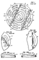
- Figure 1 is a plan view of a prior art, plate-type, valving element similar to those in the cited U.S. patents;
- Figures 2A and 2B are (a) a partial plan view of an edge of such a prior art, valving element, and (b) an illustration in simple line drawing of such a plate approaching contact with its valving plate, the angle of incidence being shown in exaggeration only to clarify the matter;
- Figures 3A and 3B are illustrations, generally corresponding with Figures 2A and 2B, representing the valving element (of Figures 2A and 2B) upon its having made contact with the valve seat, and showing a fatigue fracture occurring therein;
- Figure 4 is a plan view of a first embodiment of the valving element, according to the invention;
- Figure 5 is a greatly enlarged plan view of a portion of the valving element of Figure 4;
- Figures 6 and 7 are plan views, similar to that of Figure 5, depicting alternate embodiments of the invention; and
- Figure 8 is a plan view of the first embodiment of the invention, again with geometric reference lines superimposed thereon.
- As shown in Figs. 1 to 3, known plate-
type valving elements 10 commonly comprise aplate 12 having a circular edge orperiphery 14, and having a plurality of apertures, orflow ports 16, formed therethrough, theperiphery 14 and theflow ports 16 being concentric about theradial centre 18 of theplate 12. The apertures, orflow ports 16, are spaced in the radial direction bywebs 20, and in the circumferential direction by radially extendingligaments 22. Thewebs 20 andligaments 22 strengthen the plate. In use, theplates 12 are commonly cycled at a high rate, and almost impact on the complementary valve seat at an angle. Consequently, inwardly of the point of contact, bending occurs. Too soon, the plate metal fatigues and experiences afracture 24, usually through an area adjacent an end of a radially-outermost flow port 16. - In order to render such valving elements more durable and long-lived, the invention contemplates the strengthening thereof adjacent the ends of the
outermost flow ports 16, by spacing at least one end of suchoutermost flow ports 16 a greater distance from theperiphery 14 than the radial spacing of an intermediate part of such outermost flow passages from the periphery. This is achieved in one embodiment by configuring the periphery of the plate as a plurality of arcuate portions joined by rectilinear edge portions, the arcuate edge portions having a radius of curvature less than that of the arcuate flow apertures. This results in a plate 12a having an undulated or scalloped periphery 14a, as shown in the embodiment of Figs. 4 and 5. Therectilinear edge portions 26 avoid point-contact impacts. It can be seen that theoutermost flow ports 16 are substantially in parallel with most adjacent,flat edge sections 26 of the periphery 14a of the plate 12a. Theoutermost ports 16 are spaced between byarcuate sectors 28 which are substantially devoid of flow ports;sectors 28, for example, encompass areas subsisting between points "A" and "B", "C" and "D", and "E" and "F", andradius origins 30. - The
flow ports 16 subtend the angles "I", "II", "III" and, in fact, are concentric with theradial centre 32 of the plate 12a. Thesectors 28, however, are drawn on foreshortened radii from theorigins 30. Hence, they define plate portions, between theoutermost ports 16, which are like extendinglobes 34. By way of understanding a feature of the invention, eachoutermost port 16 may be considered to be subdivided into sections "a" through "e". The centre section "a', as can be seen, is more proximate to the edge or periphery 14a of the plate 12a than are the terminal sections "d" and "e". Increased spacing from the periphery 14a, for sections "d" and "e" is provided, therefore, by thearcuate sectors 28 orlobes 34 thereof, which, due to their foreshortened radii, define some of the undulation of the periphery 14a. - Each of the
outermost ports 16 has a pair ofsurfaces 36 and 36a which are tangent to an imaginary, broken,straight line 38 drawn therebetween. Thisline 38 may also be regarded as a chord to the arcuate inner edge of theoutermost ports 16.Lines 38 are parallel with the thereadjacentflat edge sections 26 of the periphery 14a, in thatsuch sections 26 are linear.Sections 26 obtain between peripheral points "B" and "C", and "E" and "A"; further ones thereof extend from points "D" and "F". - The ends of the
outermost ports 16, then, which were at risk in prior art, plate-type valving elements, are considerably more inboard of the periphery 14a in this embodiment of the invention. Such ends enjoy a greater,protective width 42 of plate material to isolate them from impacting shocks, and the latter shocks are more readily dissipated through thethereadjacent sectors 28. As for the greater, intermediate portions of theoutermost ports 16, they too are less subject to damaging shock. The thereadjacentlinear sections 26 can only effect a line contact, upon impactingly closing on a complementary valve seat (or stop plate). This defines a marked improvement over prior art valving elements which, for being wholly arcuate about the periphery thereof, unavoidably must sustain localized, point-contact impacts. - The plate 12a has a maximum
outside diameter 44, defined by thesectors 28 orlobes 34, and represented by a broken line, as well as a minimumoutside diameter 46, defined by thesections 26, and represented by a further broken line. The configuration of the plate 12a, then, comprises portions defined in part bysectors 28 orlobes 34 which are addendums to the minimumoutside diameter 46, and portions defined in part by thesections 26 which are dedendums from the maximumoutside diameter 44. - An alternative embodiment of the invention is shown in Figure 6, which is a fragmentary view, similar to Figure 5. Here too, the
outermost flow ports 16a of theplate 12b are arcuate but in this case they are of a lesser radius of curvature so that instead of being concentric formed through arcs drawn fromradial centres 48 which are about thecentre 32a of the plate each is concentric about aseparate centre 48 spaced radially outward from theradial centre 32a of theplate 12b. It is preferred that thecentres 48 be equally spaced from thecentre 32a. By this teaching, thevalve plate 12b may have a circular configuration of theperiphery 14b, concentric about thecentre 32a, although the ends of theoutermost ports 16a are spaced further from the periphery than an intermediate portion thereof so that these ends are protected from early fatigue and failure. Theports 16a have an arc of narrower angle and thus provide the increased radial dimension 42a between the outer ends thereof and a proximity thereof to theouter periphery 14b which would obtain ifports 16a were concentric withcentre 32a. To revert to Figure 1, such more narrowlyradiused ports 16a (as provided by this invention), and theirradial centres 48, are shown, thereon, in two locations, byports 16a depicted by broken or phantom lines. Thus it can be appreciated how simply the prior art valving elements can easily be improved by a practice of the invention. - As explained, and as shown in Figure 5, plate 12a is so configured as to define an improved, increasing spacing, of both of the ends, i.e. sections "d" and "e", of
outermost ports 16 from the edge or periphery 14a. Thelobes 34, however, defining the addendums to thediameter 46, extend further than thewidth 42 thereof obtaining at the port ends. The further alternative embodiment shown in Figure 7, comprises aplate 12c in which the maximum width afforded by thelobes 34 is used to protect first ends of theoutermost ports 16. - The Figure 7 embodiment has the lobes 34' and
linear sections 40 slightly rotated, relative to theoutermost ports 16. Accordingly, first ends, i.e., sections "e", of the latter ports are substantially in the midplane of thesectors 28. Sections "e", of the outermost ports, then, are at amaximum width 42b from the periphery 14c of theplate 12c. Second ends, i.e., sections "d" of theoutermost ports 16, are spaced apart from the periphery 14c no further, perhaps, than in the prior art plates. However, the latter ends or sections "d" subsist in approximately the midplane of the peripherallinear sections 40. Consequently, impacts are borne there along a line contact, and the impacting shock is more widely dispersed. - The geometric definitions of the invention are critical to its superior durability. Accordingly, to enhance the disclosure and its clarity, Figure 8 is provided. The latter corresponds to the first embodiment, as depicted in Figures 4 and 5. As shown in Figure 8, plate 12a has a first, central,
circular area 50 having an outer circumference 52; the latter is represented by a phantom circle, and is drawn from theplate centre 32 on a given radius. Plate 12a, then, has a second, outer,annular area 54 which is integral with, and in circumscription of,first area 50. Theradius origins 30 of thesectors 28 are traversed by the circumference 52, and thesectors 28, as depicted, are spaced apart from each other. - Each of the
sectors 28 is bounded by anarc 56 which is a portion of an imaginary circle 58 (two of which circles are represented in phantom).Arcs 56, ofadjacent sectors 28, orlobes 34, bisect atpoints 60 inarea 54. Then,radial lines 62, drawn radially outward from thecentre 32, and throughpoints 60, traverse the outermost apertures or flowports 16.Lines 62 subdivide these flow ports, traversing the midpoint of the length thereof. - The
arcs 56 extend through approximately fifty degrees, and on opposite sides of each they merge into tangency with the interveninglinear sections 26 of the periphery 14a. - It will be appreciated that the invention provides a valving element for a plate-type valve comprising a plate having flow apertures which are elongate about a given centre of the plate characterised in that at least one of the periphery of the plate and the outermost of the flow apertures considered radially of said centre is configured to provide a greater spacing between at least one end of such outermost apertures and the periphery of the plate than is provided between an intermediate part of said apertures and said periphery.
- With advantage the outermost apertures are arcuate and concentric about said centre, the periphery of the plate is configured as a plurality of spaced rectilinear edge portions joined by arcuate portions having a radius of curvature less than said outermost apertures, said at least one end of the outermost apertures lies on a radius with respect to said centre which intersects a peripheral arcuate portion and said intermediate portion lies on a radius which intersects a peripheral rectilinear edge portion.
- Preferably both ends of the outermost apertures lie on radii with respect to said centre one of which radii intersects a first peripheral arcuate position and the second of which radii intersects a second peripheral arucate portion.
- In an alternative embodiment the periphery of the plate is circular about the centre and the outermost apertures are arcuate to a radius of curvature less than that of the periphery.
Claims (19)
Priority Applications (4)
| Application Number | Priority Date | Filing Date | Title |
|---|---|---|---|
| US06/570,949 US4532959A (en) | 1984-01-16 | 1984-01-16 | Valving element for a plate-type valve |
| EP85304491A EP0208814B1 (en) | 1985-06-24 | 1985-06-24 | A valving element for a plate-type valve |
| DE8585304491T DE3579005D1 (en) | 1985-06-24 | 1985-06-24 | VALVE ELEMENT FOR PLATE VALVE. |
| AT85304491T ATE55175T1 (en) | 1985-06-24 | 1985-06-24 | VALVE ELEMENT FOR PLATE VALVE. |
Applications Claiming Priority (1)
| Application Number | Priority Date | Filing Date | Title |
|---|---|---|---|
| EP85304491A EP0208814B1 (en) | 1985-06-24 | 1985-06-24 | A valving element for a plate-type valve |
Publications (2)
| Publication Number | Publication Date |
|---|---|
| EP0208814A1 EP0208814A1 (en) | 1987-01-21 |
| EP0208814B1 true EP0208814B1 (en) | 1990-08-01 |
Family
ID=8194269
Family Applications (1)
| Application Number | Title | Priority Date | Filing Date |
|---|---|---|---|
| EP85304491A Expired EP0208814B1 (en) | 1984-01-16 | 1985-06-24 | A valving element for a plate-type valve |
Country Status (3)
| Country | Link |
|---|---|
| EP (1) | EP0208814B1 (en) |
| AT (1) | ATE55175T1 (en) |
| DE (1) | DE3579005D1 (en) |
Family Cites Families (6)
| Publication number | Priority date | Publication date | Assignee | Title |
|---|---|---|---|---|
| DE687507C (en) * | 1936-12-19 | 1940-01-31 | Laszlo Szigeth Dipl Ing | Automatic valve, especially for compressors |
| FR860126A (en) * | 1939-06-10 | 1941-01-07 | New valve | |
| DE6913300U (en) * | 1969-04-02 | 1969-12-18 | Bosch Gmbh Robert | AIR COMPRESSOR. |
| GB1287164A (en) * | 1970-04-28 | 1972-08-31 | Enfo Grundlagen Forschungs Ag | Improvements in or relating to piston compressors |
| AT306910B (en) * | 1971-02-19 | 1973-04-25 | Hoerbiger Ventilwerke Ag | Plate valve for reciprocating compressors |
| US4532959A (en) * | 1984-01-16 | 1985-08-06 | Ingersoll-Rand Company | Valving element for a plate-type valve |
-
1985
- 1985-06-24 DE DE8585304491T patent/DE3579005D1/en not_active Expired - Lifetime
- 1985-06-24 EP EP85304491A patent/EP0208814B1/en not_active Expired
- 1985-06-24 AT AT85304491T patent/ATE55175T1/en not_active IP Right Cessation
Also Published As
| Publication number | Publication date |
|---|---|
| EP0208814A1 (en) | 1987-01-21 |
| DE3579005D1 (en) | 1990-09-06 |
| ATE55175T1 (en) | 1990-08-15 |
Similar Documents
| Publication | Publication Date | Title |
|---|---|---|
| US11585451B2 (en) | Rotary disc valve | |
| US11572957B2 (en) | Rotary disc valve | |
| EP0807223B1 (en) | Compressor valve | |
| US8202185B2 (en) | Random elastomer cushion rings for a chain sprocket | |
| KR101118396B1 (en) | Multilayer metallic flat gasket, in particular cylinder head gasket | |
| US20010029981A1 (en) | Profiled plate valve | |
| FI60581C (en) | MALNINGSSKIVA | |
| US20220390027A1 (en) | Rotary Disc Valve | |
| US5036880A (en) | High efficiency plate valve for reciprocating compressor | |
| US4532959A (en) | Valving element for a plate-type valve | |
| US4172696A (en) | Low stress suction or discharge reed valve for compressor | |
| EP3274190B1 (en) | Dual dome convex tire tread block or tread rib | |
| EP0208814A1 (en) | A valving element for a plate-type valve | |
| US4574835A (en) | Valve component | |
| CA1058130A (en) | Valve closure parts | |
| CA1087066A (en) | Fluid pressure relief apparatus | |
| US4402342A (en) | Compressor valve | |
| EP1888949B1 (en) | Gasket | |
| US5029517A (en) | Vaneless rotary airlock valve | |
| CA1174955A (en) | Straight link studded tire chain | |
| GB2221744A (en) | Piston for a telescopic hydraulic vibration damper | |
| US4915673A (en) | Variable diameter pulley having extendible elements | |
| GB2085998A (en) | Device for fixing a cover on a housing | |
| JPH0553947B2 (en) | ||
| JP2025505737A (en) | Valve for a piston compressor and method for operating such a valve |
Legal Events
| Date | Code | Title | Description |
|---|---|---|---|
| PUAI | Public reference made under article 153(3) epc to a published international application that has entered the european phase |
Free format text: ORIGINAL CODE: 0009012 |
|
| AK | Designated contracting states |
Kind code of ref document: A1 Designated state(s): AT DE GB IT SE |
|
| TCAT | At: translation of patent claims filed | ||
| 17P | Request for examination filed |
Effective date: 19870403 |
|
| 17Q | First examination report despatched |
Effective date: 19880406 |
|
| GRAA | (expected) grant |
Free format text: ORIGINAL CODE: 0009210 |
|
| AK | Designated contracting states |
Kind code of ref document: B1 Designated state(s): AT DE GB IT SE |
|
| REF | Corresponds to: |
Ref document number: 55175 Country of ref document: AT Date of ref document: 19900815 Kind code of ref document: T |
|
| REF | Corresponds to: |
Ref document number: 3579005 Country of ref document: DE Date of ref document: 19900906 |
|
| ITF | It: translation for a ep patent filed | ||
| PLBE | No opposition filed within time limit |
Free format text: ORIGINAL CODE: 0009261 |
|
| STAA | Information on the status of an ep patent application or granted ep patent |
Free format text: STATUS: NO OPPOSITION FILED WITHIN TIME LIMIT |
|
| 26N | No opposition filed | ||
| ITTA | It: last paid annual fee | ||
| EAL | Se: european patent in force in sweden |
Ref document number: 85304491.5 |
|
| REG | Reference to a national code |
Ref country code: GB Ref legal event code: IF02 |
|
| PGFP | Annual fee paid to national office [announced via postgrant information from national office to epo] |
Ref country code: GB Payment date: 20030501 Year of fee payment: 19 |
|
| PGFP | Annual fee paid to national office [announced via postgrant information from national office to epo] |
Ref country code: AT Payment date: 20030502 Year of fee payment: 19 |
|
| PGFP | Annual fee paid to national office [announced via postgrant information from national office to epo] |
Ref country code: SE Payment date: 20030603 Year of fee payment: 19 |
|
| PGFP | Annual fee paid to national office [announced via postgrant information from national office to epo] |
Ref country code: DE Payment date: 20030630 Year of fee payment: 19 |
|
| PG25 | Lapsed in a contracting state [announced via postgrant information from national office to epo] |
Ref country code: GB Free format text: LAPSE BECAUSE OF NON-PAYMENT OF DUE FEES Effective date: 20040624 Ref country code: AT Free format text: LAPSE BECAUSE OF NON-PAYMENT OF DUE FEES Effective date: 20040624 |
|
| PG25 | Lapsed in a contracting state [announced via postgrant information from national office to epo] |
Ref country code: SE Free format text: LAPSE BECAUSE OF NON-PAYMENT OF DUE FEES Effective date: 20040625 |
|
| PG25 | Lapsed in a contracting state [announced via postgrant information from national office to epo] |
Ref country code: DE Free format text: LAPSE BECAUSE OF NON-PAYMENT OF DUE FEES Effective date: 20050101 |
|
| EUG | Se: european patent has lapsed | ||
| EUG | Se: european patent has lapsed | ||
| GBPC | Gb: european patent ceased through non-payment of renewal fee |
Effective date: 20040624 |