EP0208583B2 - Soldering iron - Google Patents
Soldering iron Download PDFInfo
- Publication number
- EP0208583B2 EP0208583B2 EP19860401324 EP86401324A EP0208583B2 EP 0208583 B2 EP0208583 B2 EP 0208583B2 EP 19860401324 EP19860401324 EP 19860401324 EP 86401324 A EP86401324 A EP 86401324A EP 0208583 B2 EP0208583 B2 EP 0208583B2
- Authority
- EP
- European Patent Office
- Prior art keywords
- stock
- soldering iron
- burner
- iron according
- flame
- Prior art date
- Legal status (The legal status is an assumption and is not a legal conclusion. Google has not performed a legal analysis and makes no representation as to the accuracy of the status listed.)
- Expired - Lifetime
Links
Images

Classifications
-
- B—PERFORMING OPERATIONS; TRANSPORTING
- B23—MACHINE TOOLS; METAL-WORKING NOT OTHERWISE PROVIDED FOR
- B23K—SOLDERING OR UNSOLDERING; WELDING; CLADDING OR PLATING BY SOLDERING OR WELDING; CUTTING BY APPLYING HEAT LOCALLY, e.g. FLAME CUTTING; WORKING BY LASER BEAM
- B23K3/00—Tools, devices, or special appurtenances for soldering, e.g. brazing, or unsoldering, not specially adapted for particular methods
- B23K3/02—Soldering irons; Bits
- B23K3/021—Flame-heated soldering irons
Definitions
- the invention relates to a soldering iron, which can be used in particular by roofers, zinc workers and tinsmiths for generally welding zinc, zinc-based composite metals or alloys, and metals or alloys in sheets coated or not, for example with synthetic material.
- soldering iron includes a heating body into which a powered burner opens. in combustible gas (for example propane) and in primary combustion air.
- a removable tip in general in copper, is mounted on the body and includes a tail which extends inside the body to be heated by the flame produced by the burner, and a part outside the body which is heated by conduction by the tail end and which is intended to be brought into contact with metals or alloys solder.
- the body also includes at least one orifice or opening for both ignition of the flame, at the entry of secondary air into the body for ventilation and the development of the flame, and at the outlet of the combustion gases, ignited or not.
- the flame produced by the burner is supplied with secondary air and licks the purlin tail to heat it.
- Such an iron is known for example from FR ⁇ A ⁇ 2 374 124.
- the heating element when it has large dimensions, prevents the use of the soldering iron in narrow places and, when it has smaller dimensions to be able to be used in these places, tightly surrounds the part of the tip of the burner which is opposite the burner, so that the flame produced by the burner cannot come lick only the surface of the purlin tail which faces the burner. This necessarily results in a rather slow rise in temperature of the external part of the purlin, greater consumption of gas for maintaining this external part of the purlin at a determined temperature, heating important of the walls of the heating body which surround the tail of breakdown. The flame is sometimes difficult to ignite and not very stable, in particular at very reduced flow of combustible gas.
- FR ⁇ A ⁇ 2 312 326 offers to have in the body, around the tip of the purlin, an annular flame-forming ramp, to produce a flame surrounding the tip of the purlin and oriented radially towards it.
- the result however a complication of the assembly and the assembly of the soldering iron, a greater sensitivity or brittleness to impact, and excessive heating of the tail end and therefore premature wear of this one.
- the present invention relates to a soldering iron which does not have the aforementioned drawbacks of the prior art and which, in particular, consumes less gas in normal operation, allows a rapid rise in temperature of the outer part of the tip, provides very high flame stability, in particular at a very reduced gas flow rate, and includes a space-saving heating body allowing the use of soldering iron in the narrowest areas.
- the invention provides a soldering iron according to claim 1.
- the invention makes it possible to maximize the heat exchange surface between the tail of failure housed in the body and the flame produced by the burner, and this without increasing the volume or tail tail mass and body clutter.
- This heating of the total surface of the purlin tail by the burner flame allows both reduce the total area of the purlin tail, and therefore the mass of the tail, to reduce by around 30% the time to warm up the outside of the tip, and reduce by around 40% the fuel gas consumption during normal operation.
- the front wall of the body and the surface facing the purlin tail define a space between them free, connected to the outside by the secondary air inlet port and allowing the circulation of secondary air around the purlin tail over the entire height thereof, substantially to the lower orifice of mounting of the tip in the body.
- the flame produced by the burner is necessarily caused to bypass the purlin tail and to lick the entire peripheral surface thereof, over the entire height of the purlin tail.
- the flame produced by the burner meets on its path a purlin tail section having an elongated shape substantially oval or elliptical whose major axis is in the axis of the burner, which promotes the progression of the flame along the surface of the purlin tail.
- Wavy or broken generators reduce the total volume and therefore the mass of the tail end, while increasing or at least retaining its total external surface and therefore its exchange surface thermal with flame.
- the hole for the axial fixing screw of the purlin tail is located upstream of the hole secondary air intake relative to the flame direction, which protects the screw from fixation.
- this tip can also be used on a soldering iron of the type with lateral attachment of the tail breakdown.
- the walls of the secondary air inlet orifice converging towards the outside of the body prevent flaming gases exiting through this orifice to spread outside the body and come to deteriorate or burn products located near the welding area.
- very few ignited gases exit the body through this orifice, and form a very small external flame.
- FIG. 1 representing a soldering iron of the prior art.
- This iron comprises, in a conventional manner, a heating body 10 comprising, at its rear part, an orifice axial 12 for mounting a burner 14 supplied with combustible gas and primary combustion air, the head of the burner comprising an axial orifice 16 and lateral orifices 18 for the outlet of combustible gas and air combustion primary.
- the lower wall of the body 10 has, at its front end, a lower mounting hole 20 a breakdown, the tail 24 of which is received inside the body 10 and the outer part 26 of which extends in oblique to the axis of the purlin tail 24.
- This purlin tail includes an annular groove 28, in which engages the end of a locking screw passing through a threaded hole 30 of a side wall of the body 10, and coming to support the purlin tail on the opposite side wall of the body.
- the upper wall of this body comprises two orifices 32 and 34 for the inlet of secondary air and for outlet of combustion gas, generally ignited, the orifice 32 having much larger dimensions than those of orifice 34 and being located upstream of the axis of the purlin tail relative to the direction of the flame, while the orifice 34 opens onto the end edge of the purlin tail 24, at neighborhood of the front part thereof.
- the front wall 36 of the body 10 closely surrounds the front surface of the purlin tail, to reduce the overall size of the body and facilitate its use in narrow areas.
- the flame produced by the burner is hooked on the outlets of the orifices of outlet 16 and 18 from the burner and flows inside the body 10 in the direction of the orifices 32 and 34, as shown in the drawing.
- the cylindrical half-surface of the purlin tail 24 which is oriented towards the end of the burner is heated, the opposite half-surface of the purlin tail not being made substantially by contact with the flame, and that in addition the lower half of the purlin tail 24, which is connected to the useful part 26 of the purlin tail, is less heated than its upper part on which is concentrated most of the flame.
- the support of the purlin tail on a side wall of the body prevents the flame to circulate in this area around the purlin tail.
- This soldering iron comprises a heating body 40, conventionally made of steel, and of which the rear end comprises an axial cylindrical conduit 42 into which the front end of a burner 44. At its rear end, the burner 44 receives an injector 46 of combustible gas, mounted by screwing into an injector holder 48 itself mounted by screwing to the rear end of the burner 44. A nut 50 slides around the injector holder 48 and allows connection to a device fuel gas supply.
- primary air inlet orifices 52 are formed in the cylindrical wall of the burner 44, at the outlet of the heater 46.
- a windproof sleeve 54 can be fixed to sealing on a shoulder of the burner body and remotely surrounds the orifices 52 of primary air inlet.
- the head or front end of the burner 44 comprises an axial orifice 56 for the outlet of combustible gas and primary air, and small lateral orifices 58, oriented radially with respect to the axis 60 of the burner, for form a single dart flame with flame attachment ring.
- the lower wall of the body 40 comprises an oblique front part 62 relative to the axis of the burner and in which is formed a cylindrical orifice 64 for mounting a purlin including the tail 66 of form general cylindrical extends inside the body 40 and whose outer part 68 extends coaxially to the purlin tail 66.
- a frustoconical flare 70 connects the purlin tail 66 to the outer part 68 and enables the outlet to the outside of the orifice 64 to be sealed.
- the upper end of the purlin tail 66 has a threaded axial hole 72 receiving a screw fixing 74 passing through an orifice 76 in the upper wall of the body 40.
- a washer 78 is interposed between the head of the screw 74 and the outlet of the orifice 76, to close this outlet substantially waterproof.
- the upper wall of the body 40 comprises, downstream of the orifice 76 and of the end of the purlin tail 66 relative to the burner 44, a single orifice 80 of secondary air inlet and gas outlet combustion, this orifice 80 having for example a trapezoidal shape whose axis of symmetry is in the longitudinal plane of symmetry of the soldering iron, this trapezoidal shape narrowing in direction of the front wall 82 of the body 40.
- This front wall 82 is inclined obliquely with respect to the purlin tail 66 and departs from the latter at from the lower orifice 64 for mounting the purlin in the body 40.
- the side walls 84 of the body 40 connected to the front wall 82, deviate obliquely from the purlin tail 66 from the sides of the lower front wall 62, towards the upper end of the body.
- This particular configuration of the heating body 40 allows, simultaneously, to reduce the external bulk of the body 40 on the side of the useful part 68 of the purlin, to allow the use soldering iron in very narrow areas, and also to form around the tip of the tip 66 a free space which surrounds the front cylindrical half-surface of the purlin tail and which is connected to the outside through port 80 so that secondary air entering body 40 through port 80 can circulate while around the front cylindrical half-surface of the purlin tail and over the entire height thereof.
- the single dart flame produced by the burner 44 and attached to the having end thereof can so develop inside the body all around the purlin tail 66, and just lick the whole outer surface thereof before moving towards the orifice 80 of secondary air inlet.
- the axis 60 of the burner meets the axis of the tail end at a point which is located in the lower half of the purlin tail, which promotes heating of this lower half.
- the angle formed by the axis of the purlin tail and the axis of the burner is approximately 45 °, which facilitates the flow of the flame along the peripheral surface of the purlin tail.
- the generators of the outer surface of the tail lines are wavy lines, for example sawtooth, which increases this area exterior and therefore the heat exchange surface with the flame while reducing the mass of the tail of breakdown.
- this outer surface may have an annular groove 86 with a flat bottom, intended to receive the end of a locking screw oriented perpendicular to the axis of the purlin tail, which allows the tip to be mounted in a soldering iron of the type shown in FIG. 1.
- the flow of combustible gas in the burner 44 causes the suction of primary combustion air in this burner through the orifices 52.
- the combustible mixture arriving in the body 40 is ignited, by example by means of the flame of a lighter introduced into the body through the orifice 80, or by means of any other suitable conventional device.
- the flame produced extends from the front end of the burner 44 to the orifice 80 by circulating over the entire outer surface of the purlin tail 66.
- the orifice 80 serves both to the inlet of secondary combustion air inside the body 40 and at the outlet of the combustion gases, which are usually inflamed and produce a small, not very visible flame on the top of the body 40.
- the walls of the orifice 80 are preferably convergent towards the outside of the body, as shown in FIG. 2.
- the useful part 68 of the tip is heated by conduction by the purlin tail 66 and is brought to the desired temperature, this being adjustable by adjustment of the gas flow rate supplying the burner 44.
Landscapes
- Engineering & Computer Science (AREA)
- Mechanical Engineering (AREA)
- Gas Burners (AREA)
Description
L'invention concerne un fer à souder, utilisable notamment par les couvreurs, lés zingueurs et les ferblantiers pour souder en général du zinc, des métaux ou alliages composites à base de zinc, et des métaux ou alliages en feuilles revêtues ou non par exemple de matière synthétique.The invention relates to a soldering iron, which can be used in particular by roofers, zinc workers and tinsmiths for generally welding zinc, zinc-based composite metals or alloys, and metals or alloys in sheets coated or not, for example with synthetic material.
On sait qu'un tel fer à souder comprend un corps de chauffe dans lequel débouche un brûleur alimenté en gaz combustible (par exemple du propane) et en air primaire de combustion. Une panne amovible, en général en cuivre, est montée sur le corps et comprend une queue qui s'étend à l'intérieur du corps pour être chauffée par la flamme produite par le brûleur, et une partie extérieure au corps qui est chauffée par conduction par la queue de panne et qui est destinée à être amenée au contact des métaux ou alliages à souder. Le corps comprend également au moins un orifice ou une ouverture servant à la fois à l'allumage de la flamme, à l'entrée d'air secondaire dans le corps pour l'aération et le développement de la flamme, et à la sortie des gaz de combustion, enflammés ou non.We know that such a soldering iron includes a heating body into which a powered burner opens. in combustible gas (for example propane) and in primary combustion air. A removable tip, in general in copper, is mounted on the body and includes a tail which extends inside the body to be heated by the flame produced by the burner, and a part outside the body which is heated by conduction by the tail end and which is intended to be brought into contact with metals or alloys solder. The body also includes at least one orifice or opening for both ignition of the flame, at the entry of secondary air into the body for ventilation and the development of the flame, and at the outlet of the combustion gases, ignited or not.
En fonctionnement, la flamme produite par le brûleur est alimentée en air secondaire et vient lécher la queue de panne pour la chauffer.In operation, the flame produced by the burner is supplied with secondary air and licks the purlin tail to heat it.
Un tel fer est connu par exemple par FR―A―2 374 124.Such an iron is known for example from FR ― A ― 2 374 124.
Ces fers souffrent en général d'un certain nombre d'inconvénients. Le corps de chauffe, lorsqu'il a des dimensions importantes, empêche l'utilisation du fer à souder dans les endroits étroits et, lorsqu'il a des dimensions plus faibles pour pouvoir être utilisé dans ces endroits, entoure étroitement la partie de la queue de panne qui est à l'opposé du brûleur, de sorte que la flamme produite par le brûleur ne peut venir lécher que la surface de la queue de panne qui est tournée vers le brûleur. Il en résulte nécessairement une montée en température assez lente de la partie extérieure de la panne, une plus grande consommation de gaz pour le maintien de cette partie extérieure de la panne à une température déterminée, un chauffage important des parois du corps de chauffe qui entourent la queue de panne. La flamme est parfois difficile à allumer et peu stable, notamment à débit très réduit de gaz combustible.These irons generally suffer from a certain number of drawbacks. The heating element, when it has large dimensions, prevents the use of the soldering iron in narrow places and, when it has smaller dimensions to be able to be used in these places, tightly surrounds the part of the tip of the burner which is opposite the burner, so that the flame produced by the burner cannot come lick only the surface of the purlin tail which faces the burner. This necessarily results in a rather slow rise in temperature of the external part of the purlin, greater consumption of gas for maintaining this external part of the purlin at a determined temperature, heating important of the walls of the heating body which surround the tail of breakdown. The flame is sometimes difficult to ignite and not very stable, in particular at very reduced flow of combustible gas.
Pour tenter d'améliorer le chauffage de la queue de panne par la flamme, FR―A―2 312 326 propose de disposer dans le corps, autour de la queue de panne, une rampe annulaire de formation de flamme, pour produire une flamme entourant la queue de panne et orientée radialement vers celle-ci. Il en résulte toutefois une complication du montage et de l'assemblage du fer à souder, une plus grande sensibilité ou fragilité aux chocs, et un chauffage trop important de la queue de panne et donc une usure prématurée de celle-ci.To try to improve the heating of the tail end by the flame, FR ― A ― 2 312 326 offers to have in the body, around the tip of the purlin, an annular flame-forming ramp, to produce a flame surrounding the tip of the purlin and oriented radially towards it. The result however a complication of the assembly and the assembly of the soldering iron, a greater sensitivity or brittleness to impact, and excessive heating of the tail end and therefore premature wear of this one.
La présente invention a pour objet un fer à souder qui ne présente par les inconvénients précités de la technique antérieure et qui, notamment, consomme moins de gaz en fonctionnement normal, permet une montée en température rapide de la partie extérieure de la panne, offre une très grande stabilité de flamme, notamment à débit de gaz très réduit, et comprend un corps de chauffe à encombrement faible permettant l'utilisation du fer à souder dans les zones les plus étroites.The present invention relates to a soldering iron which does not have the aforementioned drawbacks of the prior art and which, in particular, consumes less gas in normal operation, allows a rapid rise in temperature of the outer part of the tip, provides very high flame stability, in particular at a very reduced gas flow rate, and includes a space-saving heating body allowing the use of soldering iron in the narrowest areas.
A cet effet, l'invention propose un fer à souder selon la revendication 1.To this end, the invention provides a soldering iron according to claim 1.
L'invention permet d'augmenter à un maximum la surface d'échange thermique entre la queue de panne logée dans le corps et la flamme produite par le brûleur, et cela sans augmenter le volume ou la masse de la queue de panne et l'encombrement du corps.The invention makes it possible to maximize the heat exchange surface between the tail of failure housed in the body and the flame produced by the burner, and this without increasing the volume or tail tail mass and body clutter.
C'est essentiellement grâce à l'aménagement du circuit d'air secondaire à l'intérieur du corps de chauffe que la flamme produite par le brûleur peut venir lécher toute la surface de la queue de panne, sans qu'il soit nécessaire pour cela de disposer dans le corps une rampe annulaire de formation de flamme autour de la queue de panne.This is mainly thanks to the arrangement of the secondary air circuit inside the body of heats up as the flame produced by the burner can lick the entire surface of the purlin tail, without that it is necessary for this to have in the body an annular flame-forming ramp around the tail end.
Ce chauffage de la surface totale de la queue de panne par la flamme du brûleur permet à la fois de réduire la surface totale de la queue de panne, et donc la masse de celle-ci, de réduire de 30% environ le temps de mise à température de la partie extérieure de la panne, et de réduire d'environ 40% la consommation de gaz combustible en fonctionnement normal.This heating of the total surface of the purlin tail by the burner flame allows both reduce the total area of the purlin tail, and therefore the mass of the tail, to reduce by around 30% the time to warm up the outside of the tip, and reduce by around 40% the fuel gas consumption during normal operation.
Des caractéristiques additionelles de l'invention sont énoncées dans les revendications 2 et suivantes.Additional features of the invention are set out in claims 2 and following.
La paroi avant du corps et la surface en regard de la queue de panne délimitent entre elles un espace libre, relié à l'extérieur par l'orifice d'entrée d'air secondaire et permettant la circulation de l'air secondaire autour de la queue de panne sur toute la hauteur de celle-ci, sensiblement jusqu'à l'orifice inférieur de montage de la panne dans le corps.The front wall of the body and the surface facing the purlin tail define a space between them free, connected to the outside by the secondary air inlet port and allowing the circulation of secondary air around the purlin tail over the entire height thereof, substantially to the lower orifice of mounting of the tip in the body.
Ainsi, la flamme produite par le brûleur est nécessairement amenée à contourner la queue de panne et à lécher toute la surface périphérique de celle-ci, sur toute la hauteur de la queue de panne.Thus, the flame produced by the burner is necessarily caused to bypass the purlin tail and to lick the entire peripheral surface thereof, over the entire height of the purlin tail.
Grâce à l'inclinaison de la queue de panne sur l'axe du brûleur, la flamme produite par le brûleur rencontre sur son trajet une section de queue de panne ayant une forme allongée sensiblement ovale ou elliptique dont le grand axe est dans l'axe du brûleur, ce qui favorise la progression de la flamme le long de la surface de la queue de panne.Thanks to the inclination of the tip of the purlin on the axis of the burner, the flame produced by the burner meets on its path a purlin tail section having an elongated shape substantially oval or elliptical whose major axis is in the axis of the burner, which promotes the progression of the flame along the surface of the purlin tail.
Des génératrices ondulés on brisées réduisent le volume total et donc la masse de la queue de panne, tout en augmentant ou au moins en conservant sa surface extérieure totale et donc sa surface d'échange thermique avec la flamme.Wavy or broken generators reduce the total volume and therefore the mass of the tail end, while increasing or at least retaining its total external surface and therefore its exchange surface thermal with flame.
L'orifice de passage de la vis de fixation axiale de la queue de panne se trouve en amont de l'orifice d'entrée d'air secondaire par rapport à la direction de la flamme, ce qui permet de protéger la vis de fixation. The hole for the axial fixing screw of the purlin tail is located upstream of the hole secondary air intake relative to the flame direction, which protects the screw from fixation.
Lorsque la surface extérieure de la queue de panne comprend une partie intermédiaire en forme de gorge, cette panne peut être utilisée également sur un fer à souder du type à fixation latérale de la queue de panne.When the outer surface of the purlin tail includes an intermediate part in the form of groove, this tip can also be used on a soldering iron of the type with lateral attachment of the tail breakdown.
Dans le cas où le volume intérieure du corps de chauffe a, perpendiculairement à l'axe de la queue de panne, une section droite qui diminue progressivement de son extrémité supérieure jusqu'à l'orifice inférieur de montage de la panne, il en résulte un encombrement plus faible de ce corps de chauffe du côté de la panne, ce qui rend le fer à souder plus facile à utiliser dans les endroits étroits.In the case where the internal volume of the heating body has, perpendicular to the axis of the tail purlin, a straight section which gradually decreases from its upper end to the orifice lower mounting of the tip, this results in a smaller footprint of this heater on the side tip, which makes the soldering iron easier to use in tight places.
Les parois de l'orifice d'entrée d'air secondaire convergentes vers l'extérieur du corps empêchent les gaz enflammés sortant par cet orifice de s'étaler à l'extérieur du corps et de venir détériorer ou brûler des produits situés au voisinage de la zone de soudure. En fait, grâce à l'invention, très peu de gaz enflammés sortent du corps par cet orifice, et forment une très petite flamme extérieure.The walls of the secondary air inlet orifice converging towards the outside of the body prevent flaming gases exiting through this orifice to spread outside the body and come to deteriorate or burn products located near the welding area. In fact, thanks to the invention, very few ignited gases exit the body through this orifice, and form a very small external flame.
Dans la description qui suit, faite à titre d'exemple, on se réfère aux dessins annexés, dans lesquels:
On se réfère d'abord à la figure 1, représentant un fer à souder de la technique antérieure.We first refer to FIG. 1, representing a soldering iron of the prior art.
Ce fer comprend, de façon classique, un corps de chauffe 10 comprenant, à sa partie arrière, un orifice
axial 12 de montage d'un brûleur 14 alimenté en gaz combustible et en air primaire de combustion, la tête
du brûleur comprenant un orifice axial 16 et des orifices latéraux 18 de sortie de gaz combustible et d'air
primaire de combustion.This iron comprises, in a conventional manner, a
La paroi inférieure du corps 10 présente, à son extrémité avant, un orifice inférieur 20 de montage
d'une panne, dont la queue 24 est reçue à l'intérieur du corps 10 et dont la partie extérieure 26 s'étend en
oblique par rapport à l'axe de la queue de panne 24. Cette queue de panne comprend une gorge annulaire
28, dans laquelle s'engage l'extrémité d'une vis de blocage passant par un trou fileté 30 d'une paroi latérale
du corps 10, et venant appuyer la queue de panne sur la paroi latérale opposée du corps.The lower wall of the
La paroi supérieure de ce corps comprend deux orifices 32 et 34 d'entrée d'air secondaire et de sortie
de gaz de combustion, en général enflammé, l'orifice 32 ayant des dimensions beaucoup plus imporantes
que celles de l'orifice 34 et étant situé en amont de l'axe de la queue de panne par rapport à la direction de
la flamme, tandis que l'orifice 34 débouche sur la tranche d'extrémité de la queue de panne 24, au
voisinage de la partie avant de celle-ci.The upper wall of this body comprises two
La paroi avant 36 du corps 10 entoure étroitement la surface avant de la queue de panne, pour
diminuer l'encombrement général du corps et faciliter son utilisation dans les zones étroites.The
En fonctionnement, la flamme produite par le brûleur est accrochée sur les débouchés des orifices de
sortie 16 et 18 du brûleur et circule à l'intérieur du corps 10 en direction des orifices 32 et 34, comme
représenté sur le dessin. Il en résulte que seule la demi-surface cylindrique de la queue de panne 24 qui est
orientée vers l'extrémité du brûleur est chauffée, la demi-surface opposée de la queue de panne n'étant en
fait sensiblement par au contact avec la flamme, et qu'en outre la moitié inférieure de la queue de panne 24,
qui est reliée à la partie utile 26 de la queue de panne, est moins chauffée que sa partie supérieure sur
laquelle est concentrée la plus grande partie de la flamme.In operation, the flame produced by the burner is hooked on the outlets of the orifices of
La disposition des orifices 32 et 34 d'entrée d'air secondaire dans le corps, et la très faible section
transversale de l'espace compris entre la paroi avant 36 du corps et la surface avant de la queue de panne
24 interdisent la circulation d'air secondaire dans cet espace et donc le développement d'une flamme sur la
surface avant du corps. De plus, l'appui de la queue de panne sur une paroi latérale du corps empêche la
flamme de circuler dans cette zone autour de la queue de panne.The arrangement of the
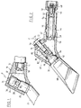
On se référe maintenant aux figures 2, 3 et 4 représentant un fer à souder selon l'invention.Referring now to Figures 2, 3 and 4 showing a soldering iron according to the invention.
Ce fer à souder comprend un corps de chauffe 40, réalisé de façon classique en fonte aciérée, et dont
l'extrémité arrière comprend un conduit cylindrique axiale 42 dans lequel est vissée l'extrémité avant d'un
brûleur 44. A son extrémite arrière, le brûleur 44 reçoit un injecteur 46 de gaz combustible, monté par
vissage dans un porte-injecteur 48 lui-même monté par vissage à l'extrémité arrière du brûleur 44. Un
écrou 50 entoure à coulissement le porte-injecteur 48 et permet le raccordement à un dispositif
d'alimentation en gaz combustible.This soldering iron comprises a
De façon classique, des orifices 52 d'entrée d'air primaire sont formés dans la paroi cylindrique du
brûleur 44, au débouché de l'intecteur 46. Un manchon pare-vent 54 peut être fixé à étanchéité sur un
épaulement du corps du brûleur et entoure à distance les orifices 52 d'entrée d'air primaire.Conventionally, primary
La tête ou extrémité avant du brûleur 44 comprend un orifice axial 56 de sortie de gaz combustible et
d'air primaire, et de petits orifices latéraux 58, orientés radialement par rapport à l'axe 60 du brûleur, pour
former une flamme à dard unique avec anneau d'accrochage de la flamme.The head or front end of the
La paroi inférieure du corps 40 comprend une partie avant oblique 62 par rapport à l'axe du brûleur et
dans laquelle est formé un orifice cylindrique 64 de montage d'une panne dont la queue 66 de forme
générale cylidrique s'étend à l'intérieur du corps 40 et dont la partie extérieure 68 s'étend coaxialement à la
queue de panne 66. Un évasement tronconique 70 relie la queue de panne 66 à la partie extérieure 68 et
permet de fermer de façon étanche le débouché vers l'extérieur de l'orifice 64.The lower wall of the
L'extrémité supérieure de la queue de panne 66 présente un trou axial taraudé 72 recevant une vis de
fixation 74 passant dans un orifice 76 de la paroi supérieure du corps 40. Une rondelle 78 est interposée
entre la tête de la vis 74 et le débouché de l'orifice 76, pour fermer ce débouché de façon sensiblement
étanche.The upper end of the
La paroi supérieure du corps 40 comprend, en aval de l'orifice 76 et de l'extrémité de la queue de panne
66 par rapport au brûleur 44, un orifice unique 80 d'entrée d'air secondaire et de sortie de gaz de
combustion, cet orifice 80 ayant par exemple une forme trapézoïdale dont l'axe de symétrie se trouve dans
le plan longitudinal de symétrie du fer à souder, cette forme trapézoïdale allant en se rétrécissant en
direction de la paroi avant 82 du corps 40.The upper wall of the
Cette paroi avant 82 est inclinée en oblique par rapport à la queue de panne 66 et s'écarte de celle-ci à
partir de l'orifice inférieur 64 de montage de la panne dans le corps 40. De même, les parois latérales 84 du
corps 40, reliées à l a paroi avant 82, s'écartent en oblique de la queue de panne 66 à partir des côtés de la
paroi inférieure avant 62, en direction de l'extrémité supérieure du corps.This
Cette configuration particulière du corps de chauffe 40 permet, simultanément, de réduire
l'encombrement extérieur du corps 40 du côté de la partie utile 68 de la panne, pour permettre l'utilisation
du fer à souder dans des zones très étroites, et également de former autour de la queue de panne 66 un
espace libre qui entoure la demi-surface cylindrique avant de la queue de panne et qui est relié à l'extérieur
par l'orifice 80 de telle sorte que l'air secondaire entrant dans le corps 40 par l'orifice 80 peut circuler tout
autour de la demi-surface cylindrique avant de la queue de panne et sur toute la hauteur de celle-ci.This particular configuration of the
La flamme à dard unique produite par le brûleur 44 et accrochée à l'extrémité ayant de celui-ci peut
donc se développer à l'intérieur du corps tout autour de la queue de panne 66, et vient lécher toute la
surface extérieure de celle-ci avant de se diriger vers l'orifice 80 d'entrée d'air secondaire.The single dart flame produced by the
Si l'on considère un plan P passant par l'axe de la queue de panne et perpendiculaire au plan du dessin en figures 1 et 2, on voit que, dans le fer selon l'invention, la flamme circule sur toute la surface semi-cylindrique de la queue de panne se trouvant en amont du plan P, puis traverse le plan P et circule sur toute la surface semi-cylindrique de queue de panne en aval du plan P.If we consider a plane P passing through the axis of the purlin tail and perpendicular to the plane of the drawing in Figures 1 and 2, it can be seen that, in the iron according to the invention, the flame circulates over the entire semi-cylindrical surface of the tail of the fault located upstream of the plane P, then crosses the plane P and circulates on all the semi-cylindrical surface of the tail end downstream of the plane P.
Dans le fer de la figure 1, une fraction importante (environ les 3/4) de la flamme circule sur la moitié
supérieure de la surface semi-cylindrique de la queue de panne se trouvant en amont du plan P et se dirige
vers l'orifice 32, sans traverser le plan P, et la fraction restante (1/4) de la flamme circule sur environ 1/4 de
la surface semi-cylindrique de la queue de panne en amont du plan P et sur environ 1/3 de la surface semi-cylindrique
de queue de panne en aval du plan P pour se diriger vers l'orifice 34.In the iron of figure 1, a large fraction (about 3/4) of the flame circulates over half
upper of the semi-cylindrical surface of the purlin tail located upstream of the plane P and goes
towards
Comme l'énergie thermique cédée à la queue de panne est proportionnelle à l'énergie thermique de la
flamme et à la surface chauffée de la queue de panne soit
En outre, l'axe 60 du brûleur vient rencontrer l'axe de la queue de panne en un point qui est situé dans
la moitié inférieure de la queue de panne, ce qui favorise le chauffage de cette moitié inférieure. L'angle
formé par l'axe de la queue de panne et l'axe du brûleur est d'environ 45°, ce qui facilite l'écoulement de la
flamme le long de la surface périphérique de la queue de panne.In addition, the
Avantageusement, comme on le voit en figure 2, les génératrices de la surface extérieure de la queue de panne sont des lignes ondulées, par exemple en dents de scie, ce qui permet d'augmenter cette surface extérieure et donc la surface d'échange thermique avec la flamme tout en réduisant la masse de la queue de panne.Advantageously, as can be seen in FIG. 2, the generators of the outer surface of the tail lines are wavy lines, for example sawtooth, which increases this area exterior and therefore the heat exchange surface with the flame while reducing the mass of the tail of breakdown.
Par ailleurs, cette surface extérieure peut présenter une gorge annulaire 86 à fond plat, destinée à
recevoir l'extrémité d'une vis de blocage orientée perpendiculairement à l'axe de la queue de panne, ce qui
permet le montage de la panne dans un fer à souder du type de celui représenté en figure 1.Furthermore, this outer surface may have an
Le fonctionnement du fer à souder selon l'invention découle à l'évidence de ce qui précède:The operation of the soldering iron according to the invention obviously follows from the above:
Le débit de gaz combustible dans le brûleur 44 provoque l'aspiration d'air primaire de combustion
dans ce brûleur par les orifices 52. Le mélange combustible arrivant dans le corps 40 est allumé, par
exemple au moyen de la flamme d'un briquet introduite dans le corps par l'orifice 80, ou au moyen de tout
autre dispositif classique approprié. La flamme produite s'étend de l'extrémité avant du brûleur 44 jusqu'à
l'orifice 80 en circulant sur toute la surface extérieure de la queue de panne 66. L'orifice 80 sert à la fois à
l'entrée d'air secondaire de combustion à l'intérieur du corps 40 et à la sortie des gaz de combustion, qui
sont en général enflammés et produisent une petite flamme peu visible sur le dessus du corps 40. Pour
concentrer cette flamme et éviter son étalement, les parois de l'orifice 80 sont, de préférence, convergentes
vers l'extérieur du corps, comme représenté en figure 2. La partie utile 68 de la panne est chauffée par
conduction par la queue de panne 66 et est portée à la température voulue, celle-ci étant réglable par
réglage du débit de gaz alimentant le brûleur 44.The flow of combustible gas in the
Le fer à souder selon l'invention présente, par rapport à la technique antérieure selon la Figure 1,
les avantages suivants:
Claims (14)
- A soldering iron for use in narrow working areas, comprising a burner (44) having at its rear part inlets for combustible gas (46) and for primary combustion air (52) and opening out with its forward end into a heater body (40), and a bit (66,68) passing through and stopping a bottom opening (64) of the body in such a way that the bit stock (66) is received inside the body (40) facing the burner (44), while the working portion (68) of the bit projects downwards outside the body, the body having a top wall facing the end of the stock and the inside of the body communicating with the outside through at least one opening (80) provided in the top wall, allowing the admission of secondary air and the exhaustion of the flame and the combustion gases, characterized in that the opening for admitting secondary air and for exhausting flame and combustion gases (80), or the center of gravity of the openings for admitting secondary air and for exhausting flame and combustion gases, is situated downstream from the stock relative to the burner when the soldering iron is viewed from above along the axis of the stock, the surface of the stock and the wall (82) of the heater body delimiting a space which communicates freely with the same openings for allowing a flow of secondary air and combustion gases and a spreading of the flame produced by the burner around all of the front half-surface of the stock.
- A soldering iron according to claim 1, characterized in that the axis (60) of the burner (44) is directed towards the bottom half of the stock (66).
- A soldering iron according to one of claims 1 and 2, characterized in that the said free space extends substantially right up to the bit mounting opening (64).
- A soldering iron according to claim 3, characterized in that the cross section of the said free space increases progressively towards the opening (80) for admitting secondary air.
- A soldering iron according to any preceding claim, characterized in that the burner (44) is of the type having a single tip directed along the burner axis and in that the axis of the stock (66) is obliquely inclined to the burner axis.
- A soldering iron according to claim 5, characterized in that the angle between the burner axis and the axis of the stock (66) is about 45°.
- A soldering iron according to any preceding claim, characterized in that the inside volume of the body (40) has a right cross section perpendicular to the axis of the stock which diminishes progressively from its top end towards the bit mounting opening (64).
- A soldering iron according to any preceding claim, characterized in that the walls of the opening (80) for admitting secondary air converge towards the outside of the body.
- A soldering iron according to any preceding claim, characterized in that the stock (66) is substantially cylindrical in shape with varying circular cross section, its cylindrical outside surface being generated by wavy lines or by zig-zag lines, e.g. sawtooth lines.
- A soldering iron according to any preceding claim, characterized in that the stock (66) is fixed axially in the body (40) and includes an internally tapped hole (72) at its top end receiving a fixing screw (74) passing through an orifice (76) in the top portion of the body.
- A soldering iron according to claim 10, characterized in that the bit has a frusto-conical flare (70) between its stock (66) and its external portion (68), which flare bears against the edge of the bit mounting opening (64).
- A soldering iron according to any preceding claim, characterized in that the orifice (80) for admitting secondary air and for exhausting flame and combustion gases from the heater body (40) is formed on the top of the body (40).
- A soldering iron according to any preceding claim, characterized in that the surface of the stock includes an intermediate portion (86) in the form of a groove enabling the stock to be fixed laterally in the body by means of a lock screw directed perpendicularly to the axis of the stock.
- A soldering iron according to one of claims 10 and 11, characterized in that the tightening of the fixing screw leaves a remaining interval between the top end of the stock and the facing wall of the body.
Applications Claiming Priority (2)
| Application Number | Priority Date | Filing Date | Title |
|---|---|---|---|
| FR8509249A FR2583324B1 (en) | 1985-06-18 | 1985-06-18 | SOLDERING IRON |
| FR8509249 | 1985-06-18 |
Publications (3)
| Publication Number | Publication Date |
|---|---|
| EP0208583A1 EP0208583A1 (en) | 1987-01-14 |
| EP0208583B1 EP0208583B1 (en) | 1990-09-05 |
| EP0208583B2 true EP0208583B2 (en) | 1999-03-03 |
Family
ID=9320382
Family Applications (1)
| Application Number | Title | Priority Date | Filing Date |
|---|---|---|---|
| EP19860401324 Expired - Lifetime EP0208583B2 (en) | 1985-06-18 | 1986-06-17 | Soldering iron |
Country Status (3)
| Country | Link |
|---|---|
| EP (1) | EP0208583B2 (en) |
| DE (1) | DE3673899D1 (en) |
| FR (1) | FR2583324B1 (en) |
Families Citing this family (5)
| Publication number | Priority date | Publication date | Assignee | Title |
|---|---|---|---|---|
| DE3819309A1 (en) * | 1988-06-05 | 1989-12-14 | Wolfram Bensch | Gas-soldering bit |
| DE29605169U1 (en) * | 1996-03-20 | 1996-12-05 | J. Lorch Ges. & Co. KG, 71111 Waldenbuch | soldering iron |
| FR2764535B1 (en) * | 1997-06-11 | 1999-09-03 | Guilbert Express Sa | OPTIMIZED FLAME COVER SOLDERING IRON |
| DE10052738C1 (en) * | 2000-10-25 | 2002-06-13 | Rothenberger Werkzeuge Ag | Combustion chamber soldering iron |
| FR3073034B1 (en) * | 2017-10-27 | 2019-11-08 | Guilbert Express | GAS COMBUSTION HEATING TOOL, PARTICULARLY OF SOLDERING IRON OR ECORNER TYPE |
Family Cites Families (3)
| Publication number | Priority date | Publication date | Assignee | Title |
|---|---|---|---|---|
| GB641797A (en) * | 1947-04-24 | 1950-08-23 | Albert Horace Greaves | Improvements in and relating to gas heated soldering tools |
| FR2312326A1 (en) * | 1975-05-30 | 1976-12-24 | Guilbert Et Fils Anciens Ets | Gas heated soldering iron - where gas flame passes through ring nozzle for uniform heating of soldering bit |
| FR2374124A1 (en) * | 1976-12-15 | 1978-07-13 | Rippes Sa | Soldering iron - has tip of variable orientation, for use in areas of poor accessibility |
-
1985
- 1985-06-18 FR FR8509249A patent/FR2583324B1/en not_active Expired
-
1986
- 1986-06-17 DE DE8686401324T patent/DE3673899D1/en not_active Expired - Lifetime
- 1986-06-17 EP EP19860401324 patent/EP0208583B2/en not_active Expired - Lifetime
Also Published As
| Publication number | Publication date |
|---|---|
| DE3673899D1 (en) | 1990-10-11 |
| EP0208583A1 (en) | 1987-01-14 |
| FR2583324B1 (en) | 1989-11-03 |
| FR2583324A1 (en) | 1986-12-19 |
| EP0208583B1 (en) | 1990-09-05 |
Similar Documents
| Publication | Publication Date | Title |
|---|---|---|
| CA2752093C (en) | Door with a built-in burner for a heating appliance | |
| CA1302227C (en) | Heating apparatus with catalytic burner | |
| EP0208583B2 (en) | Soldering iron | |
| EP2037174B1 (en) | Handtool with improved gas combustion | |
| EP0270424A1 (en) | Ignition device for a high-speed burner with a cold nozzle, and burner using this device | |
| FR2972789A1 (en) | CONDENSING GAS HEATING APPARATUS | |
| FR2945758A1 (en) | HAND TOOL WITH INCORPORATED GAS DETENDOR WITH DETERENT TEMPERATURE CONTROL SYSTEM | |
| FR2628291A1 (en) | DEVICE FOR BURNING HORNS OF FARMED ANIMALS | |
| FR2461196A1 (en) | LIQUID HYDROCARBON BURNER PRODUCING A BLUE FLAME | |
| EP0094890A1 (en) | Boiler using solid fuel of the tube radiation furnace type, method for the transformation of a boiler and device for carrying it out | |
| FR2619891A1 (en) | Gas-burner head | |
| FR2655711A1 (en) | Burner for a gaseous air-fuel mixture | |
| FR2745891A1 (en) | Atmospheric gas burner | |
| FR2732447A1 (en) | Petrol-fuelled burner with multi-part combustion head | |
| FR2570473A1 (en) | Improvements to gas boilers with parallel flow comprising a rose and a flame retention baffle (hub) relating to gas boilers and independent supply of combustion air | |
| FR2859120A1 (en) | Gas combustion soldering iron comprises peen on which and through which combustion products are introduced to improve heating | |
| FR3033625A1 (en) | SOLID FUEL BURNER AND HEATING APPARATUS COMPRISING SUCH A BURNER | |
| FR2621102A1 (en) | BURNER FOR A DEVICE FOR BURNING SOLID PARTICLES CONTAINED IN THE EXHAUST GASES OF INTERNAL COMBUSTION ENGINES | |
| CA2288079A1 (en) | Heating apparatus | |
| FR2993346A1 (en) | GRANULAR OR PELLET BOILER WITH CYCLONIC COMBUSTION | |
| FR2811410A1 (en) | INCREASED GAS AND AIR MIXTURE BURNER | |
| FR2936040A1 (en) | BOILER MIXER | |
| FR2719361A1 (en) | Improvements to gas burners. | |
| CH351698A (en) | Liquid fuel burner | |
| FR2765953A1 (en) | Weed burner used in agriculture or gardening |
Legal Events
| Date | Code | Title | Description |
|---|---|---|---|
| PUAI | Public reference made under article 153(3) epc to a published international application that has entered the european phase |
Free format text: ORIGINAL CODE: 0009012 |
|
| AK | Designated contracting states |
Kind code of ref document: A1 Designated state(s): BE CH DE GB LI NL SE |
|
| 17P | Request for examination filed |
Effective date: 19870518 |
|
| 17Q | First examination report despatched |
Effective date: 19880722 |
|
| GRAA | (expected) grant |
Free format text: ORIGINAL CODE: 0009210 |
|
| AK | Designated contracting states |
Kind code of ref document: B1 Designated state(s): BE CH DE GB LI NL SE |
|
| PG25 | Lapsed in a contracting state [announced via postgrant information from national office to epo] |
Ref country code: SE Effective date: 19900905 Ref country code: NL Free format text: LAPSE BECAUSE OF FAILURE TO SUBMIT A TRANSLATION OF THE DESCRIPTION OR TO PAY THE FEE WITHIN THE PRESCRIBED TIME-LIMIT Effective date: 19900905 Ref country code: GB Effective date: 19900905 |
|
| REF | Corresponds to: |
Ref document number: 3673899 Country of ref document: DE Date of ref document: 19901011 |
|
| GBV | Gb: ep patent (uk) treated as always having been void in accordance with gb section 77(7)/1977 [no translation filed] | ||
| PLBI | Opposition filed |
Free format text: ORIGINAL CODE: 0009260 |
|
| PLBI | Opposition filed |
Free format text: ORIGINAL CODE: 0009260 |
|
| 26 | Opposition filed |
Opponent name: SOCIETE VIRAX Effective date: 19910603 |
|
| 26 | Opposition filed |
Opponent name: ROTHENBERGER WERKZEUGE- MASCHINEN GMBH Effective date: 19910531 Opponent name: SOCIETE VIRAX Effective date: 19910603 |
|
| NLR1 | Nl: opposition has been filed with the epo |
Opponent name: ROTHENBERGER WERKZEUGE- MASCHINEN GMBH. Opponent name: SOCIETE VIRAX |
|
| PLBQ | Unpublished change to opponent data |
Free format text: ORIGINAL CODE: EPIDOS OPPO |
|
| PLAB | Opposition data, opponent's data or that of the opponent's representative modified |
Free format text: ORIGINAL CODE: 0009299OPPO |
|
| PLAB | Opposition data, opponent's data or that of the opponent's representative modified |
Free format text: ORIGINAL CODE: 0009299OPPO |
|
| PLBQ | Unpublished change to opponent data |
Free format text: ORIGINAL CODE: EPIDOS OPPO |
|
| R26 | Opposition filed (corrected) |
Opponent name: SOCIETE VIRAX * 910531 ROTHENBERGER WERKZEUGE- MAS Effective date: 19910603 |
|
| R26 | Opposition filed (corrected) |
Opponent name: SOCIETE VIRAX * 910531 ROTHENBERGER WERKZEUGE- MAS Effective date: 19910603 |
|
| NLR1 | Nl: opposition has been filed with the epo |
Opponent name: ROTHENBERGER WERKZEUGE- MASCHINEN GMBH Opponent name: SOCIETE VIRAX |
|
| APAC | Appeal dossier modified |
Free format text: ORIGINAL CODE: EPIDOS NOAPO |
|
| APAC | Appeal dossier modified |
Free format text: ORIGINAL CODE: EPIDOS NOAPO |
|
| APAE | Appeal reference modified |
Free format text: ORIGINAL CODE: EPIDOS REFNO |
|
| APAC | Appeal dossier modified |
Free format text: ORIGINAL CODE: EPIDOS NOAPO |
|
| PLAW | Interlocutory decision in opposition |
Free format text: ORIGINAL CODE: EPIDOS IDOP |
|
| PGFP | Annual fee paid to national office [announced via postgrant information from national office to epo] |
Ref country code: NL Payment date: 19980630 Year of fee payment: 13 |
|
| PLAV | Examination of admissibility of opposition |
Free format text: ORIGINAL CODE: EPIDOS OPEX |
|
| PUAH | Patent maintained in amended form |
Free format text: ORIGINAL CODE: 0009272 |
|
| STAA | Information on the status of an ep patent application or granted ep patent |
Free format text: STATUS: PATENT MAINTAINED AS AMENDED |
|
| 27A | Patent maintained in amended form |
Effective date: 19990303 |
|
| AK | Designated contracting states |
Kind code of ref document: B2 Designated state(s): BE CH DE GB LI NL SE |
|
| REG | Reference to a national code |
Ref country code: CH Ref legal event code: AEN Free format text: MAINTIEN DU BREVET DONT L'ETENDUE A ETE MODIFIEE |
|
| NLR2 | Nl: decision of opposition | ||
| NLV1 | Nl: lapsed or annulled due to failure to fulfill the requirements of art. 29p and 29m of the patents act | ||
| PGFP | Annual fee paid to national office [announced via postgrant information from national office to epo] |
Ref country code: BE Payment date: 20020619 Year of fee payment: 17 |
|
| PGFP | Annual fee paid to national office [announced via postgrant information from national office to epo] |
Ref country code: CH Payment date: 20020626 Year of fee payment: 17 |
|
| PGFP | Annual fee paid to national office [announced via postgrant information from national office to epo] |
Ref country code: DE Payment date: 20020827 Year of fee payment: 17 |
|
| PG25 | Lapsed in a contracting state [announced via postgrant information from national office to epo] |
Ref country code: LI Free format text: LAPSE BECAUSE OF NON-PAYMENT OF DUE FEES Effective date: 20030630 Ref country code: CH Free format text: LAPSE BECAUSE OF NON-PAYMENT OF DUE FEES Effective date: 20030630 Ref country code: BE Free format text: LAPSE BECAUSE OF NON-PAYMENT OF DUE FEES Effective date: 20030630 |
|
| BERE | Be: lapsed |
Owner name: S.A. *GUILBERT EXPRESS Effective date: 20030630 |
|
| PG25 | Lapsed in a contracting state [announced via postgrant information from national office to epo] |
Ref country code: DE Free format text: LAPSE BECAUSE OF NON-PAYMENT OF DUE FEES Effective date: 20040101 |
|
| REG | Reference to a national code |
Ref country code: CH Ref legal event code: PL |
|
| APAH | Appeal reference modified |
Free format text: ORIGINAL CODE: EPIDOSCREFNO |