EP0208408A1 - Reinforced plastic valve and method of forming it - Google Patents
Reinforced plastic valve and method of forming it Download PDFInfo
- Publication number
- EP0208408A1 EP0208408A1 EP86304194A EP86304194A EP0208408A1 EP 0208408 A1 EP0208408 A1 EP 0208408A1 EP 86304194 A EP86304194 A EP 86304194A EP 86304194 A EP86304194 A EP 86304194A EP 0208408 A1 EP0208408 A1 EP 0208408A1
- Authority
- EP
- European Patent Office
- Prior art keywords
- sleeve
- valve
- body portion
- set forth
- flow
- Prior art date
- Legal status (The legal status is an assumption and is not a legal conclusion. Google has not performed a legal analysis and makes no representation as to the accuracy of the status listed.)
- Granted
Links
Images

Classifications
-
- F—MECHANICAL ENGINEERING; LIGHTING; HEATING; WEAPONS; BLASTING
- F16—ENGINEERING ELEMENTS AND UNITS; GENERAL MEASURES FOR PRODUCING AND MAINTAINING EFFECTIVE FUNCTIONING OF MACHINES OR INSTALLATIONS; THERMAL INSULATION IN GENERAL
- F16K—VALVES; TAPS; COCKS; ACTUATING-FLOATS; DEVICES FOR VENTING OR AERATING
- F16K27/00—Construction of housing; Use of materials therefor
- F16K27/06—Construction of housing; Use of materials therefor of taps or cocks
- F16K27/065—Construction of housing; Use of materials therefor of taps or cocks with cylindrical plugs
-
- F—MECHANICAL ENGINEERING; LIGHTING; HEATING; WEAPONS; BLASTING
- F16—ENGINEERING ELEMENTS AND UNITS; GENERAL MEASURES FOR PRODUCING AND MAINTAINING EFFECTIVE FUNCTIONING OF MACHINES OR INSTALLATIONS; THERMAL INSULATION IN GENERAL
- F16K—VALVES; TAPS; COCKS; ACTUATING-FLOATS; DEVICES FOR VENTING OR AERATING
- F16K5/00—Plug valves; Taps or cocks comprising only cut-off apparatus having at least one of the sealing faces shaped as a more or less complete surface of a solid of revolution, the opening and closing movement being predominantly rotary
- F16K5/04—Plug valves; Taps or cocks comprising only cut-off apparatus having at least one of the sealing faces shaped as a more or less complete surface of a solid of revolution, the opening and closing movement being predominantly rotary with plugs having cylindrical surfaces; Packings therefor
- F16K5/045—Particular coverings and materials
Abstract
Description
- This invention relates to a reinforced plastic valve and, more specifically, to such a plastic valve which should be capable of operating at higher pressure ratings for an extended period of time.
- Plastic valves, such as those disclosed in U. S. Patent Nos. 4,014,513; 4,171,711; 4,234,011; and 4,488,741, have recently been satisfactorily and successfully employed for the flow control of numerous types of fluids in various piping systems and in a wide range of environmental conditions. However, because of the nature of plastic, there have heretofore been some limitations on the amount of fluid pressure which should be allowed in systems which employ plastic valves. For example, it has been found that, when various plastic valves have been utilized in systems which have a relatively high operating pressure, after an extended period of time, the valve plug and/or valve body can experience "creep" which alters the design dimensions of the valve and/or plug to decrease its overall efficiency and reliability.
- "Creep" can be defined as progressive strain without increased stress. If one is free to select alternative materials of construction, it is possible to eliminate any real concern for "creep". However, there are instances where the plastic body material must be identical to that of the piping system. For example, if the body is to be fused to the pipes in the system, the same material is required for a proper union. The piping could display high "creep" characteristics and still be reliable while the same "creep" in the body could alter its dimensions and reduce the reliability of sealing around the plug which prevents leakage and sealing at the valve seat which controls flow through the valve.
- Although not specifically related to the type of valve of the present invention, U. S. Patent No. 3,092,365 discloses a rubber plug for a valve which is basically formed around and reinforced by an internal metal structure. Other types of valves have employed inserts in various types of closure members and in various areas of the valve body to generally solve different problems than that of "creep" as described hereinabove. For example, U. S. Patent No. 3,133,722 discloses a sleeve liner which can be made of plastic material but is intended to serve as a backing material for a tapered plug member which is primarily intended to function as the closure device for the valve. U. S. Patent No. 4,303,223 discloses valve facing strips of a fire hydrant valve which are primarily intended to provide a reliable, low friction working surface for the axially movement of the valve disclosed therein.
- Additional patents disclose some form of sleeve or reinforcing element which are not primarily intended to strengthen the valve body but are instead intended to insure proper sealing of the valve during closure. For example, U. S. Patent No. 3,061,269 discloses an internal sleeve which can be made of numerous types of material but is primarily intended to provide a surface having a low-coefficient of friction for the rotation of the valve closure member disclosed therein. Similarly, U. S. Patent Nos. 3,244,389 and 3,398,925 disclose ball valves which have annular reinforcing means at the edge seals thereof to insure that proper sealing is maintained against the surface of the ball to prevent the loss of fluid from the flow passages thereof.
- U. S. Patent No. 3,091,428 discloses a metallic ball valve and U. S. Patent Nos. 3,192,945 and 3,913,610 disclose metallic butterfly valves which are primarily intended for use in metal piping systems. The ball valve of U. S. Patent No. 3,091,428 includes a central cylindrical ring section which primarily supports the ball and to which identical cups are joined to form the composite valve. Similarly, the butterfly valves of U. S. Patent Nos. 3,192,945 and 3,913,610 disclose cylindrical metallic sleeves or body portions which primarily rotatably support the butterfly closure members thereof. These valves include the provision of a lining or interior coating for the cylindrical metallic portion which is formed of resilient rubber-like, plastic, or synthetic material to provide the sleeve with erosion and/or corrosion protection.
- More significantly, U. S. Patent No. 4,348,006 discloses a butterfly-type valve having a plastic body portion with a valve seat formed by a metal sleeve molded within and sealed to the plastic valve body portion with an annular rubber sleeve insert vulcanized to the metal sleeve. The metal sleeve is intended to prevent migration or "creep" of the elastomeric insert but additional sealing means between the metal sleeve and the plastic body portions is employed to insure that there ill be no fluid leakage therebetween.
- Finally, although not intended to reinforce the valve body thereof or to qualify the valve for use with fluids operating at higher pressures, U. S. Patent No. 3,526,386 discloses a plastic valve having a metallic sleeve which is inserted in and embedded within the flow line thereof. The sleeve is said to "reinforce" the flow line but is primarily utilized to provide a stronger, reinforced coupling means for installing the plastic valve within a piping system.
- Consequently, there remains a need for providing a plastic valve which includes means for insuring that the valve can be satisfactorily employed in fluid systems of higher pressure without any detriment thereto over an extended period of time.
- In accordance with the present invention, there is provided a reinforced plastic valve including a generally cylindrical major body portion at least partially formed of a plastic material and having an axially extending interior chamber. A pair of flow lines intersect the major body portion and the interior chamber thereof. A flow isolation member is mounted in the chamber and selectively movable to control the flow of fluid through the flow lines. The major body portion includes reinforcing means formed of a reinforcing material stronger than the plastic material at least partially surrounding the interior chamber.
- Also in accordance with the present invention, there is provided a reinforced plastic valve body including a generally cylindrical major body portion at least partially formed of a plastic material and having an axially extending interior chamber which is capable of receiving a movable flow isolation member therein. A pair of flow lines intersect the major body portion and the major body portion includes reinforcing means formed of a reinforcing material stronger than the plastic material at least partially surrounding the chamber.
- Further, in accordance with the present invention, there is provided a method of forming a generally cylindrical valve body including the steps of forming a sleeve of reinforcing material into a generally cylindrical shape. The sleeve is installed within a valve body mold. Plastic material is injected into the mold to at least partially surround the sleeve. The plastic material is allowed to set to retain the sleeve within the valve body.
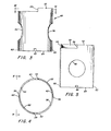
- Figure 1 is an elevational view partially in section of a preferred valve including various features of the invention.
- Figure 2 is a view of the preferred valve as seen along 2-2 in Figure 1.
- Figure 3 is a sectional view of the preferred reinforcing sleeve oriented in a manner similar to its orientation in Figure 1.
- Figure 4 is a view of the preferred sleeve as seen along line 4-4 of Figure 3.
- Figure 5 is an elevational view of the preferred sleeve as seen along line 5-5 of Figure 4.
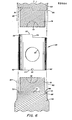
- Figure 6 is an exploded view partially in section of the preferred sleeve including its method of formation within a plastic valve body mold and various features of the invention.
- As seen in Figure 1, a
preferred valve 10 is primarily formed of plastic and includes avalve body 12 having a generally cylindricalmajor body portion 14 with an axially extendinginterior chamber 16. A pair offlow lines 18 of thebody 12 are preferably integrally formed with and intersect themajor body portion 14 and includeflow passages 20 thereof which intersect thechamber 16. A rotatable flow isolation member in the form of aplug 22 is mounted within thechamber 16 to be capable of being selectively positioned to allow or prevent flow through theflow passages 20. - Specifically, as seen in Figure 1, the
plug 22 includes atransverse opening 24 therethrough to allow flow through theflow passages 20 and opposingseats 26 which can be aligned with thepassages 20 when theplug 22 is rotated to prevent the flow of liquid therethrough. Theplug 22 includes ahandle 28 and at least one radially extendingrotational stop element 30 which will be discussed in detail hereinbelow. Further, thelower end 32 of theplug 22 includes a groove and retaining means 34 for preventing withdrawal of theplug 22 from thechamber 16 after it has been installed within themajor body portion 14. A sealedbottom 36 is added to themajor body portion 14 after installation of theplug 22 therein to prevent dirt or ice from forming at the bottom of thevalve 10 and interfering with the rotation of theplug 22. Thepreferred plug 22 is provided a plurality of O-ring seals 38 to primarily retain fluid within theflow passages 20 and thetransverse opening 24 of theplug 22 and prevent leakage at the top or bottom of theplug 22 during normal use of thevalve 10. A sealing ring 40 is also provided to the top of thevalve 10 to prevent the ingress of fluid or contanimates into thechamber 16 around the top of theplug 22. If "creep" were allowed to occur to thebody portion 14, proper sealing contact between the O-ring seals 38 andseats 26 and thechamber 16 could not be maintained and leakage through thevalve 10 and to the atmosphere could occur. - As seen in Figure 2, the
preferred plug 22 includes two radially extendingrotational stop elements 30 which are shown in a position for allowing flow through thevalve 10. Therotational stop elements 30 are prevented from rotation in a clockwise direction by respective abutting contact with theends 42 of a pair of axially extendingsectors 44 of themajor body portion 14. Rotation of theplug 22 in a counterclockwise direction would cause therotational stop elements 30 to make contact with theother ends 46 of the axially extendingsectors 44 of themajor body portion 14 to insure that theseats 26 are properly aligned with theflow passages 20 when thevalve 10 is closed. It should be noted that each of thesectors 44 extends less than ninety degrees to accommodate for the thickness of thestop elements 30 while allowing a full ninety degree rotation of theplug 22. Clearly, thesectors 44 andstop elements 30 might be oriented to any circumferential location around theplug 22 andbody portion 14 as long as the opening 24 andseats 26 will be properly alignable with theflow passages 20. It would also be obvious to alter thepreferred valve 10 to include only one stop element and one sector of approximately two hundred- seventy degrees for similar limitations on the rotation of the plug. - As thus described, the preferred valve is similar to the valve disclosed in U. S. Patent Nos. 4,014,513; 4,171,711; 4,324,011; and 4,488,741. Although the valves disclosed therein have been satisfactorily employed, the preferred
valve 10 includes features which could accommodate a higher pressure rating while being formed of a plastic material which is identical to that selected for the piping system in which it is to be employed. As mentioned hereinabove it has been found that when some plastic valves are subjected to higher operating pressures over an extended period of time, the body can experience "creep" where the design dimensions tend to change to interfere with the overall integrity of the plug as installed in the valve body and reduce the efficiency of the sealing of the valve. Accordingly, thepreferred valve 10 includes a preferredmajor body portion 14 which includes reinforcing means formed of a reinforcing material which is stronger than the plastic material. - The preferred reinforcing means is in the form of a
sleeve 48 which extends around themajor body portion 14. As best seen in Figures 3, 4, and 5, thepreferred sleeve 48 is formed of metal and is generally cylindrical to completely encircle themajor body portion 14. A pair ofopenings 50 are formed through thesleeve 48 and are to be aligned with theflow passages 20 of theflow lines 18. - Additionally, it will be noted that the
preferred sleeve 48 includes axially extendingportions 52 at the upper end thereof whichportions 52 will lie within the pair of axially extendingsectors 44 of thebody portion 14. As a result, theaxially extending portions 52 each include ends 54 which are aligned with theends 42 of thesectors 44 and ends 56 which are aligned with theends 46 of thesectors 44. As a result, with thesleeve 48 properly embedded within themajor body portion 14, thesleeve 48 will tend to reinforce themajor body portion 14 and further insure that there is adequate strength in theaxially extending sectors 44 for properly serving as a means to limit rotation of theplug 22 throughout the life of thevalve 10. In fact, it is significant that thesectors 44 be sufficiently stronger than thestop elements 30 to insure that thestop elements 30 will be cleanly severed from theplug 22 if one trys to force the rotation of theplug 22 by thesectors 44. It is better for the stop elements to be cleanly removed than to allow forced rotation of theplug 22 to result in its being directly damaged in a manner which would interfere with its ability to selectively control flow through the valve. - As shown in Figures 1 through 5, it should be clear that the
preferred sleeve 48 is at least partially encased within the plastic material of themajor body portion 14. In other words, thesleeve 48 will properly add reinforcement to themajor body portion 14 but will not generally be exposed to the environment or to the fluid within theflow passages 20 or theinterior chamber 16. Since it is not exposed to the fluid in thevalve 10, there is no need to be concerned with any leakage around thesleeve 48 which might otherwise occur. Further, since the preferred reinforcingsleeve 48 does not extend to the interior surface of theinterior chamber 16, thepreferred plug 22 will rotate and provide sealing as if it were installed within an entirely plasticmajor body portion 14. - As thus described, it is expected that the reinforcing
sleeve 48 will prevent creep which may otherwise have existed in themajor body portion 14. It is also expected that thesleeve 48 will be properly retained within themajor body portion 14 by the incasement of thesleeve 48 within the plastic material of themajor body portion 14. However, should there turn out to be some localized movement of the plastic material of themajor body portion 14, it would be possible to provide rounded edges for theopenings 50 to insure that no cracks or other failure of the plastic material develops at the edges of theholes 50. Additionally, although the sleeve 148 should remain in place since it is encased in the plastic material, an alternative configuration could include a plurality of radially extending holes at various locations around thesleeve 48 to cause the plastic material to flow therethrough when themajor body portion 14 is being formed. Since the plastic material may not directly adhere to the metal of thesleeve 48, the additional holes would further insure that there is a complete incasement of thesleeve 48 within the plastic material. With the plastic material extending through such a plurality of holes in thesleeve 48, thesleeve 48 would be further secured within themajor body portion 14 to resist any rotational forces created by thestop elements 30 during rotation of theplug 22. - To provide the
valve 10 with the included reinforcingsleeve 48, the preferred method of forming thevalve body 12 includes means for insuring that thesleeve 48 is properly supported and oriented during the plastic valve molding process. Specifically, as seen in Figure 6, abottom core 58 and atop core 60 of the basic valve body mold are utilized to properly support and orient thepreferred sleeve 48. Additional portions of the valve body mold have been eliminated from Figure 6 in order to be able to properly demonstrate those portions which are essential to an understanding of the overall method of forming thevalve body 12. For example, the valve body mold would preferably include a pair of passage cores for forming theflow passages 20 which passage cores would intersect with and join thebottom core 58 andtop core 60. Lastly, the valve body mold would primarily include an external mold which would be formed of two halves for the formation of the exterior of thevalve body 12. It should be understood that the injection molding of plastic material of the type used to form thepreferred valve body 12 is well known in the art. For example, if one were to provide any of the plastic valves mentioned as the prior art hereinabove, it would be quite common to inject plastic material into a valve body mold of the general type described and to allow the plastic material to set prior to disassembly of the mold and removal of the cores therefrom. - However, in order to specifically support and orient the
sleeve 48, thepreferred sleeve 48 includes four evenly-spacednotches 62 in thelower edge surface 64 thereof. Thebottom core 58 includes ashoulder 66 on an upwardly extendingcylindrical portion 68 thereof for receipt of thelower edge surface 64 of thesleeve 48 thereon. Theshoulder 66 has four evenly-spacedtabs 70 which are alignable with thenotches 62 for respectively receiving them thereon. Consequently, with thesleeve 48 installed on thecylindrical portion 68 of thebottom core 58, thesleeve 48 is concentrically positioned on thecore 58 and separated from acenter portion 72 thereof which is intended to partially form theinterior chamber 16. Further, because of the orientation of thenotches 62 and thetabs 70, thesleeve 48 can be positioned on thebottom core 58 with theopenings 50 properly aligned for the formation of the flow lines 18. - Once the
sleeve 48 is properly supported by thebottom core 58, thetop core 60 can be joined to thebottom core 58 as thecenter portion 74 thereof combines with thecenter portion 72 of thebottom core 58 to complete the form needed for theinterior chamber 16. The top core 6U includes circumferential recessed portions 76 for receipt of theaxially extending portions 52 of thesleeve 48 for the eventual formation of theaxially extending sectors 44 of thebody portion 14. - After the
bottom core 58 and thetop core 60 are joined in this manner with thesleeve 48 properly positioned therebetween, theopenings 50 of thesleeve 48 are aligned with a pair ofcavities 78 at opposite sides of the combinedcenter portions cavities 78 are intended to receive the interior end of the passage cores mentioned hereinabove. It should be clear that the passage cores could be formed as a single long core extending through thebottom core 58 and thetop core 60 so that thecavities 78 would alternatively extend all the way therethrough. In either case,sleeve 48 is aligned with the passage cores to allow the formation of theflow passages 20 of the flow lines 18. When the exterior halves of the valve body mold are fully installed, as generally represented by the dottedlines 80 to show their relationship to thecores major body portion 14 will be formed with an outside diameter larger than the exterior diameter of thesleeve 48. Accordingly, sufficient plastic material will be formed around the exterior of thesleeve 48 to primarily encase thesleeve 48 within the preferredmajor body portion 14. Since the passage core and the exterior halves of the valve body mold would not make any contact with thesleeve 48, thesleeve 48 would be surrounded by the plastic material at all locations other than those where there is direct contact with thecores sleeve 48 will be located radially within the cylindrical wall of themajor body portion 14 to include the plastic material internally and externally thereof. - It should be clear that, after the entire valve body mold is assembled, plastic material can be injected into the mold to at least partially surround the
sleeve 48. After the plastic material has been allowed to set and the exterior mold and interior cores are removed, thesleeve 48 will be retained within thevalve body 12. - Although the
preferred sleeve 48 is primarily intended to reinforce themajor body portion 14 throughout use of thevalve 10, it is possible that thesleeve 48 may provide an added benefit during formation of thebody portion 14. It has been found that when a body portion without an encased sleeve has been molded in the manner generally described hereinabove, it is not uncommon for the body portion to be slightly warped upon removal from the mold with the chamber thereof not having a truly cylindrical shape. As a result, the chamber must be machined to provide the required shape for proper receipt of a plug therein. Thesleeve 48 being employed in the method of formation of thebody portion 14 as described above could completely eliminate this required step and should, at the least, reduce the amount of machining that may be required. Further, if there is no need for such machining, it has been found that the interior surface of the chamber as formed by the body mold has excellent characteristics for direct installation of the plug therein. - Further, it would clearly be possible for various alterations to be made to the preferred embodiment described hereinabove without departing from the scope of the invention as claimed. For example, it might be advantageous to include only one notch at a lower edge surface of the sleeve to mate with only one tab on the bottom core to insure that there is only one possible orientation of the sleeve relative to the bottom core. Additionally, although the "bottom core" was used to primarily support the
sleeve 48 during the formation of thepreferred valve body 12, it would be possible for either a bottom or a top core to be properly configured for this purpose while still falling within the scope of the invention as claimed. - Although the method of providing the
preferred valve body 12 is expected to properly encase thesleeve 48 within the plastic material, it should be recognized that the bottom core or the top core could be slightly altered to further surround the end edges of thesleeve 48 with plastic material. As one example of any number of ways in which this could be accomplished, theshoulder 66 near each of the evenly spacedtabs 70 could be configured to discontinue a short distance from thetabs 70 to cause thelower edge surface 64 of thesleeve 48 to be separated from any portion of thebottom core 58. With the major circumference of thelower edge surface 64 being separated from any portion of thebottom core 58, the plastic material will primarily surround and encase the major circumference of thelower edge surface 64. Such a configuration would still fall within the scope of the invention as claimed since the sleeve would still include a generally radially extending surface which would be installed on a sleeve supporting surface of the valve body mold even though the supporting surface would be circumferentially smaller. - Still further, it should be clear that the
preferred sleeve 48 is simply one embodiment which could be utilized to practice the invention as claimed. Specifically, it would be possible for the reinforcingsleeve 48 to be made of some other material while still satisifying the basic criteria of reinforcing themajor body portion 14. Additionally, the sleeve need not be made to completely encircle themajor body portion 14 and could alternatively be made of some sheet material which could be formed to only partially encircle themajor body portion 14. For example, it might be desirable to form the reinforcing sleeve from some sheet metal and simply roll the pre-formed sheet material to only at least partially surround thechamber 16 above and below the flow lines 18. In fact, with some other type of means for supporting a reinforcing sleeve means during an alternative method of forming the major body portion, it would be possible for two separate partially encircling bands of metal to be installed within the interior of themajor body portion 14 to effectively prevent any circumferential expansion of themajor body portion 14 as might occur over an extended period of time at higher pressures. Although the figures do not show such upper and lower bands of reinforcing material separately in thevalve 10, they are shown in the form of corresponding upper and lower parts of thepreferred sleeve 48. Additionally, although it is clear from the cylindrical shape of the preferredmajor body portion 14 that it would be appropriate for thesleeve 48 to have a cylindrical shape, some other type of shape could be provided if such shape would still reinforce a major body portion of a similarly plastic valve. As a result, numerous alterations could clearly be made to the preferred embodiment described hereinabove without departing from the scope of the invention as claimed. - According to the provisions of the patent statutes, we have explained the principle, preferred construction and mode of operation of the invention and have illustrated and described what we now consider to represent its best embodiments. However, it should be understood that, within the scope of the appended claims, the invention may be practiced otherwise than as specifically illustrated and described.
- The embodiments of the invention in which an exclusive property or privilege is claimed are described as follows:
Claims (18)
Applications Claiming Priority (2)
| Application Number | Priority Date | Filing Date | Title |
|---|---|---|---|
| US74022885A | 1985-06-03 | 1985-06-03 | |
| US740228 | 1985-06-03 |
Publications (2)
| Publication Number | Publication Date |
|---|---|
| EP0208408A1 true EP0208408A1 (en) | 1987-01-14 |
| EP0208408B1 EP0208408B1 (en) | 1990-06-13 |
Family
ID=24975586
Family Applications (1)
| Application Number | Title | Priority Date | Filing Date |
|---|---|---|---|
| EP19860304194 Expired - Lifetime EP0208408B1 (en) | 1985-06-03 | 1986-06-03 | Reinforced plastic valve and method of forming it |
Country Status (4)
| Country | Link |
|---|---|
| EP (1) | EP0208408B1 (en) |
| JP (1) | JPH0637940B2 (en) |
| CA (1) | CA1291102C (en) |
| DE (1) | DE3671954D1 (en) |
Cited By (2)
| Publication number | Priority date | Publication date | Assignee | Title |
|---|---|---|---|---|
| EP0491203A1 (en) * | 1990-12-05 | 1992-06-24 | American Meter Holdings Corporation | Reinforced polymer valve |
| WO2016122599A1 (en) * | 2015-01-30 | 2016-08-04 | Hewlett-Packard Development Company, L.P. | Selection valves of fluid supply systems |
Families Citing this family (1)
| Publication number | Priority date | Publication date | Assignee | Title |
|---|---|---|---|---|
| JP5514863B2 (en) * | 2012-06-13 | 2014-06-04 | コヴィディエン・アクチェンゲゼルシャフト | Bronchial tracheal access valve for bronchial suction device |
Citations (5)
| Publication number | Priority date | Publication date | Assignee | Title |
|---|---|---|---|---|
| BE635934A (en) * | 1962-08-22 | |||
| US3092365A (en) * | 1960-06-23 | 1963-06-04 | Cherry Burrell Corp | Plug valve |
| US3314644A (en) * | 1964-04-21 | 1967-04-18 | Dwyer Mfg Co F W | Rotary flow control valve and method of manufacture |
| FR1555545A (en) * | 1967-06-30 | 1969-01-31 | ||
| US3825030A (en) * | 1973-03-20 | 1974-07-23 | Acf Ind Inc | Lined valves |
Family Cites Families (1)
| Publication number | Priority date | Publication date | Assignee | Title |
|---|---|---|---|---|
| JPS57101170A (en) * | 1980-12-16 | 1982-06-23 | Exxon Research Engineering Co | Cylinder valve |
-
1986
- 1986-05-26 CA CA 509950 patent/CA1291102C/en not_active Expired - Fee Related
- 1986-06-02 JP JP61127850A patent/JPH0637940B2/en not_active Expired - Lifetime
- 1986-06-03 EP EP19860304194 patent/EP0208408B1/en not_active Expired - Lifetime
- 1986-06-03 DE DE8686304194T patent/DE3671954D1/en not_active Expired - Lifetime
Patent Citations (5)
| Publication number | Priority date | Publication date | Assignee | Title |
|---|---|---|---|---|
| US3092365A (en) * | 1960-06-23 | 1963-06-04 | Cherry Burrell Corp | Plug valve |
| BE635934A (en) * | 1962-08-22 | |||
| US3314644A (en) * | 1964-04-21 | 1967-04-18 | Dwyer Mfg Co F W | Rotary flow control valve and method of manufacture |
| FR1555545A (en) * | 1967-06-30 | 1969-01-31 | ||
| US3825030A (en) * | 1973-03-20 | 1974-07-23 | Acf Ind Inc | Lined valves |
Cited By (6)
| Publication number | Priority date | Publication date | Assignee | Title |
|---|---|---|---|---|
| EP0491203A1 (en) * | 1990-12-05 | 1992-06-24 | American Meter Holdings Corporation | Reinforced polymer valve |
| WO2016122599A1 (en) * | 2015-01-30 | 2016-08-04 | Hewlett-Packard Development Company, L.P. | Selection valves of fluid supply systems |
| CN107206803A (en) * | 2015-01-30 | 2017-09-26 | 惠普发展公司,有限责任合伙企业 | The selector valve of fluid feed system |
| EP3250385A4 (en) * | 2015-01-30 | 2018-09-26 | Hewlett-Packard Development Company, L.P. | Selection valves of fluid supply systems |
| US10272690B2 (en) | 2015-01-30 | 2019-04-30 | Hewlett-Packard Development Company, L.P. | Selection valves of fluid supply systems |
| CN107206803B (en) * | 2015-01-30 | 2019-07-19 | 惠普发展公司,有限责任合伙企业 | The selector valve of fluid feed system |
Also Published As
| Publication number | Publication date |
|---|---|
| EP0208408B1 (en) | 1990-06-13 |
| JPH0637940B2 (en) | 1994-05-18 |
| DE3671954D1 (en) | 1990-07-19 |
| JPS61290278A (en) | 1986-12-20 |
| CA1291102C (en) | 1991-10-22 |
Similar Documents
| Publication | Publication Date | Title |
|---|---|---|
| US4511120A (en) | Plastic service valve | |
| US4988077A (en) | Reinforced plastic valve | |
| EP0757766B1 (en) | Butterfly valve assembly and method of manufacture | |
| US4348006A (en) | Plastic valve assembly | |
| US4572239A (en) | High pressure ball valve | |
| US3241806A (en) | Disc valve having plastic layer on resilient seating surface | |
| US4479513A (en) | High pressure ball valve | |
| US4685611A (en) | Butterfly valve construction having a composite seat | |
| US3662778A (en) | Gate valve structure | |
| US3990675A (en) | Butterfly valve | |
| US4257575A (en) | Rotary ball valve having seating rings | |
| US3306316A (en) | Disc valve and fitting | |
| US4465260A (en) | Plastic valve and improved actuator therefor | |
| US3376015A (en) | High pressure disc valve | |
| US3095177A (en) | Valve assembly and seal forming means for the same | |
| EP0491203B1 (en) | Reinforced polymer valve | |
| US5154396A (en) | Reinforced plastic valve | |
| US5100103A (en) | Reinforced plastic valve | |
| US4778152A (en) | Plug valve havig interchangeable plug member | |
| EP0023133B1 (en) | Plastics butterfly valve | |
| US3782684A (en) | Seat insert for butterfly-type valves | |
| EP0144651B1 (en) | Ball valve and method of manufacturing the same | |
| CA1094530A (en) | Resilient seated gate valve | |
| US3843091A (en) | Ball valve for high temperatures | |
| EP0208408A1 (en) | Reinforced plastic valve and method of forming it |
Legal Events
| Date | Code | Title | Description |
|---|---|---|---|
| PUAI | Public reference made under article 153(3) epc to a published international application that has entered the european phase |
Free format text: ORIGINAL CODE: 0009012 |
|
| AK | Designated contracting states |
Kind code of ref document: A1 Designated state(s): AT BE CH DE FR GB IT LI LU NL SE |
|
| RBV | Designated contracting states (corrected) |
Designated state(s): DE FR GB IT |
|
| 17P | Request for examination filed |
Effective date: 19870606 |
|
| 17Q | First examination report despatched |
Effective date: 19880801 |
|
| GRAA | (expected) grant |
Free format text: ORIGINAL CODE: 0009210 |
|
| AK | Designated contracting states |
Kind code of ref document: B1 Designated state(s): DE FR GB IT |
|
| REF | Corresponds to: |
Ref document number: 3671954 Country of ref document: DE Date of ref document: 19900719 |
|
| ITF | It: translation for a ep patent filed |
Owner name: JACOBACCI & PERANI S.P.A. |
|
| ET | Fr: translation filed | ||
| PLBE | No opposition filed within time limit |
Free format text: ORIGINAL CODE: 0009261 |
|
| STAA | Information on the status of an ep patent application or granted ep patent |
Free format text: STATUS: NO OPPOSITION FILED WITHIN TIME LIMIT |
|
| 26N | No opposition filed | ||
| ITTA | It: last paid annual fee | ||
| PGFP | Annual fee paid to national office [announced via postgrant information from national office to epo] |
Ref country code: FR Payment date: 19940525 Year of fee payment: 9 |
|
| PGFP | Annual fee paid to national office [announced via postgrant information from national office to epo] |
Ref country code: GB Payment date: 19940531 Year of fee payment: 9 |
|
| PGFP | Annual fee paid to national office [announced via postgrant information from national office to epo] |
Ref country code: DE Payment date: 19940812 Year of fee payment: 9 |
|
| PG25 | Lapsed in a contracting state [announced via postgrant information from national office to epo] |
Ref country code: GB Effective date: 19950603 |
|
| GBPC | Gb: european patent ceased through non-payment of renewal fee |
Effective date: 19950603 |
|
| PG25 | Lapsed in a contracting state [announced via postgrant information from national office to epo] |
Ref country code: FR Effective date: 19960229 |
|
| PG25 | Lapsed in a contracting state [announced via postgrant information from national office to epo] |
Ref country code: DE Effective date: 19960301 |
|
| REG | Reference to a national code |
Ref country code: FR Ref legal event code: ST |
|
| PG25 | Lapsed in a contracting state [announced via postgrant information from national office to epo] |
Ref country code: IT Free format text: LAPSE BECAUSE OF NON-PAYMENT OF DUE FEES;WARNING: LAPSES OF ITALIAN PATENTS WITH EFFECTIVE DATE BEFORE 2007 MAY HAVE OCCURRED AT ANY TIME BEFORE 2007. THE CORRECT EFFECTIVE DATE MAY BE DIFFERENT FROM THE ONE RECORDED. Effective date: 20050603 |