EP0207903B1 - A breadmaking method for the production of crisp long term preservation small loaves, and a system therefor - Google Patents
A breadmaking method for the production of crisp long term preservation small loaves, and a system therefor Download PDFInfo
- Publication number
- EP0207903B1 EP0207903B1 EP86830182A EP86830182A EP0207903B1 EP 0207903 B1 EP0207903 B1 EP 0207903B1 EP 86830182 A EP86830182 A EP 86830182A EP 86830182 A EP86830182 A EP 86830182A EP 0207903 B1 EP0207903 B1 EP 0207903B1
- Authority
- EP
- European Patent Office
- Prior art keywords
- rollers
- dough
- nip
- working area
- conveyor
- Prior art date
- Legal status (The legal status is an assumption and is not a legal conclusion. Google has not performed a legal analysis and makes no representation as to the accuracy of the status listed.)
- Expired - Lifetime
Links
Images


Classifications
-
- A—HUMAN NECESSITIES
- A21—BAKING; EDIBLE DOUGHS
- A21D—TREATMENT OF FLOUR OR DOUGH FOR BAKING, e.g. BY ADDITION OF MATERIALS; BAKING; BAKERY PRODUCTS
- A21D2/00—Treatment of flour or dough by adding materials thereto before or during baking
- A21D2/08—Treatment of flour or dough by adding materials thereto before or during baking by adding organic substances
- A21D2/24—Organic nitrogen compounds
- A21D2/26—Proteins
- A21D2/264—Vegetable proteins
- A21D2/265—Vegetable proteins from cereals, flour, bran
-
- A—HUMAN NECESSITIES
- A21—BAKING; EDIBLE DOUGHS
- A21C—MACHINES OR EQUIPMENT FOR MAKING OR PROCESSING DOUGHS; HANDLING BAKED ARTICLES MADE FROM DOUGH
- A21C3/00—Machines or apparatus for shaping batches of dough before subdivision
- A21C3/06—Machines for coiling sheets of dough, e.g. for producing rolls
-
- A—HUMAN NECESSITIES
- A21—BAKING; EDIBLE DOUGHS
- A21C—MACHINES OR EQUIPMENT FOR MAKING OR PROCESSING DOUGHS; HANDLING BAKED ARTICLES MADE FROM DOUGH
- A21C9/00—Other apparatus for handling dough or dough pieces
- A21C9/08—Depositing, arranging and conveying apparatus for handling pieces, e.g. sheets of dough
- A21C9/088—Folding or bending discrete dough pieces or dough strips
Definitions
- This invention relates to a breadmaking method for producing crisp, long term preservation, buns on an industrial scale.
- the structure of bread so made is generally characterized by a dense outer crust and a fine cellular underlayer and a soft elastic inner crumb of a more or less pronounced character which is unevenly distributed.
- EP-A-0115108 describes a frozen dough composition comprising wheat protein in an amount greater than 16% based on the total weight of flour.
- composition however, requires at the same time also a high content of 50 to 95% water.
- the present invention uses a water content lower than 40%. This content is essential in order to permit the hard working after the first proofing of the mix.
- US-A-4046920 describes a method for forming pizza pie shells in a continuously transported web of dough, using the steps of proofing the moving web, forming dough shells, resting the shells and reclaiming and blending the trimmings.
- the dough however does not undergo a compression under viscous conditions after the first proofing step, the forming apparatus produces trimmings and a water content of 50% moisture is typically required.
- the problem underlying this invention is, therefore, that of providing a novel breadmaking method whereby it becomes possible to produce on an industrial scale buns which can retain all the characteristics of fresh bread over time, and specifically its flavour, fragrance, and crispness.
- This solution is realized by a process for making a crisp, crumbless long preservation bread from a dough mix wherein flat blanks are produced, rolled up, proofed and baked to buns, characterised in that said flat blanks are produced by the steps of:
- the kneading operation was conducted in two stages separated by a rest period of about 6 hours (two-stage dough).
- the resulting dough was particularly consistent, and was then subjected to a series of successive rolling steps on a rolling machine until it yielded a homogeneous strip of breadmaking dough (of the so-called "hard dough” type), exhibiting visco-elastic characteristics and being 25 mm thick.
- the breadmaking dough thus obtained has a specific density of 1.05 kg/dm 3 .
- the breadmaking dough strip was then fed into the nip of two parallel rollers driven rotatively at a peripheral velocity of 0.19 m/sec and held in tangential contact along a common generating line.
- One of those rollers had plural molding cavities of triangular shape formed in its outer sleeve which have an average depth of 4 mm, the other roller having a smooth outer sleeve.
- the flat blank was then rolled up and allowed to leaven to a 45% swell by volume.
- the leavened product was then baked at a temperature of about 250 to 270 degrees centigrade to yield a sample bun of a rich brown color which was both consistent and crisp.
- the sample bun was then dried to a moisture content of 5%, and on breaking, it showed a fine cellular and homogeneously dispersed structure.
- a system for producing crisp buns on an industrial scale comprises a kneading machine, a rolling machine, a forming machine, a leavening chamber, a baking oven, and a drier, in that order.
- the forming machine 1 comprises, in turn, a molding station 2, a wetting station 3, and a final forming station 4, in that order.
- a breadmaking dough being processed will move through the above mentioned machines in the order indicated.
- the molding station 2 comprises a feeder assembly 5 composed of a frame 5c which carries rotatably a plurality of power driven roller pairs 5a, 5b with parallel axes.
- a gap is defined between each roller pair 5a, 5b wherethrough a breadmaking dough 6 is made to pass.
- the dough 6 reaches the feeder assembly 5 in the form of plural breadmaking dough strips (eight strips in the example shown) and goes sequentially through the nips of all the roller pairs 5a, 5b.
- the size of said gap, for adjoining roller pairs, decreases in the direction of advance of the dough 6 as indicated by the arrow A.
- rollers Downstream of the feeder assembly 5, there are a pair of rollers, respectively a die roller 7 and a backup roller 8, lying parallel to each other and to the rollers 5a, 5b and being driven counter- rotatingly by motors, not shown.
- rollers 7 and 8 are journalled on a pair of shoulders 13 of a framework 10 by means of respective seals 11 and 12.
- the seals 12 are supported slidingly within respective seats 13a formed in the shoulders 13.
- Respective screw registers 14,14a are mounted on each shoulder 13 and connected to their corresponding seal 12 to adjust its position relatively to the seal 11, and change, if desired, the distance between rollers 7 and 8.
- the screw registers 14, 14a form a means of positioning the roller 8 relatively to the roller 7; such means are essentially provided to position said rollers in mutual contact relationship along a common generating line B.
- the roller 7 has a plurality of molding cavities 15, hereinafter referred to as the "molds”, which are distributed regularly across its outer sleeve on cylindrical segments.
- the number of the molds 15 which are aligned along any generating line of the roller 7 is equal to the number of the strips of dough 6 oncoming to the feeder assembly 5.
- the molds 15 have a substantially triangular shape with rounded off apexes, and have their bottoms partially coated with an adhesion-preventing material, such as an epoxy resin.
- the roller 8 has a smooth outer sleeve and doctoring members 16 are active thereon, one for each cylindrical segment of molds 15.
- the doctoring members 16 are carried on a shaft 17 which extends between the shoulders 13 and have a blade 16a set to the sleeve of the roller 8 directly downstream of the generating line B.
- the molding station 2 further comprises a carpet conveyor 20 trained in a closed loop around respective rollers 21, and having one end held close to the roller 7 by a nose 22.
- the carpet 20 has a working conveying surface 23.
- a levelling roller 24 is supported idly between the shoulders 13 downstream of the rollers 7, 8 and above the working surface 23; the roller 24 is rubber foam lined.
- the wetting 3 and final forming 4 stations are both carried on a frame 28 extending mainly in a longitudinal direction and being provided with a pair of longitudinal bars 28a and 28b which are provided, in turn, with legs 29. To the legs 29, at a region underlying the longitudinal bars 28a, 28b, there is also connected a pan 27 for collecting any scrap dough.
- the wetting station 3 comprises, downstream of the carpet 20, a number of mesh conveyors 31 equal in number to molds 15 aligned along any generating line of the roller 7, and moving in the same direction as the carpet 20 and fanning out in the direction of the arrow A.
- the product travelling on the mesh conveyors 31 is subjected to water spray jets which are delivered at a preset rate from spray members indicated diagramatically at 21 a.
- the final forming station 4 comprises a carpet conveyor 30 having a working area 32 on the same plane as the mesh conveyors 31.
- the carpet 30 is stretched between rollers 30a and 30b journalled on the longitudinal bars 28a and 28b.
- a gap is defined between the rollers 33 which has a set width to let said product being processed therethrough.
- rollers 33 are also journalled on the longitudinal bars 28a and 28b.
- a portion of the working area 32 of the carpet conveyor 30 is acted upon by a roll-up device 35.
- the device 35 comprises a frame 36 extending across the direction (A) of advance of the product being processed and being fastened to the longitudinal bars 28a, 28b at a region overlying the carpet 30.
- a plurality of clamps 37 extending vertically to the working area 32 of the carpet 30 are hooked on the frame 36 which are provided in the proximity of the working area with respective pads 37a of felt or the like comparatively soft material having a high frictional coefficient.
- the pads 37a are spring mounted to their respective clamps 37.
- the station 4 further comprises a folding device 40 having a slide 41 movable along runways 42, in turn made fast with the longitudinal bars 28a, 28b.
- the slide 41 has a crosspiece 43 which extends bridge-fashion over the working area of the carpet conveyor 30.
- Mounted on the crosspiece 43 are a plurality of fluid-operated cylinders 44 each having a piston rod 45 which extends in a perpendicular direction to the working area 32 of the carpet 30 and a corresponding plurality of C-brackets 46 located between the crosspiece 43 and said working area 32.
- the brackets 46 have a bore 47 where through the corresponding piston rod 45 is guided. Said brackets 46 are effective to prevent, with the piston rod 45 raised, the product being processed from sticking to the piston rod.
- the slide 41 is reciprocated in a parallel direction to the arrow A by a connecting rod-crank lever type of linkage generally indicated at 50.
- the piston rods 45 are drawn up, by respective cylinders 44 forming drive means therefor, to a raised position toward the crosspiece 43 each time that the movement of the slide 41 takes place in the opposite direction to the advancing product being processed, and are extended out, with their free ends brought close to the carpet 30 on said movement taking place in the same direction as the arrow A.
- the piston rods 45 perform, therefore, with respect to the frame 28, a rectangular cycle movement in a perpendicular plane to the working area of the carpet 30 in parallel with the arrow A.
- the travel path of the rods 45 down toward the carpet 30 will be referred to as the "active path”.
- the folding device 40 further comprises a corresponding plurality of pairs of juxtaposed templates 51, each pair delimiting a passageway located along the active path of the corresponding piston rod 45.
- the template pairs 51 are mounted stationary on the frame 28 and have confronting surfaces 52 which are curved and concave in a symmetrical arrangement with respect to the plane wherein the corresponding piston rod moves.
- Each template pair 51 overlies, over at least some distance, a corresponding conveyor belt 54 provided for transporting the product to the leavening chamber and then to the baking oven.
- the ingredients are kneaded in two stages, that is two distinct kneading sub-steps separated by a rest period, using high gluten content (protein content of about 13-14%) flour, water in the amount of about 35-37 % bulk based on the dry flour, yeast, olive oil, malt, and salt bulk.
- high gluten content protein content of about 13-14%) flour
- water in the amount of about 35-37 % bulk based on the dry flour
- yeast olive oil, malt, and salt bulk.
- the resulting dough is subjected to sequential rolling passes until a homogeneous breadmaking dough web is obtained which has visco-elastic characteristics.
- the dough sheet is then fed into a rolling machine where roller pairs will roll it into sheets of decreasing thickness.
- the last roller pair in the rolling machine will split the rolled dough into plural strips 6, as shown in the drawings.
- the breadmaking dough strips are then taken to the feeder assembly 5, wherein they undergo additional thickness reduction by rollers 5a, 5b. For each dough strip there corresponds, as mentioned previously, one cylindrical segment having molds 15 in the die roller 7.
- the speed of the roller pairs 5a, 5b is constant over time, and accordingly the amount of the dough which is being fed into the nip of the rollers 7 and 8, is also constant, while drawing of dough into any mold 15 of the roller 7 would by cyclic and dependent on an empty mold moving past the feeder 5.
- each dough strip 6 upstream of the rollers 7 and 8 will be subjected to an intermittent forward movement at the same rate as the respective molds 15 moving past.
- the dough is forced to flow visco-elastically to almost completely fill the cavity of the mold 15 while contributing, on account of its consistency and toughness, a significant elastic reaction force, to deliver, downstream of the generating line B and for each mold 15, a compressed flat blank 60.
- rollers 7, 8 820 mm long and having an outside diameter of 270 mm, with eight mold cavities 15 aligned on one generating line, are subjected in operation to a load in the region of 15 to 30 tons.
- the blanks 60 undergo, directly downstream of the generating line B, a slight amount of elastic recovery which results in their becoming detached from the respective molds.
- the blanks 60 are then laid onto the carpet conveyor 20 and rolled out thereover by the levelling roller 24.
- each blank Downstream of the rollers 33, each blank will have a leading portion (in the direction of the arrow A) which curls slightly upward to invite subsequent rolling up at the device 35.
- the blanks 60 entrained by the carpet 30 are rolled up into a substantially cylindrical configuration indicated at 61 in the drawings.
- the cylindrical blanks 61 are taken forward by the carpet 30 toward the templates 51 of the folding device 40.
- each blank 61 will be reached by the piston rod 45 of its corresponding fluid-operated cylinder '44, taken by the slide 41 in the opposite direction to the advancing direction of the carpet 30.
- Each piston rod 45 is lowered onto the carpet 30 directly upstream of a corresponding blank 61 and follows it in its path of travel up to the templates 51, to force it through the gap between the confronting surfaces 52 of the latter.
- the blanks 61 will be bent into a crescent-like shape as indicated at 62 in the drawing.
- the leavened blanks are then baked at a temperature in the 250° to 270°C range.
Landscapes
- Life Sciences & Earth Sciences (AREA)
- Engineering & Computer Science (AREA)
- Food Science & Technology (AREA)
- Bakery Products And Manufacturing Methods Therefor (AREA)
- Holo Graphy (AREA)
- Medicines Containing Plant Substances (AREA)
- Noodles (AREA)
- Seeds, Soups, And Other Foods (AREA)
- Confectionery (AREA)
Abstract
Description
- This invention relates to a breadmaking method for producing crisp, long term preservation, buns on an industrial scale.
- There exists a demand for a bread which can retain enhanced fragrant and crisp properties over time.
- Current techniques for making bread from a dough composed of water, flour, and yeast, may be reduced to the following cycle: dough is first made as homogeneous as possible through successive mechanical processing, allowed to leaven, cut into pieces providing a blank which is fashioned into desired forms, after which, following as a rule further leavening, the bread forms are baked.
- The structure of bread so made is generally characterized by a dense outer crust and a fine cellular underlayer and a soft elastic inner crumb of a more or less pronounced character which is unevenly distributed.
- However, it is a well known fact that traditional bread undergoes, after a more or less short time period, a series of structural and organoleptic changes leading to its first becoming stale and then dry.
- Bread crumb in particular is liable to undergo such structural alterations and progressively lose its elastic character to become coarse and abrasive, and therefore unpalatable.
- Other prior techniques for processing flour- based doughs yield bread-substitutive products, mainly crackers and bread sticks, which notoriously preserve well for a relatively long time. It should be noted, however, that such substitutes have none of the fragrant and appetizing qualities of fresh bread.
- Thus, such products fail to meet the above- mentioned demand.
- EP-A-0115108 describes a frozen dough composition comprising wheat protein in an amount greater than 16% based on the total weight of flour.
- This composition, however, requires at the same time also a high content of 50 to 95% water. The present invention uses a water content lower than 40%. This content is essential in order to permit the hard working after the first proofing of the mix.
- US-A-4046920 describes a method for forming pizza pie shells in a continuously transported web of dough, using the steps of proofing the moving web, forming dough shells, resting the shells and reclaiming and blending the trimmings. The dough however does not undergo a compression under viscous conditions after the first proofing step, the forming apparatus produces trimmings and a water content of 50% moisture is typically required.
- The problem underlying this invention is, therefore, that of providing a novel breadmaking method whereby it becomes possible to produce on an industrial scale buns which can retain all the characteristics of fresh bread over time, and specifically its flavour, fragrance, and crispness.
- Broadly a solution for this problem is the one of dealing with breadmaking dough, directly downstream of its preparation, to modify its chemical and physical state through violent mechanical treatments whereby baking will yield a bun the whole structure whereof is similar to the crust of traditional bread, being finely cellular and evenly distributed.
- This solution is realized by a process for making a crisp, crumbless long preservation bread from a dough mix wherein flat blanks are produced, rolled up, proofed and baked to buns, characterised in that said flat blanks are produced by the steps of:
- providing a dough mix having yeast added thereto and having a wheat flour with a gluten content higher than 12% and an amount of water lower then 40% based on flour bulk;
- kneading and rolling the dough to form a homogeneous breadmaking dough web or strip, which has visco-elastic charcteristics;
- feeding metered strips of said dough web or strip at a constant speed to the nip of a pair of rollers, at least one of said rollers having an array of mold cavities facing a smooth surface of the other roller at the nip of the rollers;
- maintaining said rollers such that, during the feeding of said strip of dough, there is no gap between the rollers except at said mold cavities;
- rotating said rollers with a peripheral direction, at the nip thereof, converging to the direction of feeding of said strips, so that an amount of dough accumulates at the nip of the rollers;
- controlling the rotational speed of the rollers and the feeding speed of the metered strips so that the volume of dough supplied to the rollers is substantially equal to the volume of said mold cavities, and so that said amount of dough becomes subjected to a violent compression and is forced into said cavities at the nip of said rollers; and
- removing the compressed dough in the form of sheetlike blanks from said cavities beyond said nip.
- While this method runs counter to traditional breadmaking techniques, which all observe a common criterion of avoiding, as far as possible, any violent mechanical handling of the breadmaking dough downstream of the rolling step in order to minimize disturbance of the leavening process, it has been found in actual practice that the resulting product was stable over time from both a chemical and physical standpoint and an organoleptic standpoint, and accordingly, adapted for long term storage without alteration of its initial properties of fragrance and crispness.
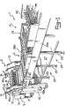
- Figure 1 is a fragmentary perspective view of an industrial breadmaking apparatus for producing long term preservation crisp buns;
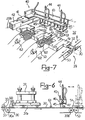
- figure 2 is a top plan view of a portion of the breadmaking apparatus of figure I;
- figure 3 is a longitudinal section view taken along line 3-3 of figure 2;
- figure 4 is a fragmentary perspective view of a pressure molding station for compressed flat bun blanks and comprising a portion of the breadmaking apparatus of figure 1;
- figure 5 is a section view taken along line 5-5 of figure 4;
- figure 6 is a diagrammatic elevational view, partially in section showing a bun forming station of the breadmaking apparatus of figure I; and
- figure 7 is a detailed perspective view of one portion of the bun forming station of figure 6.
- An illustrative and not limitative example will be described herein below of an application of the inventive method.
- To prepare a breadmaking dough, the following ingredients were used:
- 100 kg flour having a protein content of about 13% by weight, which when analyzed by the Chopin Method, gave the following index values: W = 260, P/L = 0.5;
- 35 kg water;
- 3 kg breadmaking yeast.
- To the mixture were added 5 kg olive oil, sodium chloride, and malt in conventional dosages.
- The kneading operation was conducted in two stages separated by a rest period of about 6 hours (two-stage dough).
- The resulting dough was particularly consistent, and was then subjected to a series of successive rolling steps on a rolling machine until it yielded a homogeneous strip of breadmaking dough (of the so-called "hard dough" type), exhibiting visco-elastic characteristics and being 25 mm thick.
- The breadmaking dough thus obtained has a specific density of 1.05 kg/dm3.
- The breadmaking dough strip was then fed into the nip of two parallel rollers driven rotatively at a peripheral velocity of 0.19 m/sec and held in tangential contact along a common generating line.
- One of those rollers had plural molding cavities of triangular shape formed in its outer sleeve which have an average depth of 4 mm, the other roller having a smooth outer sleeve.
- Dough would only be passed between the rollers where an empty mold is present directly upstream of the contact generating line therebetween.
- It has been found that in going through the roller nip, the dough underwent a high and rapid compression causing it to flow viscoelastically to almost completely fill a respective molding cavity. Downstream of the rollers, a compressed flat blank was obtained that was made easier to shake out of the mold cavity by the elastic recovery tendency of breadmaking dough.
- The flat blank was then rolled up and allowed to leaven to a 45% swell by volume.
- The leavened product was then baked at a temperature of about 250 to 270 degrees centigrade to yield a sample bun of a rich brown color which was both consistent and crisp.
- The sample bun was then dried to a moisture content of 5%, and on breaking, it showed a fine cellular and homogeneously dispersed structure.
- 20 days later, the sample buns so obtained showed no significant changes in consistency, flavour, fragrance, and crispness.
- In the course of further tests, it was found that best results are to be obtained by using high gluten content flours (with a protein content of no less than 12%).
- By way of non-limitative example, a system will be now described for producing crisp buns on an industrial scale, which is particularly suitable to implement the inventive method.
- A system for producing crisp buns on an industrial scale comprises a kneading machine, a rolling machine, a forming machine, a leavening chamber, a baking oven, and a drier, in that order.
- In the accompanying drawings, only the forming machine, comprehensively designated 1, is shown, the remaining machines being omitted because quite conventional.
- The forming machine 1 comprises, in turn, a molding station 2, a wetting station 3, and a final forming station 4, in that order.
- A breadmaking dough being processed will move through the above mentioned machines in the order indicated.
- The molding station 2 comprises a feeder assembly 5 composed of a
frame 5c which carries rotatably a plurality of power drivenroller pairs - A gap is defined between each
roller pair breadmaking dough 6 is made to pass. - The
dough 6 reaches the feeder assembly 5 in the form of plural breadmaking dough strips (eight strips in the example shown) and goes sequentially through the nips of all theroller pairs - The size of said gap, for adjoining roller pairs, decreases in the direction of advance of the
dough 6 as indicated by the arrow A. - Downstream of the feeder assembly 5, there are a pair of rollers, respectively a
die roller 7 and abackup roller 8, lying parallel to each other and to therollers - The
rollers shoulders 13 of aframework 10 by means ofrespective seals 11 and 12. - The
seals 12 are supported slidingly withinrespective seats 13a formed in theshoulders 13. - Respective screw registers 14,14a are mounted on each
shoulder 13 and connected to theircorresponding seal 12 to adjust its position relatively to the seal 11, and change, if desired, the distance betweenrollers - The screw registers 14, 14a form a means of positioning the
roller 8 relatively to theroller 7; such means are essentially provided to position said rollers in mutual contact relationship along a common generating line B. - The
roller 7 has a plurality ofmolding cavities 15, hereinafter referred to as the "molds", which are distributed regularly across its outer sleeve on cylindrical segments. The number of themolds 15 which are aligned along any generating line of theroller 7 is equal to the number of the strips ofdough 6 oncoming to the feeder assembly 5. - The
molds 15 have a substantially triangular shape with rounded off apexes, and have their bottoms partially coated with an adhesion-preventing material, such as an epoxy resin. - The
roller 8 has a smooth outer sleeve and doctoringmembers 16 are active thereon, one for each cylindrical segment ofmolds 15. The doctoringmembers 16 are carried on ashaft 17 which extends between theshoulders 13 and have ablade 16a set to the sleeve of theroller 8 directly downstream of the generating line B. - The molding station 2 further comprises a
carpet conveyor 20 trained in a closed loop aroundrespective rollers 21, and having one end held close to theroller 7 by anose 22. Thecarpet 20 has a working conveyingsurface 23. - A levelling
roller 24 is supported idly between theshoulders 13 downstream of therollers surface 23; theroller 24 is rubber foam lined. - The wetting 3 and final forming 4 stations are both carried on a
frame 28 extending mainly in a longitudinal direction and being provided with a pair oflongitudinal bars legs 29. To thelegs 29, at a region underlying thelongitudinal bars pan 27 for collecting any scrap dough. - The wetting station 3 comprises, downstream of the
carpet 20, a number ofmesh conveyors 31 equal in number tomolds 15 aligned along any generating line of theroller 7, and moving in the same direction as thecarpet 20 and fanning out in the direction of the arrow A. - The product travelling on the
mesh conveyors 31 is subjected to water spray jets which are delivered at a preset rate from spray members indicated diagramatically at 21 a. - The final forming station 4 comprises a
carpet conveyor 30 having a workingarea 32 on the same plane as themesh conveyors 31. - The
carpet 30 is stretched betweenrollers longitudinal bars - Between the
mesh 31 andcarpet 30 conveyors there intervene a pair ofrollers 33, in parallel stacked relationship, which are powered and laid across the direction of advance of the product being processed (arrow A). - A gap is defined between the
rollers 33 which has a set width to let said product being processed therethrough. - The
rollers 33 are also journalled on thelongitudinal bars - Directly downstream of the
rollers 33, a portion of the workingarea 32 of thecarpet conveyor 30 is acted upon by a roll-updevice 35. - The
device 35 comprises aframe 36 extending across the direction (A) of advance of the product being processed and being fastened to thelongitudinal bars carpet 30. - A plurality of
clamps 37 extending vertically to the workingarea 32 of thecarpet 30 are hooked on theframe 36 which are provided in the proximity of the working area withrespective pads 37a of felt or the like comparatively soft material having a high frictional coefficient. - The
pads 37a are spring mounted to theirrespective clamps 37. - The station 4 further comprises a
folding device 40 having aslide 41 movable alongrunways 42, in turn made fast with thelongitudinal bars - The
slide 41 has acrosspiece 43 which extends bridge-fashion over the working area of thecarpet conveyor 30. Mounted on thecrosspiece 43 are a plurality of fluid-operatedcylinders 44 each having apiston rod 45 which extends in a perpendicular direction to the workingarea 32 of thecarpet 30 and a corresponding plurality of C-brackets 46 located between the crosspiece 43 and said workingarea 32. Thebrackets 46 have abore 47 where through thecorresponding piston rod 45 is guided. Saidbrackets 46 are effective to prevent, with thepiston rod 45 raised, the product being processed from sticking to the piston rod. - The
slide 41 is reciprocated in a parallel direction to the arrow A by a connecting rod-crank lever type of linkage generally indicated at 50. - The
piston rods 45 are drawn up, byrespective cylinders 44 forming drive means therefor, to a raised position toward thecrosspiece 43 each time that the movement of theslide 41 takes place in the opposite direction to the advancing product being processed, and are extended out, with their free ends brought close to thecarpet 30 on said movement taking place in the same direction as the arrow A. - The
piston rods 45 perform, therefore, with respect to theframe 28, a rectangular cycle movement in a perpendicular plane to the working area of thecarpet 30 in parallel with the arrow A. - Of that cyclic movement, the travel path of the
rods 45 down toward thecarpet 30 will be referred to as the "active path". - The
folding device 40 further comprises a corresponding plurality of pairs of juxtaposedtemplates 51, each pair delimiting a passageway located along the active path of thecorresponding piston rod 45. - The template pairs 51 are mounted stationary on the
frame 28 and have confrontingsurfaces 52 which are curved and concave in a symmetrical arrangement with respect to the plane wherein the corresponding piston rod moves. - Each
template pair 51 overlies, over at least some distance, a correspondingconveyor belt 54 provided for transporting the product to the leavening chamber and then to the baking oven. - The production steps for crisp buns made with the inventive method will be now described in connection with the system just described.
- The ingredients are kneaded in two stages, that is two distinct kneading sub-steps separated by a rest period, using high gluten content (protein content of about 13-14%) flour, water in the amount of about 35-37 % bulk based on the dry flour, yeast, olive oil, malt, and salt bulk.
- The resulting dough is subjected to sequential rolling passes until a homogeneous breadmaking dough web is obtained which has visco-elastic characteristics.
- The dough sheet is then fed into a rolling machine where roller pairs will roll it into sheets of decreasing thickness.
- The last roller pair in the rolling machine will split the rolled dough into
plural strips 6, as shown in the drawings. - The breadmaking dough strips are then taken to the feeder assembly 5, wherein they undergo additional thickness reduction by
rollers segment having molds 15 in thedie roller 7. - The speed of the roller pairs 5a, 5b is constant over time, and accordingly the amount of the dough which is being fed into the nip of the
rollers mold 15 of theroller 7 would by cyclic and dependent on an empty mold moving past the feeder 5. - Thus, each
dough strip 6 upstream of therollers respective molds 15 moving past. - During the wait for a fresh
empty mold 15, thedough 6 undergoes a consequent slight build-up upstream of therollers - When a
mold 15 is present directly upstream of the generating line B of contact of therollers mold 15 cavity. - The dough is forced to flow visco-elastically to almost completely fill the cavity of the
mold 15 while contributing, on account of its consistency and toughness, a significant elastic reaction force, to deliver, downstream of the generating line B and for eachmold 15, a compressed flat blank 60. - By way of illustration, it has been found that
rollers mold cavities 15 aligned on one generating line, are subjected in operation to a load in the region of 15 to 30 tons. - The
blanks 60 undergo, directly downstream of the generating line B, a slight amount of elastic recovery which results in their becoming detached from the respective molds. - Any
blanks 60 sticking to thebackup roller 8 would be removed therefrom by doctoringmeans 16. - The
blanks 60 are then laid onto thecarpet conveyor 20 and rolled out thereover by the levellingroller 24. - They are wetted in going through the station 3 in a manner already described previously, and subjected to further rolling through the nip of the
rollers 33. - Downstream of the
rollers 33, each blank will have a leading portion (in the direction of the arrow A) which curls slightly upward to invite subsequent rolling up at thedevice 35. - In moving underneath the felt
pads 37a, theblanks 60 entrained by thecarpet 30 are rolled up into a substantially cylindrical configuration indicated at 61 in the drawings. - The
cylindrical blanks 61 are taken forward by thecarpet 30 toward thetemplates 51 of thefolding device 40. - Directly upstream of the
templates 51, each blank 61 will be reached by thepiston rod 45 of its corresponding fluid-operated cylinder '44, taken by theslide 41 in the opposite direction to the advancing direction of thecarpet 30. Eachpiston rod 45 is lowered onto thecarpet 30 directly upstream of a corresponding blank 61 and follows it in its path of travel up to thetemplates 51, to force it through the gap between the confrontingsurfaces 52 of the latter. - Thus, the
blanks 61 will be bent into a crescent-like shape as indicated at 62 in the drawing. - From the
templates 51 they are then discharged onto thebelt conveyors 53, and whence onto thecarpet conveyor 54, to be taken to a leavening chamber where they are allowed to stand at a temperature of 36°C for about one hour, their volume increasing by 45%. - The leavened blanks are then baked at a temperature in the 250° to 270°C range.
- On leaving the oven, they are dried until their moisture content drops to about 5%, and then packaged into bags, boxes, or other appropriate commercial packaging containers.
Claims (10)
Priority Applications (1)
| Application Number | Priority Date | Filing Date | Title |
|---|---|---|---|
| AT86830182T ATE52002T1 (en) | 1985-07-01 | 1986-06-30 | APPARATUS AND METHOD FOR MAKING CRISPY LONG TERM BREADS. |
Applications Claiming Priority (2)
| Application Number | Priority Date | Filing Date | Title |
|---|---|---|---|
| IT2139285 | 1985-07-01 | ||
| IT8521392A IT1215285B (en) | 1985-07-01 | 1985-07-01 | BAKING PROCEDURE FOR THE MANUFACTURE OF CRUNCHY BAKES WITH LONG STORAGE AND SYSTEM. |
Publications (2)
| Publication Number | Publication Date |
|---|---|
| EP0207903A1 EP0207903A1 (en) | 1987-01-07 |
| EP0207903B1 true EP0207903B1 (en) | 1990-04-18 |
Family
ID=11181078
Family Applications (1)
| Application Number | Title | Priority Date | Filing Date |
|---|---|---|---|
| EP86830182A Expired - Lifetime EP0207903B1 (en) | 1985-07-01 | 1986-06-30 | A breadmaking method for the production of crisp long term preservation small loaves, and a system therefor |
Country Status (6)
| Country | Link |
|---|---|
| US (2) | US4849230A (en) |
| EP (1) | EP0207903B1 (en) |
| AT (1) | ATE52002T1 (en) |
| DE (1) | DE3670423D1 (en) |
| ES (1) | ES2000298A6 (en) |
| IT (1) | IT1215285B (en) |
Families Citing this family (31)
| Publication number | Priority date | Publication date | Assignee | Title |
|---|---|---|---|---|
| NL8800402A (en) * | 1988-02-17 | 1989-09-18 | Rijkaart Machinefab | DOUGH BENDING DEVICE. |
| AU605696B2 (en) * | 1988-09-15 | 1991-01-17 | Rheon Automatic Machinery Co. Ltd. | An apparatus and method for producing a dough roll by rolling up a dough piece |
| US5205106A (en) * | 1991-03-04 | 1993-04-27 | General Mills, Inc. | Rolled food item fabricating apparatus and methods |
| FR2733669B1 (en) * | 1995-05-02 | 1998-12-31 | Douaire Philippe | PROCESS FOR THE MANUFACTURE OF A LEAKED OR LEAVED LEAF PASTE AND FOODS BASED ON SUCH A PASTE |
| PT828426E (en) | 1995-05-02 | 2000-06-30 | Philippe Douaire | PROCESS FOR THE MANUFACTURE OF A FERMENTED PASTA OR FALLED PASTA AND FOODS BASED ON ONE SUCH MASS |
| US5783222A (en) * | 1996-10-25 | 1998-07-21 | Somerset Industries, Inc. | Dough molder |
| US6042358A (en) * | 1998-02-17 | 2000-03-28 | Butterballs Farms, Inc. | Machine for making balls of butter |
| US6153233A (en) * | 1998-08-12 | 2000-11-28 | General Mills, Inc. | Food item and its fabricating methods |
| ITMI20011447A1 (en) * | 2001-07-06 | 2003-01-06 | Arturo Colamussi | DEVICE FOR THE FORMATION OF FOOD CORNETS OF PASTA SFOGLIAO SIMILAR |
| US7223437B2 (en) * | 2001-12-14 | 2007-05-29 | Archer Daniels Midland Company | Pressure molded proteinaceous wafers, ingredient inclusions, cookies, and waffle food products; pressure molding process method, mass balanced and viscosity specific batter for the manufacture of these food products, and final proteinaceous food products derived ut |
| US6838105B2 (en) * | 2001-12-21 | 2005-01-04 | The Pillsbury Company | Dough product rolling apparatus and method for rolling dough products |
| ITMI20020464A1 (en) * | 2002-03-06 | 2003-09-08 | Arturo Colamussi | CROISSANT FOLDING APPARATUS |
| AU2002336304A1 (en) * | 2002-10-24 | 2004-05-13 | The Oyatsu Company, Ltd. | Production method for snack cake, snack cake, snack cake-style food |
| US6783786B1 (en) * | 2003-04-03 | 2004-08-31 | Conagra Foods, Inc. | Food winding method |
| US20050129823A1 (en) * | 2003-11-07 | 2005-06-16 | Dohl Christopher T. | Composition and method for making high-protein and low-carbohydrate food products |
| US20050013900A1 (en) * | 2003-07-15 | 2005-01-20 | Dohl Christopher T. | High-protein, low-carbohydrate bakery products |
| US20070128340A1 (en) * | 2005-12-13 | 2007-06-07 | Andrews Stanley J | Food Products, Methods of Producing the Food Products, and Methods of Distributing the Food Products and Ingredients Thereof |
| WO2007083070A2 (en) * | 2006-01-20 | 2007-07-26 | MECATHERM, Société Anonyme | Method for volume division of dough and implementing device |
| US20080295705A1 (en) * | 2007-05-31 | 2008-12-04 | Chung Jing-Yau | Making baked spring rolls device and methods |
| EP2170092A1 (en) * | 2007-07-13 | 2010-04-07 | Conway Jr., W. Frederick | Apparatus and method for manufacturing a consumable candy drinking straw |
| ITBO20090428A1 (en) * | 2009-07-02 | 2011-01-03 | Ct Pack Srl | METHOD AND EQUIPMENT FOR THE PRODUCTION OF CROISSANT AND SIMILAR. |
| EP2366290B1 (en) * | 2010-03-18 | 2014-03-26 | Fritsch GmbH | Dough coiling device, designed for mechanical production of a coiled dough product from an initial dough piece and associated method |
| CN104161070B (en) * | 2013-05-17 | 2016-04-27 | 上海隆豫机电科技有限公司 | Surface of Ox Horn chartered plane |
| CN103444814B (en) * | 2013-08-31 | 2016-01-27 | 刘晓真 | New type auto contact pin device |
| US10292398B2 (en) * | 2016-06-07 | 2019-05-21 | Solbern Inc. | Triangular food product folding apparatus |
| CN109862791A (en) | 2016-09-16 | 2019-06-07 | 哈斯食品设备有限责任公司 | Rotary dough molder |
| WO2021034561A1 (en) | 2019-08-16 | 2021-02-25 | Nutrition & Biosciences USA 4, Inc. | Flour- and meal-based food products comprising insoluble alpha-1,3-glucan |
| PH12022551477A1 (en) | 2019-12-31 | 2023-11-29 | Air Protein Inc | High protein food compositions |
| PE20230443A1 (en) | 2020-03-02 | 2023-03-08 | Air Protein Inc | STRUCTURED COMPOSITIONS ANALOGUE TO MEAT WITH HIGH PROTEIN CONTENT |
| US20240277004A1 (en) * | 2022-11-28 | 2024-08-22 | Air Protein, Inc. | Structured food products and methods of production thereof |
| WO2026044060A1 (en) | 2024-08-22 | 2026-02-26 | International N&H Denmark Aps | Enzymatic in situ production of modified alpha- 1,4-glucans and products obtained, enzymes and modified alpha- 1,4-glucans |
Family Cites Families (24)
| Publication number | Priority date | Publication date | Assignee | Title |
|---|---|---|---|---|
| US2734465A (en) * | 1956-02-14 | Cutting and handling dough | ||
| USRE17711E (en) * | 1930-06-24 | Molding machine | ||
| US698814A (en) * | 1901-07-09 | 1902-04-29 | Ernest C Chase | Dough-manipulating and loaf-forming machine. |
| US897068A (en) * | 1907-11-30 | 1908-08-25 | Emil J Diener | Dough dividing and molding machine for bread. |
| US1295024A (en) * | 1918-01-17 | 1919-02-18 | Joseph Gosiewski | Dough-cutting machine. |
| US1582382A (en) * | 1924-04-19 | 1926-04-27 | Collis Meyer | Half-moon-roll-making machine |
| US1903572A (en) * | 1930-04-11 | 1933-04-11 | Schroder Johannes Numan | Machine for working, molding and shaping dough |
| US1945755A (en) * | 1932-10-21 | 1934-02-06 | Jr Oscar De Witt Seruggs | Dough handling machine |
| DE647399C (en) * | 1933-02-23 | 1937-07-03 | Andreas Peter Koch Dipl Ing | Method and device for producing hollow small bodies from clay or the like. |
| US2660134A (en) * | 1948-07-14 | 1953-11-24 | Grissol Bread Specialties Ltd | Process for manufacturing bread sticks |
| US2619051A (en) * | 1949-03-01 | 1952-11-25 | Curtis D Rice | Dough divider for bakeries |
| US2746401A (en) * | 1950-07-28 | 1956-05-22 | Irving M Archer | Dough rolling mechanism of a dough molding machine |
| US2774313A (en) * | 1955-11-14 | 1956-12-18 | Ezio L Lombi | Ravioli machine |
| GB835240A (en) * | 1956-01-27 | 1960-05-18 | Baker Perkins Ltd | Improvements in or relating to methods and means for folding dough pieces |
| US3116703A (en) * | 1960-09-01 | 1964-01-07 | Interstate Bakeries Corp | Loaf coiling bread molding machine |
| US3302592A (en) * | 1962-12-04 | 1967-02-07 | Werner Machinery Company | Die construction |
| US4046920A (en) * | 1971-07-29 | 1977-09-06 | Jeno's, Inc. | Method for forming dough shells |
| NL175024C (en) * | 1978-05-26 | 1984-09-17 | Bamach Bv | METHOD, COVERING AND APPARATUS FOR MANUFACTURING A FOOD PRODUCT, SUCH AS A SLAB FIN. |
| US4469476A (en) * | 1979-04-06 | 1984-09-04 | Cavanagh & Sons, Inc. | Apparatus for manufacturing wafers |
| US4276800A (en) * | 1980-04-16 | 1981-07-07 | Nabisco, Inc. | Rotary cutter for scoring dough sheets |
| IT1148040B (en) * | 1981-03-20 | 1986-11-26 | Claudio Nenci | MACHINE FOR THE PRODUCTION OF TUBULAR FOOD PASTE ENVELOPES |
| US4469711A (en) * | 1981-10-01 | 1984-09-04 | Rutgers Research & Educational Foundation | Process for making quick-cooking pasta |
| ATE24655T1 (en) * | 1983-01-26 | 1987-01-15 | Gen Foods Corp | FROZEN DOUGH WITH SHELF LIFE IN FROZEN CONDITION. |
| US4666391A (en) * | 1983-04-08 | 1987-05-19 | Quaker Products Australia Limited | Apparatus for rolling up a pastry layer and a separator sheet |
-
1985
- 1985-07-01 IT IT8521392A patent/IT1215285B/en active
-
1986
- 1986-06-30 EP EP86830182A patent/EP0207903B1/en not_active Expired - Lifetime
- 1986-06-30 DE DE8686830182T patent/DE3670423D1/en not_active Expired - Fee Related
- 1986-06-30 AT AT86830182T patent/ATE52002T1/en not_active IP Right Cessation
- 1986-07-01 ES ES8600070A patent/ES2000298A6/en not_active Expired
-
1988
- 1988-06-03 US US07/205,004 patent/US4849230A/en not_active Expired - Fee Related
-
1989
- 1989-04-27 US US07/433,796 patent/US5143735A/en not_active Expired - Fee Related
Also Published As
| Publication number | Publication date |
|---|---|
| US5143735A (en) | 1992-09-01 |
| ES2000298A6 (en) | 1988-02-16 |
| ATE52002T1 (en) | 1990-05-15 |
| US4849230A (en) | 1989-07-18 |
| IT1215285B (en) | 1990-01-31 |
| DE3670423D1 (en) | 1990-05-23 |
| EP0207903A1 (en) | 1987-01-07 |
| IT8521392A0 (en) | 1985-07-01 |
Similar Documents
| Publication | Publication Date | Title |
|---|---|---|
| US4849230A (en) | Breadmaking method for the production of crisp long term preservation small loaves | |
| US4334464A (en) | Apparatus for encrusting jam | |
| US3880069A (en) | Apparatus for forming dough shells | |
| EP0239154B1 (en) | Rolling apparatus for forming a continuous strip of dough or a similar plastic material | |
| US5290577A (en) | Method and apparatus for continuously manufacturing filled buns | |
| US4904491A (en) | Method for producing dough for bread or pastry | |
| US2576670A (en) | Method and means for continuous dough feed | |
| US2642013A (en) | Means for continuous shaping, feeding, and sheeting of dough | |
| US2373012A (en) | Process and apparatus for molding bread dough | |
| US2159246A (en) | Method of making twist bread | |
| CN205756898U (en) | A kind of Novel noodle press | |
| US2595865A (en) | Doughnut forming machine | |
| US3947597A (en) | Method of making a uniform dough mixture containing scrap dough | |
| GB1344103A (en) | Process and apparatus for the continuous manufacture of a multilayered food product | |
| US5272962A (en) | Method and apparatus for producing a sheet of dough | |
| EP0454418B1 (en) | A method and apparatus for producing a sheet of dough | |
| CN218831765U (en) | Production line for making leather | |
| US2800862A (en) | Method of and apparatus for forming dough into loaves for baking | |
| US7021205B2 (en) | Production line for bread preforms | |
| JP3982028B2 (en) | Bread crumb manufacturing method | |
| JP3406529B2 (en) | New horizontal floating thin pie dough and pie products | |
| RU2622456C1 (en) | Device for continuous production of layered biscuit products with filling | |
| GB523792A (en) | An improved method of manufacturing biscuits and the like dough food products | |
| JP3133033B2 (en) | Belt-shaped food dough manufacturing equipment | |
| JP2518764B2 (en) | Method and apparatus for forming confectionery breads |
Legal Events
| Date | Code | Title | Description |
|---|---|---|---|
| PUAI | Public reference made under article 153(3) epc to a published international application that has entered the european phase |
Free format text: ORIGINAL CODE: 0009012 |
|
| AK | Designated contracting states |
Kind code of ref document: A1 Designated state(s): AT BE CH DE FR GB LI LU NL SE |
|
| 17P | Request for examination filed |
Effective date: 19870521 |
|
| RAP1 | Party data changed (applicant data changed or rights of an application transferred) |
Owner name: SUPER S.P.A. |
|
| RAP1 | Party data changed (applicant data changed or rights of an application transferred) |
Owner name: SUPER S.P.A. |
|
| 17Q | First examination report despatched |
Effective date: 19880414 |
|
| RAP1 | Party data changed (applicant data changed or rights of an application transferred) |
Owner name: SOCIETE DES PRODUITS NESTLE S.A. |
|
| GRAA | (expected) grant |
Free format text: ORIGINAL CODE: 0009210 |
|
| AK | Designated contracting states |
Kind code of ref document: B1 Designated state(s): AT BE CH DE FR GB LI LU NL SE |
|
| REF | Corresponds to: |
Ref document number: 52002 Country of ref document: AT Date of ref document: 19900515 Kind code of ref document: T |
|
| REF | Corresponds to: |
Ref document number: 3670423 Country of ref document: DE Date of ref document: 19900523 |
|
| ET | Fr: translation filed | ||
| PLBE | No opposition filed within time limit |
Free format text: ORIGINAL CODE: 0009261 |
|
| STAA | Information on the status of an ep patent application or granted ep patent |
Free format text: STATUS: NO OPPOSITION FILED WITHIN TIME LIMIT |
|
| 26N | No opposition filed | ||
| EPTA | Lu: last paid annual fee | ||
| EAL | Se: european patent in force in sweden |
Ref document number: 86830182.1 |
|
| PGFP | Annual fee paid to national office [announced via postgrant information from national office to epo] |
Ref country code: FR Payment date: 19950403 Year of fee payment: 10 |
|
| PGFP | Annual fee paid to national office [announced via postgrant information from national office to epo] |
Ref country code: SE Payment date: 19950411 Year of fee payment: 10 |
|
| PGFP | Annual fee paid to national office [announced via postgrant information from national office to epo] |
Ref country code: CH Payment date: 19950420 Year of fee payment: 10 |
|
| PGFP | Annual fee paid to national office [announced via postgrant information from national office to epo] |
Ref country code: BE Payment date: 19950428 Year of fee payment: 10 |
|
| PGFP | Annual fee paid to national office [announced via postgrant information from national office to epo] |
Ref country code: LU Payment date: 19950501 Year of fee payment: 10 |
|
| PGFP | Annual fee paid to national office [announced via postgrant information from national office to epo] |
Ref country code: AT Payment date: 19950511 Year of fee payment: 10 |
|
| PGFP | Annual fee paid to national office [announced via postgrant information from national office to epo] |
Ref country code: GB Payment date: 19950619 Year of fee payment: 10 |
|
| PGFP | Annual fee paid to national office [announced via postgrant information from national office to epo] |
Ref country code: NL Payment date: 19950629 Year of fee payment: 10 |
|
| PGFP | Annual fee paid to national office [announced via postgrant information from national office to epo] |
Ref country code: DE Payment date: 19950630 Year of fee payment: 10 |
|
| PG25 | Lapsed in a contracting state [announced via postgrant information from national office to epo] |
Ref country code: LU Free format text: LAPSE BECAUSE OF NON-PAYMENT OF DUE FEES Effective date: 19960630 Ref country code: LI Effective date: 19960630 Ref country code: GB Effective date: 19960630 Ref country code: CH Effective date: 19960630 Ref country code: BE Effective date: 19960630 Ref country code: AT Effective date: 19960630 |
|
| PG25 | Lapsed in a contracting state [announced via postgrant information from national office to epo] |
Ref country code: SE Effective date: 19960701 |
|
| BERE | Be: lapsed |
Owner name: SOC. DES PRODUITS NESTLE S.A. Effective date: 19960630 |
|
| PG25 | Lapsed in a contracting state [announced via postgrant information from national office to epo] |
Ref country code: NL Effective date: 19970101 |
|
| REG | Reference to a national code |
Ref country code: CH Ref legal event code: PL |
|
| GBPC | Gb: european patent ceased through non-payment of renewal fee |
Effective date: 19960630 |
|
| PG25 | Lapsed in a contracting state [announced via postgrant information from national office to epo] |
Ref country code: FR Effective date: 19970228 |
|
| PG25 | Lapsed in a contracting state [announced via postgrant information from national office to epo] |
Ref country code: DE Effective date: 19970301 |
|
| NLV4 | Nl: lapsed or anulled due to non-payment of the annual fee |
Effective date: 19970101 |
|
| EUG | Se: european patent has lapsed |
Ref document number: 86830182.1 |
|
| REG | Reference to a national code |
Ref country code: FR Ref legal event code: ST |