EP0207163A1 - Apparatus for reading optical recording cards - Google Patents
Apparatus for reading optical recording cards Download PDFInfo
- Publication number
- EP0207163A1 EP0207163A1 EP86900238A EP86900238A EP0207163A1 EP 0207163 A1 EP0207163 A1 EP 0207163A1 EP 86900238 A EP86900238 A EP 86900238A EP 86900238 A EP86900238 A EP 86900238A EP 0207163 A1 EP0207163 A1 EP 0207163A1
- Authority
- EP
- European Patent Office
- Prior art keywords
- circuit
- line sensor
- pulse
- cylindrical lens
- optical type
- Prior art date
- Legal status (The legal status is an assumption and is not a legal conclusion. Google has not performed a legal analysis and makes no representation as to the accuracy of the status listed.)
- Granted
Links
- 230000003287 optical effect Effects 0.000 title claims abstract description 33
- 238000004804 winding Methods 0.000 claims description 12
- 238000007493 shaping process Methods 0.000 claims description 5
- 238000005070 sampling Methods 0.000 claims description 4
- 230000000630 rising effect Effects 0.000 claims description 3
- 230000001678 irradiating effect Effects 0.000 claims description 2
- 230000002093 peripheral effect Effects 0.000 claims description 2
- 238000010586 diagram Methods 0.000 description 8
- 239000000758 substrate Substances 0.000 description 6
- 230000003111 delayed effect Effects 0.000 description 2
- 238000001514 detection method Methods 0.000 description 2
- 239000013078 crystal Substances 0.000 description 1
- 238000006073 displacement reaction Methods 0.000 description 1
- 238000003780 insertion Methods 0.000 description 1
- 230000037431 insertion Effects 0.000 description 1
- 238000001579 optical reflectometry Methods 0.000 description 1
Images


Classifications
-
- G—PHYSICS
- G06—COMPUTING; CALCULATING OR COUNTING
- G06K—GRAPHICAL DATA READING; PRESENTATION OF DATA; RECORD CARRIERS; HANDLING RECORD CARRIERS
- G06K7/00—Methods or arrangements for sensing record carriers, e.g. for reading patterns
- G06K7/10—Methods or arrangements for sensing record carriers, e.g. for reading patterns by electromagnetic radiation, e.g. optical sensing; by corpuscular radiation
- G06K7/10544—Methods or arrangements for sensing record carriers, e.g. for reading patterns by electromagnetic radiation, e.g. optical sensing; by corpuscular radiation by scanning of the records by radiation in the optical part of the electromagnetic spectrum
- G06K7/10554—Moving beam scanning
- G06K7/10594—Beam path
- G06K7/10683—Arrangement of fixed elements
- G06K7/10702—Particularities of propagating elements, e.g. lenses, mirrors
-
- G—PHYSICS
- G06—COMPUTING; CALCULATING OR COUNTING
- G06K—GRAPHICAL DATA READING; PRESENTATION OF DATA; RECORD CARRIERS; HANDLING RECORD CARRIERS
- G06K7/00—Methods or arrangements for sensing record carriers, e.g. for reading patterns
- G06K7/01—Details
- G06K7/015—Aligning or centering of the sensing device with respect to the record carrier
Definitions
- the present invention relates to a reader for an optically readable record card called an "optical type record card” in the following.
- Optical type record cards are also known as memory cards, software cards or the like.
- a prior art card of this kind will be described first with reference to Fig. 11.
- Reference numeral 1 generally designates an optical type record card.
- a main track T M of a band-shape is formed rectilinearly on a rectangular card substrate (record medium) lA along its longitudinal direction.
- the main track T M is formed of the alignment of a plurality of sub-tracks T S which are parallel to each other. Further, each sub-track T S is formed of the alignment of pits P as a plurality of optical dot-shaped recorded marks as shown in Fig. 12.
- Each sub-track T S is located perpendicularly to its alignment direction, that is, the longitudinal direction of the main track T M .
- On each sub-track T S there is recorded a unit signal amount of a digitized signal of an information signal such as, video, audio, data signals and the like on the basis of the presence or absence of the pit P and the difference of the spacing between the pits.
- the pit P is a concavity on a light reflection layer formed on the card substrate lA, as an optical dot-shaped recorded mark, it may be possible to obtain a recorded mark formed on the basis of the difference between light reflectivities provided by the phase transfer between the crystal and amorphous on a layer of, for example, TeOx( x ⁇ 1)
- Reference numerals la and lb designate both side edges of the card substrate 1A and which are formed as the straight lines parallel to the main track T M .
- One side edge la is taken as a reference side edge.
- the respective side surfaces at both the side edges la and lb of the card substrate lA construct the planes perpendicular to the front and back surfaces of the card substrate lA which are made parallel to each other.
- an optical type record card reader for reading from the card 1 the information signal recorded. on the main track T m will be described with reference to Figs. 13 and 14.
- the card 1, which is entered through the insertion slot to the inside of the reader, is transported along the reference side edge la of the card 1 to the direction shown by an arrow 3 by card transport rollers 2.
- An irradiation light 5 from a light source 4 irradiates the track T m of the card 1 through a condenser lens 6 and a reflected light from the track T M , that is, a read light 7 of the track T M is irradiated through a focusing lens 8 to a line sensor 10 supported by a supporting plate 9, whereby the information signal is read out.
- the line sensor 10 is formed of a CCD (charge coupled device). This is formed such that a plurality of detection elements 10a are arranged rectilinearly and from which an image projected thereon is read out by the electronic scanning. On the line sensor 10, the longitudinal direction of the image of the sub-track T S coincides with the alignment direction of the detection elements 10a and images P' of all the pits P of one sub-track T s are focused simultaneously on the photo detector 10 so that the information signal of one sub-track T amount is read out at the same time.
- CCD charge coupled device
- Fig. 15 shows a corresponding relationship between the line sensor 10 and the images P' of the pits P projected thereon.
- the azimuth error is corrected, that is, the azimuth error is reduced to zero by rotating the line sensor 10.
- the substrate on which the line sensor 10, its driver, amplifier and the like are mounted must be rotated.
- the present invention is to provide the optical type record card reader which can correct the azimuth error of the projected image of the sub-track on the optical type record card to the line sensor smoothly, highly precisely and rapidly.
- the present invention is characterized by a light source for irradiating a track of an optical type record card in which an information is recorded on a record medium in the form of a plurality of tracks parallel to one another and which can be optically read, a line sensor for reading the information by a reflected light from the track, a cylindrical lens located between the optical type record card and the line sensor and supported so as to be freely rotatable, an azimuth error detecting circuit for detecting an azimuth error occurring between the track and the line sensor and driving means for driving the cylindrical lens by the detected output of the azimuth error detecting circuit.
- Fig. 1 is a locational diagram showing one embodiment of the present invention
- Fig. 2 is a diagram used to explain its optical system
- Figs. 3 and 4 are a longitudinal cross-sectional view and a lateral cross-sectional view respectively showing an example of driving means for a cylindrical lens
- Fig. 5 is a diagram used to explain the same
- Figs. 6 and 7 are a longitudinal cross-sectional view of other example of the driving means for the cylindrical lens and a front view showing a part thereof
- Fig. 8 is a cross-sectional view taken along a line A-A in Fig. 7
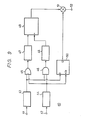
- Fig. 9 is a block diagram showing an example of an azimuth error detecting circuit
- Fig. 10 is a waveform diagram useful for the explanation thereof
- Fig. 10 is a waveform diagram useful for the explanation thereof
- FIG. 11 is a plan view showing an example of a prior art optical type record card
- Fig. 12 is a pattern diagram showing its sub-track
- Figs. 13 and 14 are a locational diagram showing an example of a prior art optical type record card reader and a perspective view showing a part thereof
- Fig. 15 is a pattern diagram showing a corresponding relationship between a line sensor and an image of a pit.
- Reference numeral 11 designates a cylindrical lens which is located between the focusing lens 8 and the line sensor 10.
- An xyz orthogonal coordinate system is provided, and along the z axis, there are sequentially located the optical type record card 1, the focusing lens 8, the cylindrical lens 11 and the line sensor 10 with predetermined distances. And, the respective elements are located in such a manner that the recording surface of the optical type record card 1, the cross section of the focusing lens 8- perpendicular to its optical axis, the plane of the cylindrical lens 11 and the light receiving surface of the line sensor 10 each exist on the xy plane. In this case, when the projected image of the sub-track T s to the line sensor 10 is inclined relative to the line sensor 10, the cylindrical lens 11 is rotated on the xy plane to thereby correct the azimuth error thereof.
- the light from the focusing lens 8 is traveled so as to be focused at the position on the z axis with a distance a from the plane lla of the cylindrical lens 11.
- the cylindrical lens 11 when the cylindrical lens 11 is provided, it is assumed that the light from the focusing lens 8 is refracted by this cylindrical lens 11 and is focused at the position apart by a distance b (this becomes the distance between the cylindrical lens 11 and the line sensor 10) on the z aixs from the plane lla of the cylindrical lens 11 and distant from the z axis by ⁇ .
- the 6 is proportionate to the Y. If the rotation angle of the image of the sub-track T S relative to the y axis when the cylindrical lens 11 is rotated relative to the y axis by the e is taken as a radian, the a is expressed by the following equation.
- Figs. 3 and 4 are respectively a longitudinal cross-sectional view of driving means 12 for the cylindrical lens 11 and a lateral cross-sectional view thereof.
- the cylindrical lens 11 is attached to a window frame 15 provided at one side of a lever 14 which is rotated together with a rotary shaft 13 extended in the z axis direction therearound.
- Reference numeral 16 designates a rotary bearing into which the rotary shaft 13 is inserted and reference numeral 17 designates a bearing therebetween.
- the rotary bearing 16 is attached to a fixed portion.
- This voice coil apparatus 18 is formed of a columnar center yoke 19 attached to the fixed portion, an outer yoke 21 of a cylindrical shape coupled to a circumference of a bottom disk portion 19a of the center york through a cylindrical shape magnet 20, a cylindrical bobbin 23 located between the center yoke 19 and the magnet 20 and the outer yoke 21 and around which a winding 22 is wound, a rod-shaped portion 24 protrusively provided at a ceiling portion 23a of the bobbin 23 and a coil spring 25 extended between the bobbin 23 and the outer yoke 21. Then, the bobbin 23 is attached through the rod-shaped portion 24 to the other side of the lever 14.
- the cylindrical lens 11 is not rotated around the z axis, if the rotary shaft 13 is very close to the z axis, the angle e is the very small one within a lens range of about ⁇ 1°, so that it can be judged that the cylindrical lens is rotated around the z axis.
- the distance between the center 11C of the plane of the cylindrical lens 11 and the center of the rotary shaft 13 is taken as l and the rotation angle of the cylindrical lens 11 is taken as ⁇
- the moving distance s of the center of the cylindrical lens 11 caused by the rotation thereof is expressed by the following equation.
- Figs. 6 and 7 are a longitudinal cross-sectional view of the driving means 12 for the cylindrical lens 11 and a front view showing a part thereof.
- Fig. 8 is a cross-sectional view taken along a line A-A in Fig. 7.
- This driving means 12 comprises a disk plate 30 which is attached through a pair of rubber springs 31 and 32 to the fixed portion and has a central window opening 30a attached with the cylindrical lens 11, four rollers 33 which rotatably guide this disk plate 30 around the center thereof, a pair of windings 34 and 35 attached on one surface of the disk plate 30 at its peripheral edge so as to become symmetrical relative to one diameter thereof and a U-shape yoke 36 in cross-section (attached to the fixed portion) including in its inside a magnet 37 opposing to the windings 34 and 35 and located so as to hold therein the windings 34 and 35.
- an azimuth error detecting circuit 40 which detects, when the projected image of the sub-track T S of the optical type record card 1 onto the line sensor 10 has an azimuth error relative to the line sensor 10, this azimuth error and flows a drive current corresponding to the amount of the azimuth error to the winding of the above mentioned driving means 12.
- Both the pulses (see Figs. 10C and 10D) are supplied to an OR circuit 45 and an AND circuit 46.
- the respective output pulses from the OR circuit 45 and the AND circuit 46 are shown in Figs. 10E and 10G, respectively and the time difference between the respective rising edges thereof is equivalent to the azimuth error.
- the output pulse from the OR circuit 45 is supplied to a triangular wave generating circuit 47 in which it is converted to a triangular wave.
- the resulting triangular wave (see Fig. 10F) is supplied to a sample and hold circuit 49 which is also supplied with a sampling pulse generated by supplying the output pulse of the AND circuit 46 to a sampling pulse generating circuit 48 and corresponding to the rising edge thereof whereby the triangular wave is sampled and then held.
- Fig. 10H shows the output of the sample and hold circuit 49.
- the header pulse and the trailer pulse from the pulse shaping circuits 43 and 44 are supplied to a D input terminal and a clock input terminal of a D-type flip-flop circuit 50 which generates a positive or negative identifying signal in response to whether the trailer pulse is advanced relative or delayed to the header pulse in phase.
- This identifying signal and the output of the sample and hold circuit 49 are supplied to a multiplier 51 and thereby multiplied with each other. Accordingly, from an output terminal 52, there is derived an azimuth error signal (see Fig. 101) which has a positive or negative code corresponding to the advanced or delayed phase of the trailer pulse relative to the header pulse.
- azimuth error signal is amplified at a proper gain and is supplied to the winding 22 or the windings 34 and 35 of the above mentioned driving means 12, it is possible to correct the azimuth error by rotating the cylindrical lens 11 in correspondence with the azimuth error.
- the driving means of the cylindrical lens can be constructed small in size and light in weight and thereby the cylindrical lens is driven, the power consumption is small, the response is rapid and the servo is stabilized.
- the cylindrical lens since the cylindrical lens is employed, the power density of the incident light on the line sensor becomes large and the S/N ratio of the reproduced signal becomes large.
Landscapes
- Engineering & Computer Science (AREA)
- Physics & Mathematics (AREA)
- Artificial Intelligence (AREA)
- Computer Vision & Pattern Recognition (AREA)
- General Physics & Mathematics (AREA)
- Theoretical Computer Science (AREA)
- Electromagnetism (AREA)
- Health & Medical Sciences (AREA)
- General Health & Medical Sciences (AREA)
- Toxicology (AREA)
- Optical Recording Or Reproduction (AREA)
- Optical Head (AREA)
Abstract
Description
- The present invention relates to a reader for an optically readable record card called an "optical type record card" in the following.
- Optical type record cards are also known as memory cards, software cards or the like. A prior art card of this kind will be described first with reference to Fig. 11. Reference numeral 1 generally designates an optical type record card. In this card 1, a main track TM of a band-shape is formed rectilinearly on a rectangular card substrate (record medium) lA along its longitudinal direction. The main track TM is formed of the alignment of a plurality of sub-tracks TS which are parallel to each other. Further, each sub-track TS is formed of the alignment of pits P as a plurality of optical dot-shaped recorded marks as shown in Fig. 12. Each sub-track TS is located perpendicularly to its alignment direction, that is, the longitudinal direction of the main track TM. On each sub-track TS, there is recorded a unit signal amount of a digitized signal of an information signal such as, video, audio, data signals and the like on the basis of the presence or absence of the pit P and the difference of the spacing between the pits.
- Although the pit P is a concavity on a light reflection layer formed on the card substrate lA, as an optical dot-shaped recorded mark, it may be possible to obtain a recorded mark formed on the basis of the difference between light reflectivities provided by the phase transfer between the crystal and amorphous on a layer of, for example, TeOx(x ≒ 1)
- Reference numerals la and lb designate both side edges of the
card substrate 1A and which are formed as the straight lines parallel to the main track TM. One side edge la is taken as a reference side edge. The respective side surfaces at both the side edges la and lb of the card substrate lA construct the planes perpendicular to the front and back surfaces of the card substrate lA which are made parallel to each other. - Subsequently, an optical type record card reader for reading from the card 1 the information signal recorded. on the main track Tm will be described with reference to Figs. 13 and 14. The card 1, which is entered through the insertion slot to the inside of the reader, is transported along the reference side edge la of the card 1 to the direction shown by an arrow 3 by
card transport rollers 2. An irradiation light 5 from a light source 4 irradiates the track Tm of the card 1 through a condenser lens 6 and a reflected light from the track TM, that is, aread light 7 of the track TM is irradiated through a focusinglens 8 to aline sensor 10 supported by a supportingplate 9, whereby the information signal is read out. Theline sensor 10 is formed of a CCD (charge coupled device). This is formed such that a plurality ofdetection elements 10a are arranged rectilinearly and from which an image projected thereon is read out by the electronic scanning. On theline sensor 10, the longitudinal direction of the image of the sub-track TS coincides with the alignment direction of thedetection elements 10a and images P' of all the pits P of one sub-track Ts are focused simultaneously on thephoto detector 10 so that the information signal of one sub-track T amount is read out at the same time. - Fig. 15 shows a corresponding relationship between the
line sensor 10 and the images P' of the pits P projected thereon. - By the way, while the optical type record card 1 is being transported, if the projected image of the sub-track Ts to the
line sensor 10 has an azimuth error relative to theline sensor 10, it becomes impossible to read the information of the sub-track TS. - Therefore, in the prior art, the azimuth error is corrected, that is, the azimuth error is reduced to zero by rotating the
line sensor 10. In this case, in practice, the substrate on which theline sensor 10, its driver, amplifier and the like are mounted must be rotated. In addition, because of the presence of the cords for the power source and the signal, it is very difficult to correct the azimuth error by rotating theline sensor 10 smoothly, highly precisely and rapidly. - In view of such aspect, the present invention is to provide the optical type record card reader which can correct the azimuth error of the projected image of the sub-track on the optical type record card to the line sensor smoothly, highly precisely and rapidly.
- The present invention is characterized by a light source for irradiating a track of an optical type record card in which an information is recorded on a record medium in the form of a plurality of tracks parallel to one another and which can be optically read, a line sensor for reading the information by a reflected light from the track, a cylindrical lens located between the optical type record card and the line sensor and supported so as to be freely rotatable, an azimuth error detecting circuit for detecting an azimuth error occurring between the track and the line sensor and driving means for driving the cylindrical lens by the detected output of the azimuth error detecting circuit.
- Fig. 1 is a locational diagram showing one embodiment of the present invention, Fig. 2 is a diagram used to explain its optical system, Figs. 3 and 4 are a longitudinal cross-sectional view and a lateral cross-sectional view respectively showing an example of driving means for a cylindrical lens, Fig. 5 is a diagram used to explain the same, Figs. 6 and 7 are a longitudinal cross-sectional view of other example of the driving means for the cylindrical lens and a front view showing a part thereof, Fig. 8 is a cross-sectional view taken along a line A-A in Fig. 7, Fig. 9 is a block diagram showing an example of an azimuth error detecting circuit, Fig. 10 is a waveform diagram useful for the explanation thereof, Fig. 11 is a plan view showing an example of a prior art optical type record card, Fig. 12 is a pattern diagram showing its sub-track, Figs. 13 and 14 are a locational diagram showing an example of a prior art optical type record card reader and a perspective view showing a part thereof and Fig. 15 is a pattern diagram showing a corresponding relationship between a line sensor and an image of a pit.
- A fundamental embodiment of the present invention will hereinafter be described with reference to Fig. 1. In the figure, like parts corresponding to those of Figs. 11 to 15 are marked with the same references and the overlapping explanation thereof will be omitted.
Reference numeral 11 designates a cylindrical lens which is located between the focusinglens 8 and theline sensor 10. - An xyz orthogonal coordinate system is provided, and along the z axis, there are sequentially located the optical type record card 1, the focusing
lens 8, thecylindrical lens 11 and theline sensor 10 with predetermined distances. And, the respective elements are located in such a manner that the recording surface of the optical type record card 1, the cross section of the focusing lens 8- perpendicular to its optical axis, the plane of thecylindrical lens 11 and the light receiving surface of theline sensor 10 each exist on the xy plane. In this case, when the projected image of the sub-track Ts to theline sensor 10 is inclined relative to theline sensor 10, thecylindrical lens 11 is rotated on the xy plane to thereby correct the azimuth error thereof. - Accordingly, referring to Fig. 2, the following discussion will be given on a case in which how much angle the image of the sub-track TS on the
line sensor 10 will be inclined when the longitudinal direction of each of the sub-track TS and theline sensor 10 is made coincident with the y axis and when the longitudinal direction of thecylindrical lens 11 is inclined relative to the y axis by 6 radian within the xy plane. - Fig. 2 shows a light path of a light which passes through the
lens 11 when thecylindrical lens 11 is cut out by the xz plane in which y = Y is satisfied. Reference letter d in Fig. 2 designates the displacement amount (length) of the position at y = Y from the z axis when a plane lla of thecylindrical lens 11 is inclined by 8 within the xy plane. When there is provided nocylindrical lens 11, the light from the focusinglens 8 is traveled so as to be focused at the position on the z axis with a distance a from the plane lla of thecylindrical lens 11. On the contrary, when thecylindrical lens 11 is provided, it is assumed that the light from the focusinglens 8 is refracted by thiscylindrical lens 11 and is focused at the position apart by a distance b (this becomes the distance between thecylindrical lens 11 and the line sensor 10) on the z aixs from the plane lla of thecylindrical lens 11 and distant from the z axis by δ. - Accordingly, if the focal length of the
cylindrical lens 11 is taken as f, the following equation is established among a, b, and f from the formula of the lens.
- Further, the 6 is expressed by the following equation.

- Accordingly, it will be clear that the 6 is proportionate to the Y. If the rotation angle of the image of the sub-track TS relative to the y axis when the
cylindrical lens 11 is rotated relative to the y axis by the e is taken as a radian, the a is expressed by the following equation.
- Here, if the a and e are sufficiently small, the Eq. (3) is approximated as the following equation.

- For example, let it be assumed that f = 40 (mm), a = 20 (mm) and b = 13.3 (mm). Then, (a - b)/a becomes 0.33. Accordingly, if the
cylindrical lens 11 is rotated by 1° within the xy plane, the image of the sub-track TS is rotated by 0.33°. - Subsequently, one example of the driving means for the
cylindrical lens 11 will be described with reference to Figs. 3 and 4. Figs. 3 and 4 are respectively a longitudinal cross-sectional view of driving means 12 for thecylindrical lens 11 and a lateral cross-sectional view thereof. Thecylindrical lens 11 is attached to awindow frame 15 provided at one side of alever 14 which is rotated together with arotary shaft 13 extended in the z axis direction therearound.Reference numeral 16 designates a rotary bearing into which therotary shaft 13 is inserted andreference numeral 17 designates a bearing therebetween. Therotary bearing 16 is attached to a fixed portion. - To the other side of the
lever 14, there is attached avoice coil apparatus 18. Thisvoice coil apparatus 18 is formed of acolumnar center yoke 19 attached to the fixed portion, anouter yoke 21 of a cylindrical shape coupled to a circumference of abottom disk portion 19a of the center york through acylindrical shape magnet 20, acylindrical bobbin 23 located between thecenter yoke 19 and themagnet 20 and theouter yoke 21 and around which a winding 22 is wound, a rod-shaped portion 24 protrusively provided at aceiling portion 23a of thebobbin 23 and acoil spring 25 extended between thebobbin 23 and theouter yoke 21. Then, thebobbin 23 is attached through the rod-shaped portion 24 to the other side of thelever 14. - Accordingly, if a drive current is flowed to the winding 22, the
bobbin 23 is moved in its axial direction, whereby thelever 14 is rotated and accordingly, thecylindrical lens 11 is rotated. - If it is assumed that the length from the
rotary shaft 13 to the root of the rod-shaped portion 24 as L and the moving distance of thebobbin 23 as ΔZ, the rotation angle θ (radian) of thecylindrical lens 11 satisfies the equation, θ ≒ ΔZ/L where this angle is very small. If L = 30 (mm) and ΔZ = 1 (mm), 6 = 1.9° is established. - While in this embodiment the
cylindrical lens 11 is not rotated around the z axis, if therotary shaft 13 is very close to the z axis, the angle e is the very small one within a lens range of about ± 1°, so that it can be judged that the cylindrical lens is rotated around the z axis. In other words, as shown in Fig. 5, if the distance between thecenter 11C of the plane of thecylindrical lens 11 and the center of therotary shaft 13 is taken as ℓ and the rotation angle of thecylindrical lens 11 is taken as θ, the moving distance s of the center of thecylindrical lens 11 caused by the rotation thereof is expressed by the following equation.
- If ℓ = 11 (mm) and θ = 1°, the moving distance s becomes about 0.2 mm.
- Other example of the driving means for the
cylindrical lens 11 will be described with reference to Figs. 6, 7 and 8. Figs. 6 and 7 are a longitudinal cross-sectional view of the driving means 12 for thecylindrical lens 11 and a front view showing a part thereof. Fig. 8 is a cross-sectional view taken along a line A-A in Fig. 7. This driving means 12 comprises adisk plate 30 which is attached through a pair of rubber springs 31 and 32 to the fixed portion and has acentral window opening 30a attached with thecylindrical lens 11, fourrollers 33 which rotatably guide thisdisk plate 30 around the center thereof, a pair ofwindings disk plate 30 at its peripheral edge so as to become symmetrical relative to one diameter thereof and aU-shape yoke 36 in cross-section (attached to the fixed portion) including in its inside amagnet 37 opposing to thewindings windings - Accordingly, if a drive current is flowed to the
windings disk plate 30 is rotated to thereby rotate thecylindrical lens 11. - Referring to Fig. 9, an explanation will be given on one example of an azimuth
error detecting circuit 40 which detects, when the projected image of the sub-track TS of the optical type record card 1 onto theline sensor 10 has an azimuth error relative to theline sensor 10, this azimuth error and flows a drive current corresponding to the amount of the azimuth error to the winding of the above mentioned driving means 12. - A header pulse (see Fig. 10A) and a trailer pulse (see Fig. 10B), which are based on one end and the other end of the projected image of the sub-track TS of the optical type record card 1 onto the line sensor 10 (different photo detector may be possible), are generated from the
line sensor 10 and then respectively supplied throughinput terminals pulse shaping circuits OR circuit 45 and an ANDcircuit 46. The respective output pulses from theOR circuit 45 and the ANDcircuit 46 are shown in Figs. 10E and 10G, respectively and the time difference between the respective rising edges thereof is equivalent to the azimuth error. Therefore, the output pulse from theOR circuit 45 is supplied to a triangularwave generating circuit 47 in which it is converted to a triangular wave. The resulting triangular wave (see Fig. 10F) is supplied to a sample and holdcircuit 49 which is also supplied with a sampling pulse generated by supplying the output pulse of the ANDcircuit 46 to a samplingpulse generating circuit 48 and corresponding to the rising edge thereof whereby the triangular wave is sampled and then held. Fig. 10H shows the output of the sample and holdcircuit 49. - On the other hand, the header pulse and the trailer pulse from the
pulse shaping circuits flop circuit 50 which generates a positive or negative identifying signal in response to whether the trailer pulse is advanced relative or delayed to the header pulse in phase. This identifying signal and the output of the sample and holdcircuit 49 are supplied to amultiplier 51 and thereby multiplied with each other. Accordingly, from anoutput terminal 52, there is derived an azimuth error signal (see Fig. 101) which has a positive or negative code corresponding to the advanced or delayed phase of the trailer pulse relative to the header pulse. - Accordingly, if such azimuth error signal is amplified at a proper gain and is supplied to the winding 22 or the
windings cylindrical lens 11 in correspondence with the azimuth error. - According to the present invention as described above, it is possible to obtain an optical type record card reader in which the azimuth error of the projected image of the sub-track of the optical type record card onto the line sensor can be corrected smoothly, highly precisely and rapidly by the rotation of the cylindrical lens.
- Further, since the driving means of the cylindrical lens can be constructed small in size and light in weight and thereby the cylindrical lens is driven, the power consumption is small, the response is rapid and the servo is stabilized.
- Furthermore, since the cylindrical lens is employed, the power density of the incident light on the line sensor becomes large and the S/N ratio of the reproduced signal becomes large.
Claims (5)
Applications Claiming Priority (2)
| Application Number | Priority Date | Filing Date | Title |
|---|---|---|---|
| JP260398/84 | 1984-12-10 | ||
| JP59260398A JPS61138379A (en) | 1984-12-10 | 1984-12-10 | Reader of optical recording card |
Publications (3)
| Publication Number | Publication Date |
|---|---|
| EP0207163A1 true EP0207163A1 (en) | 1987-01-07 |
| EP0207163A4 EP0207163A4 (en) | 1988-12-15 |
| EP0207163B1 EP0207163B1 (en) | 1993-02-24 |
Family
ID=17347363
Family Applications (1)
| Application Number | Title | Priority Date | Filing Date |
|---|---|---|---|
| EP86900238A Expired - Lifetime EP0207163B1 (en) | 1984-12-10 | 1985-12-05 | Apparatus for reading optical recording cards |
Country Status (6)
| Country | Link |
|---|---|
| US (1) | US4777356A (en) |
| EP (1) | EP0207163B1 (en) |
| JP (1) | JPS61138379A (en) |
| KR (1) | KR930009739B1 (en) |
| DE (1) | DE3587121T2 (en) |
| WO (1) | WO1986003611A1 (en) |
Cited By (1)
| Publication number | Priority date | Publication date | Assignee | Title |
|---|---|---|---|---|
| EP0583514A1 (en) * | 1992-08-19 | 1994-02-23 | Opticon Sensors Europe B.V. | Focusing means for a symbol code reader |
Families Citing this family (6)
| Publication number | Priority date | Publication date | Assignee | Title |
|---|---|---|---|---|
| WO1987003131A1 (en) * | 1985-11-18 | 1987-05-21 | Sony Corporation | Optical card reader |
| US5280160A (en) * | 1987-02-27 | 1994-01-18 | Canon Kabushiki Kaisha | Recording and reproducing method and apparatus compensating for predicted deviation based on detected relative skewing of recording medium |
| JP2624688B2 (en) * | 1987-06-25 | 1997-06-25 | 大日本印刷株式会社 | Optical data recording medium reader |
| US5179268A (en) * | 1987-07-22 | 1993-01-12 | Omron Tateisi Electronic Co. | Apparatus for detecting inclination of an optical card |
| CA1334218C (en) * | 1989-03-01 | 1995-01-31 | Jerome Swartz | Hand-held laser scanning for reading two dimensional bar codes |
| JP2007074806A (en) * | 2005-09-06 | 2007-03-22 | Morio Koide | Piston engine |
Citations (4)
| Publication number | Priority date | Publication date | Assignee | Title |
|---|---|---|---|---|
| US2938962A (en) * | 1955-07-12 | 1960-05-31 | Konins | Azimuth seeking reproducing head |
| JPS56114124A (en) * | 1980-02-14 | 1981-09-08 | Fujitsu Ltd | Multitrack head position detection |
| EP0061194A2 (en) * | 1981-03-24 | 1982-09-29 | Kabushiki Kaisha Toshiba | Optical recording device |
| WO1985001818A1 (en) * | 1983-10-12 | 1985-04-25 | Drexler Technology Corporation | Quad density optical data system |
Family Cites Families (1)
| Publication number | Priority date | Publication date | Assignee | Title |
|---|---|---|---|---|
| JPS51137426A (en) * | 1975-05-24 | 1976-11-27 | Nippon Telegr & Teleph Corp <Ntt> | Image rotating device |
-
1984
- 1984-12-10 JP JP59260398A patent/JPS61138379A/en active Granted
-
1985
- 1985-12-05 DE DE8686900238T patent/DE3587121T2/en not_active Expired - Fee Related
- 1985-12-05 KR KR1019860700545A patent/KR930009739B1/en not_active IP Right Cessation
- 1985-12-05 WO PCT/JP1985/000669 patent/WO1986003611A1/en active IP Right Grant
- 1985-12-05 EP EP86900238A patent/EP0207163B1/en not_active Expired - Lifetime
- 1985-12-05 US US06/905,586 patent/US4777356A/en not_active Expired - Fee Related
Patent Citations (4)
| Publication number | Priority date | Publication date | Assignee | Title |
|---|---|---|---|---|
| US2938962A (en) * | 1955-07-12 | 1960-05-31 | Konins | Azimuth seeking reproducing head |
| JPS56114124A (en) * | 1980-02-14 | 1981-09-08 | Fujitsu Ltd | Multitrack head position detection |
| EP0061194A2 (en) * | 1981-03-24 | 1982-09-29 | Kabushiki Kaisha Toshiba | Optical recording device |
| WO1985001818A1 (en) * | 1983-10-12 | 1985-04-25 | Drexler Technology Corporation | Quad density optical data system |
Non-Patent Citations (2)
| Title |
|---|
| PATENT ABSTRACTS OF JAPAN, vol. 5, no. 185 (P-91)[857], 25th November 1981; & JP-A-56 114 124 (FUJITSU K.K.) 08-09-1981 * |
| See also references of WO8603611A1 * |
Cited By (2)
| Publication number | Priority date | Publication date | Assignee | Title |
|---|---|---|---|---|
| EP0583514A1 (en) * | 1992-08-19 | 1994-02-23 | Opticon Sensors Europe B.V. | Focusing means for a symbol code reader |
| US5365049A (en) * | 1992-08-19 | 1994-11-15 | Opticon Sensors Europe B.V. | Focusing means for a symbol code reader |
Also Published As
| Publication number | Publication date |
|---|---|
| KR930009739B1 (en) | 1993-10-09 |
| EP0207163A4 (en) | 1988-12-15 |
| KR870700161A (en) | 1987-03-14 |
| EP0207163B1 (en) | 1993-02-24 |
| DE3587121T2 (en) | 1993-07-01 |
| US4777356A (en) | 1988-10-11 |
| JPS61138379A (en) | 1986-06-25 |
| DE3587121D1 (en) | 1993-04-01 |
| JPH0576661B2 (en) | 1993-10-25 |
| WO1986003611A1 (en) | 1986-06-19 |
Similar Documents
| Publication | Publication Date | Title |
|---|---|---|
| US5131744A (en) | Mirror rotation angle detection mechanism | |
| US3898629A (en) | Apparatus for scanning a data record medium | |
| JPH02503369A (en) | Read-only optical cards and systems | |
| JPH02501335A (en) | Transparent readout quad density optical data system | |
| GB1534381A (en) | Apparatus for reading a record carrier with an optically readable information structure | |
| US4273998A (en) | Servo unit for optical type information reading device | |
| EP0207163B1 (en) | Apparatus for reading optical recording cards | |
| CA1292571C (en) | Optical recording medium and method and apparatus for correcting angular deviation thereof | |
| KR870005376A (en) | Optical reading and writing devices | |
| KR0150264B1 (en) | Optical recording medium and recording reproducing system | |
| US5179267A (en) | Data reading and/or writing apparatus of type using optical card | |
| JPS62126376A (en) | Reflection type optical coupling element | |
| JP2005078735A (en) | Optical disk device | |
| JPS6257168A (en) | Discriminating device for recording medium | |
| JPS6383929A (en) | Disk fluctuation state detection device | |
| JP2856356B2 (en) | Optical information reader | |
| JPS6366736A (en) | Detecting device for tilted degree of disk | |
| JP2974560B2 (en) | Information recording / reproducing device | |
| JPS5828652B2 (en) | Yomitori Sochi | |
| JPS5810195Y2 (en) | Optical reproduction device for information signals | |
| EP0577369A2 (en) | Optical head and optical information reading apparatus | |
| JPS6044727B2 (en) | Media position detection method in focus servo | |
| JPS63119026A (en) | Optical system driving device | |
| JPS62141640A (en) | Objective lens position detector | |
| JPH01205390A (en) | Information reproducing device |
Legal Events
| Date | Code | Title | Description |
|---|---|---|---|
| PUAI | Public reference made under article 153(3) epc to a published international application that has entered the european phase |
Free format text: ORIGINAL CODE: 0009012 |
|
| AK | Designated contracting states |
Kind code of ref document: A1 Designated state(s): CH DE FR GB IT LI |
|
| 17P | Request for examination filed |
Effective date: 19861211 |
|
| A4 | Supplementary search report drawn up and despatched |
Effective date: 19881215 |
|
| 17Q | First examination report despatched |
Effective date: 19900719 |
|
| GRAA | (expected) grant |
Free format text: ORIGINAL CODE: 0009210 |
|
| AK | Designated contracting states |
Kind code of ref document: B1 Designated state(s): CH DE FR GB IT LI |
|
| REF | Corresponds to: |
Ref document number: 3587121 Country of ref document: DE Date of ref document: 19930401 |
|
| ITF | It: translation for a ep patent filed | ||
| ET | Fr: translation filed | ||
| PLBE | No opposition filed within time limit |
Free format text: ORIGINAL CODE: 0009261 |
|
| STAA | Information on the status of an ep patent application or granted ep patent |
Free format text: STATUS: NO OPPOSITION FILED WITHIN TIME LIMIT |
|
| 26N | No opposition filed | ||
| ITTA | It: last paid annual fee | ||
| PGFP | Annual fee paid to national office [announced via postgrant information from national office to epo] |
Ref country code: GB Payment date: 19951127 Year of fee payment: 11 |
|
| PGFP | Annual fee paid to national office [announced via postgrant information from national office to epo] |
Ref country code: FR Payment date: 19951212 Year of fee payment: 11 |
|
| PGFP | Annual fee paid to national office [announced via postgrant information from national office to epo] |
Ref country code: DE Payment date: 19951214 Year of fee payment: 11 |
|
| PGFP | Annual fee paid to national office [announced via postgrant information from national office to epo] |
Ref country code: CH Payment date: 19951229 Year of fee payment: 11 |
|
| PG25 | Lapsed in a contracting state [announced via postgrant information from national office to epo] |
Ref country code: GB Effective date: 19961205 |
|
| PG25 | Lapsed in a contracting state [announced via postgrant information from national office to epo] |
Ref country code: LI Effective date: 19961231 Ref country code: CH Effective date: 19961231 |
|
| GBPC | Gb: european patent ceased through non-payment of renewal fee |
Effective date: 19961205 |
|
| REG | Reference to a national code |
Ref country code: CH Ref legal event code: PL |
|
| PG25 | Lapsed in a contracting state [announced via postgrant information from national office to epo] |
Ref country code: FR Effective date: 19970829 |
|
| PG25 | Lapsed in a contracting state [announced via postgrant information from national office to epo] |
Ref country code: DE Effective date: 19970902 |
|
| REG | Reference to a national code |
Ref country code: FR Ref legal event code: ST |