EP0207033B1 - Magazine for automatic artillery pieces - Google Patents
Magazine for automatic artillery pieces Download PDFInfo
- Publication number
- EP0207033B1 EP0207033B1 EP19860850219 EP86850219A EP0207033B1 EP 0207033 B1 EP0207033 B1 EP 0207033B1 EP 19860850219 EP19860850219 EP 19860850219 EP 86850219 A EP86850219 A EP 86850219A EP 0207033 B1 EP0207033 B1 EP 0207033B1
- Authority
- EP
- European Patent Office
- Prior art keywords
- round
- compartment
- rounds
- compartments
- gun
- Prior art date
- Legal status (The legal status is an assumption and is not a legal conclusion. Google has not performed a legal analysis and makes no representation as to the accuracy of the status listed.)
- Expired
Links
- 230000007246 mechanism Effects 0.000 claims description 14
- 230000006870 function Effects 0.000 description 14
- 230000004913 activation Effects 0.000 description 2
- 238000010276 construction Methods 0.000 description 2
- 230000001960 triggered effect Effects 0.000 description 2
- 230000009471 action Effects 0.000 description 1
- 230000003213 activating effect Effects 0.000 description 1
- 230000008901 benefit Effects 0.000 description 1
- 230000008878 coupling Effects 0.000 description 1
- 238000010168 coupling process Methods 0.000 description 1
- 238000005859 coupling reaction Methods 0.000 description 1
- 230000000994 depressogenic effect Effects 0.000 description 1
- 238000012840 feeding operation Methods 0.000 description 1
- 238000010304 firing Methods 0.000 description 1
- 230000008571 general function Effects 0.000 description 1
- 230000002452 interceptive effect Effects 0.000 description 1
- 238000000034 method Methods 0.000 description 1
- 230000008569 process Effects 0.000 description 1
- 230000000717 retained effect Effects 0.000 description 1
Images



Classifications
-
- F—MECHANICAL ENGINEERING; LIGHTING; HEATING; WEAPONS; BLASTING
- F41—WEAPONS
- F41A—FUNCTIONAL FEATURES OR DETAILS COMMON TO BOTH SMALLARMS AND ORDNANCE, e.g. CANNONS; MOUNTINGS FOR SMALLARMS OR ORDNANCE
- F41A9/00—Feeding or loading of ammunition; Magazines; Guiding means for the extracting of cartridges
- F41A9/61—Magazines
- F41A9/64—Magazines for unbelted ammunition
- F41A9/65—Box magazines having a cartridge follower
- F41A9/68—Plural magazines, e.g. tandem magazines ; Arrangements of cartridges in two or more independent rows or channels which are selectively or sequentially brought into operative position
Definitions
- the present invention relates to a compact, preferably gun-mounted, magazine for fully automatic artillery pieces, primarily anti-aircraft guns.
- the magazine according to the present invention comprises a plurality of preferably vertical compartments for rounds of ammunition, the compartments being disposed in side-by-side parallel relationship and each accommodating a number of parallel superposed rounds, which may progressively be fed down to a discharge position specific to each compartment, whence the rounds are fed further towards the ramming position of the gun by means of a transverse feeding system common to all compartments by the intermediary of a transverse feeding channel which coincides with the mutually parallel discharge positions for all compartments, and the transverse feeding channel being, when the gun is fired, successively fed with new rounds at the same rate as rounds are fed into the gun, from that compartment which lies most distal from the ramming position of the gun and which has not yet been emptied.
- the invention as such particularly relates to certain releasable round hoists for said vertical magazine compartments. Said round hoists keeping the feeding channel free from rounds from every magazine compartment except the most distal one still containing rounds and which is delivering new rounds to the feeding channel until it is emptied when the next compartment is activated.
- a gun magazine of the same main type as the magazine according to the preamble of claim 1 is already known through GB-A 1 138 286.
- a distinct advantage inherent in both these magazines is that they may, since the discharge positions for the different round compartments coincide with the transverse feeding channel, be directly loaded right up to the ramming position of the gun without a successive and time-consuming stepwise feeding of the rounds for successive replenishment of a separate feeding channel.
- This latter situation is, otherwise, the normal arrangement in gun magazines for large quantities of rounds. These are, moreover, often placed in the gun mounting instead of directly on the piece.
- the gun-mounted magazines seldom accommodate more than from 10 to 20 rounds.
- the magazine according to the present invention can, because it may be made so compact, be built for 100 rounds and more even in calibres of from 40-57 mm.
- the previously-mentioned simultaneous loading of the compartments and transverse feeding channel is effected in that the compartments are filled and the transverse feeding channel is also automatically filled.
- all compartments are provided with round hoists which are activated once the compartments have been filled. The round hoists then lift all rounds apart from the first in each compartment so that there is created a free channel between the first rounds located in the transverse feeding channel and remaining rounds.
- said round hoists are provided with self-locking toggle mechanisms which are influenced by certain sensors disposed at each magazine compartment and which as soon as it is ascertained that no round is located in its section of the transverse feeding channel, activates the round hoist in the next compartment in the direction of feed so that the rounds located in this compartment are given free passage to the transverse feeding channel.
- the most distal compartment which, thus, is always to commence feeding rounds, has no round hoist. As a result of this arrangement, compartment after compartment will be successively emptied into the transverse feeding channel.
- the anti-aircraft gun 1 illustrated in Fig. 1 is provided with two gun-mounted magazines 2 and 3 respectively.
- a vertical gun feed channel 4 is disposed between the round magazines and may receive rounds from either one of the magazines 2 or 3 and feed these into the ramming position of the gun.
- the magazines may be filled with different types of ammunition and the choice of magazine may be directly related to the target in question by means of separate command devices.
- the magazines are provided with opening lids for replenishment with new rounds from above.
- the lid 5 on the magazine 2 is shown in the half-open position.
- the round magazine 2 illustrated in section in Fig. 2 comprises six compartments I-VI containing a total of 54 rounds numbered in the sequence they are fed towards the gun. Rounds numbers 1 and 2 are missing from the number series in the figure, since these rounds are loaded direct in the gun feeding channel 4.
- the different compartments I-IV each have their discharge position which together form the transverse feeding channel 6 of the magazine. Rounds 3-8 are located in this transverse feeding channel.
- a transverse feeding device 7 of the stepwise advancement type runs along the bottom of the transverse feeding channel 6. This will not be discussed in detail in the body of this disclosure and on the Drawings, since it does not, in actual fact, form part of the present invention. Its construction may also be designed in a number of different ways. Its general function is based on the circumstance that, for each round discharged by the gun, it advances the rounds located in the feeding channel 6 one step nearer and into the feed channel 4 of the gun.
- each respective compartment is filled with at least one round so that all discharge positions along the transverse feeding channel 6 are filled.
- these round hoists 8 When the compartments are filled, these round hoists 8 must be in the disengaged position, i.e. they must leave the compartments completely free so that these may be filled completely right down even to each respective discharge position.
- Each compartment is further provided with a vertical feeder which guarantees uninterrupted feeding of the rounds along each respective compartment irrespective of the elevation of the gun.
- the vertical feeders are not shown on the Drawings since they do not form part of the present invention and are, moreover, of conventional construction.
- the vertical feeders may, for example, consist of hydraulically or spring-loaded feeding arms which act upon the uppermost round in each compartment.
- rounds numbers 1 and 2 are placed in the gun feeding channel 4, whereafter the vertical feeders are activated.
- the lid 5 of the magazine is closed.
- the lid is either directly interconnected with a special operating function or this function is activated separately.
- the round hoists 8 - which, when the compartments were filled were in the disengaged position - are moved to the position illustrated in Figs. 2 and 4 where they lift all rounds in each compartment, apart from the rounds located in the discharge positions, a height sufficient to form a free channel between the rounds located along the transverse feeding channel 6 and the remaining rounds in the compartments.
- compartment I has no round hoist. Hence, the rounds in this compartment enjoy free access to the discharge position of the compartment.
- the rounds are, thus, fed by the transverse feeder 7 successively along the transverse feeding channel 6 in the direction of the arrow b at the same time as the transverse feeding channel is replenished with fresh rounds, starting with compartment I.
- All compartments apart from compartment VI are, furthermore, provided with sensors generally designated 9 (see Fig. 4 and Figs. 6a and 6b).
- the sensors for the emptied compartment trigger the round hoist in the subsequent compartment, seen in the feeding direction, which, thus, assumes the role of supplying new rounds to the transverse feeding channel.
- the sensors 9 are placed in the bottom of the transverse feeding channel 6 where they are acted upon by the rounds advanced along this channel.
- the more detailed function of the sensors 9 will be discussed in depth below, together with other mechanical arrangements according to the present invention. However, the invention should not be considered as restricted to those arrangements and solutions illustrated on the Drawings. These are rather to be considered as exemplifying preferred embodiments.
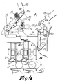
- the function of the round hoists 8 and the sensors 9 will primarily be apparent from Figs. 4-6.
- This operating function may, for example, consist of a number of linkage arms which are interconnected with one another and with the lid, for example as follows.
- the lid 5 shifts a first link 10 from the position 1 Oa to 1 Ob and the arm 11 is thereby depressed the same distance about its shaft 15.
- a lock 12 and a spring buffer 13 are disposed on the arm 11.
- the lock 12 entrains the arm 14.
- a fixed arrest 16 triggers the spring buffer 13 which, in its turn, triggers the lock 12 which releases its grip in the arm 14 which thereupon returns to its initial position under the action of a return buffer 17 disposed further ahead in the coupling chain.
- the arm 14 has a rear overhang 18 at which a link 19 is fixedly anchored.
- the link 19 is shifted in the direction of the arrow and, in its turn, shifts the links 20-24 in the direction of the arrows.
- the links 20, 21 and 22 are fixedly mounted on the same shaft and pivot as a unit.
- the link 24 is fixedly mounted on the same shaft as the link 25 in Figs. 5a and b.
- the link 25 is interconnected with the links 26 and 27.
- the angled arm 28 When the linkage system 24-27 is activated in the direction of the arrows, the angled arm 28 is shifted at the same time and, in its turn, acts upon the link 29 which in turn acts on a cranked link 30 which is journalled about a shaft 31 and is pivotally connected with the link 29 at its one arm 32 and with a second cranked link 34 at its other arm 33.
- the second cranked link 34 is, in its turn, connected, at its other end, to the pivot arm 33 which is fixedly retained on the same shaft as the previously-mentioned round hoist 8.
- the sensing arm 9 When the sensing arm 9 is no longer loaded by a round, in other words when the compartment has been emptied, the sensing arm shifts the link 37 in the direction of the arrow. On this movement, a compartment release block 38 is shifted from the first position beyond the toggle mechanism 31-33-34 to a second position where the compartment release block 38 bridges the distance between the tripping point of the toggle mechanism, i.e. the point which trips the lock if it is actuated in the right direction, and a tripping abutment 39 (only included on Figs. 6a and 6b) which is interactive with the gun recoil and, for each discharge recoil, passes the above-mentioned point but itself does not reach the critical point on the toggle mechanism.
- the round hoist 8 will be released on the first recoil once the compartment release block 38 has been shifted to its second position.
- the round hoist 8 may be provided with a release spring (35, not shown on the Drawings) which actuates the round hoist 8 in the release direction.
- the round hoists in all compartments function in the above-described manner and the system thus guarantees a reliable feed function until all compartments have been emptied.
Landscapes
- Engineering & Computer Science (AREA)
- General Engineering & Computer Science (AREA)
- Toys (AREA)
- Cigarettes, Filters, And Manufacturing Of Filters (AREA)
- Closures For Containers (AREA)
Description
- The present invention relates to a compact, preferably gun-mounted, magazine for fully automatic artillery pieces, primarily anti-aircraft guns.
- The magazine according to the present invention comprises a plurality of preferably vertical compartments for rounds of ammunition, the compartments being disposed in side-by-side parallel relationship and each accommodating a number of parallel superposed rounds, which may progressively be fed down to a discharge position specific to each compartment, whence the rounds are fed further towards the ramming position of the gun by means of a transverse feeding system common to all compartments by the intermediary of a transverse feeding channel which coincides with the mutually parallel discharge positions for all compartments, and the transverse feeding channel being, when the gun is fired, successively fed with new rounds at the same rate as rounds are fed into the gun, from that compartment which lies most distal from the ramming position of the gun and which has not yet been emptied.
- The invention as such particularly relates to certain releasable round hoists for said vertical magazine compartments. Said round hoists keeping the feeding channel free from rounds from every magazine compartment except the most distal one still containing rounds and which is delivering new rounds to the feeding channel until it is emptied when the next compartment is activated.
- A gun magazine of the same main type as the magazine according to the preamble of
claim 1 is already known through GB-A 1 138 286. - A distinct advantage inherent in both these magazines is that they may, since the discharge positions for the different round compartments coincide with the transverse feeding channel, be directly loaded right up to the ramming position of the gun without a successive and time-consuming stepwise feeding of the rounds for successive replenishment of a separate feeding channel. This latter situation is, otherwise, the normal arrangement in gun magazines for large quantities of rounds. These are, moreover, often placed in the gun mounting instead of directly on the piece. As soon as calibres in excess of the very smallest gun calibres of about 20 mm come into question, the gun-mounted magazines seldom accommodate more than from 10 to 20 rounds. The magazine according to the present invention can, because it may be made so compact, be built for 100 rounds and more even in calibres of from 40-57 mm.
- The previously-mentioned simultaneous loading of the compartments and transverse feeding channel is effected in that the compartments are filled and the transverse feeding channel is also automatically filled. In order that the rounds in those compartments which are not yet in turn to supply further rounds to the transverse feeding channel during firing shall not disturb the round feeding operation along the transverse feeding channel, all compartments are provided with round hoists which are activated once the compartments have been filled. The round hoists then lift all rounds apart from the first in each compartment so that there is created a free channel between the first rounds located in the transverse feeding channel and remaining rounds.
- The design according to GB-A 1 138 286, however, does not discuss the actual design and function of said round hoists but gives a very careful description of a somewhat delicate transverse feeding system. The present invention on the contrary particularly concerns with the design and function of said round hoists.
- According to the characterizing portion of
claim 1, said round hoists are provided with self-locking toggle mechanisms which are influenced by certain sensors disposed at each magazine compartment and which as soon as it is ascertained that no round is located in its section of the transverse feeding channel, activates the round hoist in the next compartment in the direction of feed so that the rounds located in this compartment are given free passage to the transverse feeding channel. The most distal compartment which, thus, is always to commence feeding rounds, has no round hoist. As a result of this arrangement, compartment after compartment will be successively emptied into the transverse feeding channel. For securing the round hoists in the raised position, use is made of self-locking toggle mechanisms of per se known type, and for the successive disengagement of these, use is made, according to the present invention, of compartment release blocks which are shiftable by the intermediary of the above-mentioned sensors and, when they have been shifted to the disengagement position, bridge the distance between the toggle mechanism and special triggering abutments which, on recoil of the gun, are shifted in a direction towards each respective toggle but which, without the triggering abutments as make-up pieces, do not reach all the way. This arrangement entails that the sensors only shift the compartment release blocks which possess slight natural mass, while release of the toggle mechanisms is catered for by the recoil of the gun. - Hence, activation of all round hoists is to be effected once the compartments have been filled. It may, therefore, be appropriate to provide the compartments with a common lid which is interconnected with a device which activates the round hoists when the lid is closed.
- The nature of the present invention and its aspects will be more readily understood from the following brief description of the accompanying Drawings, and discussion relating thereto.
- In the accompanying Drawings:
- Fig. 1 is an oblique projection of an anti-aircraft gun with two gun-mounted round magazines, one on each side;
- Fig. 2 shows, on a larger scale, a cross-section through one of these magazines;
- Fig. 3 is a section taken along the line III-III in Fig. 2;
- Fig. 4 shows, on a yet larger scale and with more details, parts of the sections A-A and B-B of Fig. 3;
- Figs. 5a and 5b show, on the same scale and wealth of detail as Fig. 4, parts of the section C-C of Fig. 3, Fig. 5a illustrating the incorporated linkage system in the released position and Fig. 5b showing the same linkage system in the captive position; and
- Figs. 6a and 6b illustrate the principle for the triggering and release function of the linkage system of Figs. 5a and b, Figure 6a illustrating the captive position and Fig. 6b the released position.
- Corresponding details have been given the same reference numerals in all figures.
- Referring to the Drawings, the
anti-aircraft gun 1 illustrated in Fig. 1 is provided with two gun-mountedmagazines gun feed channel 4 is disposed between the round magazines and may receive rounds from either one of themagazines lid 5 on themagazine 2 is shown in the half-open position. - The
round magazine 2 illustrated in section in Fig. 2 comprises six compartments I-VI containing a total of 54 rounds numbered in the sequence they are fed towards the gun.Rounds numbers gun feeding channel 4. The different compartments I-IV each have their discharge position which together form thetransverse feeding channel 6 of the magazine. Rounds 3-8 are located in this transverse feeding channel. Atransverse feeding device 7 of the stepwise advancement type runs along the bottom of thetransverse feeding channel 6. This will not be discussed in detail in the body of this disclosure and on the Drawings, since it does not, in actual fact, form part of the present invention. Its construction may also be designed in a number of different ways. Its general function is based on the circumstance that, for each round discharged by the gun, it advances the rounds located in thefeeding channel 6 one step nearer and into thefeed channel 4 of the gun. - On loading of the
gun 1, thelid 5 is opened at each respective magazine, whereafter each respective compartment is filled with at least one round so that all discharge positions along thetransverse feeding channel 6 are filled. Each compartment, apart from compartment I, which is, thus, the compartment most distal from the gun counting in the direction of feed of thetransverse feeding channel 6, is provided with a round hoist generally designated 8. When the compartments are filled, these round hoists 8 must be in the disengaged position, i.e. they must leave the compartments completely free so that these may be filled completely right down even to each respective discharge position. Each compartment is further provided with a vertical feeder which guarantees uninterrupted feeding of the rounds along each respective compartment irrespective of the elevation of the gun. These vertical feeders are not shown on the Drawings since they do not form part of the present invention and are, moreover, of conventional construction. The vertical feeders may, for example, consist of hydraulically or spring-loaded feeding arms which act upon the uppermost round in each compartment. When the compartments have been filled with the desired number of rounds,rounds numbers gun feeding channel 4, whereafter the vertical feeders are activated. - Thereafter, the
lid 5 of the magazine is closed. The lid is either directly interconnected with a special operating function or this function is activated separately. When the operating function is activated, the round hoists 8 - which, when the compartments were filled were in the disengaged position - are moved to the position illustrated in Figs. 2 and 4 where they lift all rounds in each compartment, apart from the rounds located in the discharge positions, a height sufficient to form a free channel between the rounds located along thetransverse feeding channel 6 and the remaining rounds in the compartments. As has been pointed out above, compartment I has no round hoist. Hence, the rounds in this compartment enjoy free access to the discharge position of the compartment. - When the gun opens fire, the rounds are, thus, fed by the
transverse feeder 7 successively along thetransverse feeding channel 6 in the direction of the arrow b at the same time as the transverse feeding channel is replenished with fresh rounds, starting with compartment I. All compartments apart from compartment VI are, furthermore, provided with sensors generally designated 9 (see Fig. 4 and Figs. 6a and 6b). When the compartment which is currently in the process of feeding thetransverse feeding channel 6 with fresh rounds is emptied,-the sensors for the emptied compartment trigger the round hoist in the subsequent compartment, seen in the feeding direction, which, thus, assumes the role of supplying new rounds to the transverse feeding channel. Thesensors 9 are placed in the bottom of thetransverse feeding channel 6 where they are acted upon by the rounds advanced along this channel. The more detailed function of thesensors 9 will be discussed in depth below, together with other mechanical arrangements according to the present invention. However, the invention should not be considered as restricted to those arrangements and solutions illustrated on the Drawings. These are rather to be considered as exemplifying preferred embodiments. The function of the round hoists 8 and thesensors 9 will primarily be apparent from Figs. 4-6. - When the compartments I-VI have been filled, the above-mentioned operating function for activating the round hoists is triggered.
- This operating function may, for example, consist of a number of linkage arms which are interconnected with one another and with the lid, for example as follows. When it is closed, the
lid 5 shifts afirst link 10 from theposition 1 Oa to 1 Ob and thearm 11 is thereby depressed the same distance about itsshaft 15. Alock 12 and aspring buffer 13 are disposed on thearm 11. When thearm 11 is shifted, thelock 12 entrains thearm 14. However, when thearm 11 reaches thebottom position 10b, a fixedarrest 16 triggers thespring buffer 13 which, in its turn, triggers thelock 12 which releases its grip in thearm 14 which thereupon returns to its initial position under the action of areturn buffer 17 disposed further ahead in the coupling chain. However, a number of things have happened before this position is reached. Thearm 14 has arear overhang 18 at which alink 19 is fixedly anchored. Thelink 19 is shifted in the direction of the arrow and, in its turn, shifts the links 20-24 in the direction of the arrows. Thelinks link 24 is fixedly mounted on the same shaft as thelink 25 in Figs. 5a and b. In its turn, thelink 25 is interconnected with thelinks - The round hoist disposed in each compartment apart from compartment I is constructed in exactly the same way, for which the reason the component parts therein have the same reference numerals.
- When the linkage system 24-27 is activated in the direction of the arrows, the
angled arm 28 is shifted at the same time and, in its turn, acts upon thelink 29 which in turn acts on a crankedlink 30 which is journalled about ashaft 31 and is pivotally connected with thelink 29 at its onearm 32 and with a second crankedlink 34 at itsother arm 33. The second crankedlink 34 is, in its turn, connected, at its other end, to thepivot arm 33 which is fixedly retained on the same shaft as the previously-mentioned round hoist 8. When the entire link arm system now moves in the direction of the arrows on activation of the currently contemplated operating function, thesecond arm 33 of the crankedlink 30 and the second crankedlink 34 proper will be moved over to their captive toggled position shown in Figs. 5b and 6a. At this point, the round hoist 8 assumes the position illustrated in Figs. 2, 4 and 6a where the remaining rounds are lifted so that the rounds located in the transverse feeding channel will be given free passage. It should be observed that thelink 29 is connected to theangled arm 28 by the intermediary of a slottedgroove 29a which permits the link system 24-26 to return to its initial position when thelock 12 is triggered. The slottedgroove 29a also permits securing of the toggle mechanism 31-33-34 without influencing the link system 24-28. - The successive release of the round hoists 8 of the compartments according as the compartments are emptied will be apparent from Figs. 6a and 6b, from which certain other details have been omitted. As will be apparent from Fig. 6a, the rounds are biased towards the discharge position of each compartment (apart from in the last compartment) by the spring-loaded sensing arm 9 (the spring = 36).
- When the
sensing arm 9 is no longer loaded by a round, in other words when the compartment has been emptied, the sensing arm shifts thelink 37 in the direction of the arrow. On this movement, acompartment release block 38 is shifted from the first position beyond the toggle mechanism 31-33-34 to a second position where thecompartment release block 38 bridges the distance between the tripping point of the toggle mechanism, i.e. the point which trips the lock if it is actuated in the right direction, and a tripping abutment 39 (only included on Figs. 6a and 6b) which is interactive with the gun recoil and, for each discharge recoil, passes the above-mentioned point but itself does not reach the critical point on the toggle mechanism. The result will thus be that the round hoist 8 will be released on the first recoil once thecompartment release block 38 has been shifted to its second position. In order further to speed up the compartment release function, the round hoist 8 may be provided with a release spring (35, not shown on the Drawings) which actuates the round hoist 8 in the release direction. - The round hoists in all compartments function in the above-described manner and the system thus guarantees a reliable feed function until all compartments have been emptied.
Claims (3)
Applications Claiming Priority (2)
| Application Number | Priority Date | Filing Date | Title |
|---|---|---|---|
| SE8503045 | 1985-06-19 | ||
| SE8503045A SE460558B (en) | 1985-06-19 | 1985-06-19 | SHOOTING MAGAZINE FOR COMPLETE AUTOMATIC ARTILLERY PIECES |
Publications (3)
| Publication Number | Publication Date |
|---|---|
| EP0207033A2 EP0207033A2 (en) | 1986-12-30 |
| EP0207033A3 EP0207033A3 (en) | 1987-03-25 |
| EP0207033B1 true EP0207033B1 (en) | 1989-05-03 |
Family
ID=20360632
Family Applications (1)
| Application Number | Title | Priority Date | Filing Date |
|---|---|---|---|
| EP19860850219 Expired EP0207033B1 (en) | 1985-06-19 | 1986-06-17 | Magazine for automatic artillery pieces |
Country Status (3)
| Country | Link |
|---|---|
| EP (1) | EP0207033B1 (en) |
| DE (1) | DE3663194D1 (en) |
| SE (1) | SE460558B (en) |
Families Citing this family (3)
| Publication number | Priority date | Publication date | Assignee | Title |
|---|---|---|---|---|
| DE3931192A1 (en) * | 1989-09-19 | 1991-03-28 | Rheinmetall Gmbh | CHAMBER MAGAZINE FOR MODULAR DRIVE LOAD |
| FR2702551B1 (en) * | 1993-03-12 | 1995-05-12 | Giat Ind Sa | System for storing and supplying propellant charges intended to be introduced into the barrel chamber of a medium or large caliber weapon in an armored vehicle. |
| SE507935C2 (en) * | 1996-12-02 | 1998-07-27 | Bofors Ab | Methods and apparatus for feeding optional grenades from parachute magazine |
Family Cites Families (3)
| Publication number | Priority date | Publication date | Assignee | Title |
|---|---|---|---|---|
| GB1138286A (en) * | 1965-03-10 | 1968-12-27 | Bofors Ab | Round feeding mechanism for an automatic gun |
| US4388854A (en) * | 1981-02-26 | 1983-06-21 | The United States Of America As Represented By The Secretary Of The Army | Ammunition storage and transfer mechanism |
| DE3111514A1 (en) * | 1981-03-24 | 1982-10-28 | Diehl GmbH & Co, 8500 Nürnberg | Loading device for a moving gun (weapon with a barrel) which is installed in an armoured vehicle |
-
1985
- 1985-06-19 SE SE8503045A patent/SE460558B/en not_active IP Right Cessation
-
1986
- 1986-06-17 EP EP19860850219 patent/EP0207033B1/en not_active Expired
- 1986-06-17 DE DE8686850219T patent/DE3663194D1/en not_active Expired
Also Published As
| Publication number | Publication date |
|---|---|
| EP0207033A2 (en) | 1986-12-30 |
| SE460558B (en) | 1989-10-23 |
| EP0207033A3 (en) | 1987-03-25 |
| SE8503045D0 (en) | 1985-06-19 |
| SE8503045L (en) | 1986-12-20 |
| DE3663194D1 (en) | 1989-06-08 |
Similar Documents
| Publication | Publication Date | Title |
|---|---|---|
| US4602608A (en) | Supply apparatus for a semi-automatic compressed gas device which fires projectiles | |
| US1709399A (en) | Automatic firearm | |
| US4930400A (en) | Magazine with linkless cartridge feed system | |
| US5473834A (en) | Automatic or semiautomatic firearm | |
| US2391756A (en) | Magazine for firearms | |
| US7845264B2 (en) | Automatic primer feed mechanism | |
| US4055015A (en) | Pistol charging device | |
| EP0205661A2 (en) | Loader for small-arms magazines | |
| FI76212B (en) | AUTOMATISKT SKJUTVAPEN. | |
| EP0207033A2 (en) | Magazine for automatic artillery pieces | |
| KR860000046B1 (en) | Bolt stop & cartridge ejector for auto-loading rifle | |
| US4601122A (en) | Device for the timely feeding of cartridges in semi-automatic rifles | |
| US3919800A (en) | Facile loading repeating firearm | |
| NO170859B (en) | SPACES FOR AA FORMING JOINTS BETWEEN FORM STONES WHEN PREPARING ARMED LAWN AND USING THE FORMS | |
| US3499590A (en) | Explosive actuated fastener setting means for use with a cartridge magazine | |
| EP0020095B1 (en) | Feeding system having an intermediate accumulator, and machine gun incorporating same | |
| US6389947B1 (en) | Cartridge feed device for a repeating firearm | |
| EP0890813B1 (en) | Semiautomatic rifle with lateral feeding mechanism and ejection from below | |
| US3901123A (en) | Cartridge feed and orientation system for rapid fire weapon | |
| US4759254A (en) | Weapon arrangement | |
| EP0044164B1 (en) | Firearms with re-chargeable magazine | |
| RU2037130C1 (en) | Magazine rifle | |
| US4825743A (en) | Magazine and feed mechanism for firearms | |
| RU2056610C1 (en) | Cartridge feeding mechanism | |
| US640627A (en) | Magazine-firearm. |
Legal Events
| Date | Code | Title | Description |
|---|---|---|---|
| PUAI | Public reference made under article 153(3) epc to a published international application that has entered the european phase |
Free format text: ORIGINAL CODE: 0009012 |
|
| AK | Designated contracting states |
Kind code of ref document: A2 Designated state(s): CH DE FR IT LI SE |
|
| PUAL | Search report despatched |
Free format text: ORIGINAL CODE: 0009013 |
|
| AK | Designated contracting states |
Kind code of ref document: A3 Designated state(s): CH DE FR IT LI SE |
|
| 17P | Request for examination filed |
Effective date: 19870828 |
|
| 17Q | First examination report despatched |
Effective date: 19880321 |
|
| GRAA | (expected) grant |
Free format text: ORIGINAL CODE: 0009210 |
|
| AK | Designated contracting states |
Kind code of ref document: B1 Designated state(s): CH DE FR IT LI SE |
|
| PG25 | Lapsed in a contracting state [announced via postgrant information from national office to epo] |
Ref country code: IT Free format text: LAPSE BECAUSE OF FAILURE TO SUBMIT A TRANSLATION OF THE DESCRIPTION OR TO PAY THE FEE WITHIN THE PRE;WARNING: LAPSES OF ITALIAN PATENTS WITH EFFECTIVE DATE BEFORE 2007 MAY HAVE OCCURRED AT ANY TIME BEFORE 2007. THE CORRECT EFFECTIVE DATE MAY BE DIFFERENT FROM THE ONE RECORDED.SCRIBED TIME-LIMIT Effective date: 19890503 |
|
| REF | Corresponds to: |
Ref document number: 3663194 Country of ref document: DE Date of ref document: 19890608 |
|
| ET | Fr: translation filed | ||
| PLBE | No opposition filed within time limit |
Free format text: ORIGINAL CODE: 0009261 |
|
| STAA | Information on the status of an ep patent application or granted ep patent |
Free format text: STATUS: NO OPPOSITION FILED WITHIN TIME LIMIT |
|
| 26N | No opposition filed | ||
| PGFP | Annual fee paid to national office [announced via postgrant information from national office to epo] |
Ref country code: SE Payment date: 19920610 Year of fee payment: 7 |
|
| PG25 | Lapsed in a contracting state [announced via postgrant information from national office to epo] |
Ref country code: SE Effective date: 19930618 |
|
| EUG | Se: european patent has lapsed |
Ref document number: 86850219.6 Effective date: 19940110 |
|
| PGFP | Annual fee paid to national office [announced via postgrant information from national office to epo] |
Ref country code: CH Payment date: 20010525 Year of fee payment: 16 |
|
| PGFP | Annual fee paid to national office [announced via postgrant information from national office to epo] |
Ref country code: FR Payment date: 20010626 Year of fee payment: 16 |
|
| PGFP | Annual fee paid to national office [announced via postgrant information from national office to epo] |
Ref country code: DE Payment date: 20010821 Year of fee payment: 16 |
|
| PG25 | Lapsed in a contracting state [announced via postgrant information from national office to epo] |
Ref country code: CH Free format text: LAPSE BECAUSE OF NON-PAYMENT OF DUE FEES Effective date: 20020630 Ref country code: LI Free format text: LAPSE BECAUSE OF NON-PAYMENT OF DUE FEES Effective date: 20020630 |
|
| PG25 | Lapsed in a contracting state [announced via postgrant information from national office to epo] |
Ref country code: DE Free format text: LAPSE BECAUSE OF NON-PAYMENT OF DUE FEES Effective date: 20030101 |
|
| REG | Reference to a national code |
Ref country code: CH Ref legal event code: PL |
|
| PG25 | Lapsed in a contracting state [announced via postgrant information from national office to epo] |
Ref country code: FR Free format text: LAPSE BECAUSE OF NON-PAYMENT OF DUE FEES Effective date: 20030228 |
|
| REG | Reference to a national code |
Ref country code: FR Ref legal event code: ST |