EP0206593A1 - Verfahren und Vorrichtung mit Bohrlochkompensation - Google Patents
Verfahren und Vorrichtung mit Bohrlochkompensation Download PDFInfo
- Publication number
- EP0206593A1 EP0206593A1 EP86304298A EP86304298A EP0206593A1 EP 0206593 A1 EP0206593 A1 EP 0206593A1 EP 86304298 A EP86304298 A EP 86304298A EP 86304298 A EP86304298 A EP 86304298A EP 0206593 A1 EP0206593 A1 EP 0206593A1
- Authority
- EP
- European Patent Office
- Prior art keywords
- borehole
- formation
- detector
- radiation
- predetermined
- Prior art date
- Legal status (The legal status is an assumption and is not a legal conclusion. Google has not performed a legal analysis and makes no representation as to the accuracy of the status listed.)
- Granted
Links
Images


Classifications
-
- G—PHYSICS
- G01—MEASURING; TESTING
- G01V—GEOPHYSICS; GRAVITATIONAL MEASUREMENTS; DETECTING MASSES OR OBJECTS; TAGS
- G01V5/00—Prospecting or detecting by the use of ionising radiation, e.g. of natural or induced radioactivity
- G01V5/04—Prospecting or detecting by the use of ionising radiation, e.g. of natural or induced radioactivity specially adapted for well-logging
- G01V5/08—Prospecting or detecting by the use of ionising radiation, e.g. of natural or induced radioactivity specially adapted for well-logging using primary nuclear radiation sources or X-rays
- G01V5/12—Prospecting or detecting by the use of ionising radiation, e.g. of natural or induced radioactivity specially adapted for well-logging using primary nuclear radiation sources or X-rays using gamma or X-ray sources
- G01V5/125—Prospecting or detecting by the use of ionising radiation, e.g. of natural or induced radioactivity specially adapted for well-logging using primary nuclear radiation sources or X-rays using gamma or X-ray sources and detecting the secondary gamma- or X-rays in different places along the bore hole
Definitions
- the present invention relates to methods and apparatus for logging earth formations penetrated by a borehole, and more particularly to methods and apparatus for compensating for borehole effects while logging such formations using nuclear means. While the invention will be particularly described with respect to methods and apparatus for compensated density logging of downhole earth formations (wherein gamma rays are emitted from a logging tool into the formation and Compton scattered back to the tool), the invention is equally applicable to borehole compensation of other nuclear logging measurements, such as natural gamma ray, neutron porosity and so forth.
- Density logs are a standard means for determining formation porosity. When borehole conditions are reasonable, density readings can be combined with estimates of fluid and matrix densities to yield accurate porosity values. Measurements of the photoelectric factor (P e) have assisted lithology identification, and thereby improved the estimation of matrix density. However, previous P e measurements have often been adversely affected by rugose boreholes and/or the pressure of barite in the drilling mud, ,
- Porosities derived from density logs can be combined with measurements from resistivity or pulsed neutron logs to produce calculations of formation water saturations.
- Other combinations of density log data with that from sonic and/or neutron porosity logs can be used to determine formation lithology and to indicate formations with significant gas saturations. In certain areas even unsupplemented density log data can provide sufficient information to evaluate the formations of interest.
- Density logging is based on the detection of attenuated gamma rays emitted from a radioactive source in a downhole tool.
- the gamma rays from the source penetrate through the toolcase, borehole, and formation.
- a fraction of these gamma rays are Compton scattered into and counted by one or more gamma ray detectors in the tool.
- the attenuation the gamma rays undergo between the source and detector(s) can, under certain conditions, be very simply related to formation bulk density.
- the count rate will decrease exponentially as the density of the formation/borehole system increases, and also as the source-detector spacing increases.
- Gamma rays interact with matter principally by three processes: photoelectric absorption, pair production, and Compton scattering. Of these processes, only Compton scattering is not highly dependent upon the specific elements in the medium, depending instead upon only the density of the medium (the density being directly related to the number of electrons per unit volume). Photoelectric absorption and pair production, on the other hand, are strongly related to the atomic number Z of the nuclei in the formation and exhibit very strong gamma ray energy dependence. Therefore, current density logging tools are designed to respond primarily to Compton scattered gamma radiation, the selective response to such Compton scattered gamma radiation being achieved by proper selection of gamma ray energies and proper detector shielding.
- present day density tools therefore measure density by observing an integrated Compton scattered gamma ray count rate over a broad, pre - determined energy band. Since the higher density formation materials have higher gamma attenuation coefficients, the integrated count rate at the gamma ray detector in the logging tool will be lower when higher density material is present between the source and the detector. Using predetermined relationships, the count rates can then be converted into a measure of the formation density, and hence porosity.
- two detectors are provided and the data from both detectors are used simultaneously to provide borehole (especially mudcake) compensation. This is particularly true in compensated density logging, which uses a Cs source collimated into the formation and two collimated gamma ray detectors.
- the conventional compensation concept is based upon the idea that when a borehole attenuating factor such as mudcake is present, the count rates at both detectors will be affected. Since mudcake occupies a larger percentage of the volume sensed by the short-spaced detector, the short-spaced count rate will change more than the long-spaced count rate. This will cause the short-spaced detector to indicate an apparent density which is different from that indicated by the long-spaced detector. The difference between these apparent densities is directly proportional to the amount of correction which needs to be applied to the long-spaced density to obtain the compensated density.
- Such compensation concepts and methods are well known. The concepts also rely on the fact that the density measurements are made by detecting higher energy scattered gamma rays which are more penetrating and are not isotropically distributed in the formation.
- a borehole logging method and apparatus are disclosed in which differences in the relative formation components of the signals in two detectors are minimized, and the relative borehole components are made to vary significantly. That is, in contrast to the traditional method described above, the compensation utilizes variations in the relative borehole, rather than the formation, components.
- This variation can be provided in a number of different ways. For example, energy discrimination, time dependence, or mechanical means may be used. With the latter, differences in borehole response can be obtained, for example, by varying the azimuthal and/or vertical collimation aperture widths at each of two detectors.
- the photoelectric factor P has commonly been obtained only from the longer spaced of the two density detectors.
- a separate P e is measured from each detector. It has been determined from test formation and well data that the short-spaced detector P e is less sensitive to mudcake. As taught herein, this is at least in part caused by a much tighter gamma ray collimation in the short-spaced detector, coupled with the very limited penetration of the photoelectrically sensitive low energy gamma rays. Conversely, a larger collimator opening in the long-spaced detector increases the mudcake effect on the relatively shallow P measurement.
- Such P e measurements, with different relative borehole sensitivities, then provide a mechanism for identifying and reducing erroneous P e values in zones where mudcake or washout obscures the true photoelectric properties of the formation.
- FIG. 1 shows schematically a well logging system suitable for performing the present invention.
- a well borehole 10 is filled with a borehole fluid 11 and penetrates the earth formations 20 to be investigated.
- a downhole well logging sonde 12 is suspended in the borehole 10 by means of a conventional armored logging cable 13, in a manner known in the art. Cable 13 provides for raising and lowering the sonde through the borehole and contains one or more electrical conductors 16 for communicating between the sonde 12 and a surface electronics package 17, as desired.
- Recorder 18 may comprise an optical recorder or magnetic tape, or both, as known in the art, for recording the measurements made by the downhole sonde 12 as a function of the depth in the borehole of the sonde 12.
- a gamma ray source 21 such as a 1.5 curie C S 137 source (emitting gamma rays having initial energies of 0.66 MeV), is separated from near and far gamma ray detectors 22 and 23, respectively, by a suitable tungsten gamma ray shield and pad housing 24.
- Shield 24 shields the detectors 22 and 23, in part, from gamma rays emitted directly toward them from the gamma ray source 21.
- Detectors 22 and 23 which have spectral capabilities and are preferably NaI(Tl) crystals with low noise photomultiplier tubes, are connected in turn to control and telemetry electronics unit 25 which controls and powers the detectors, receives count rate and energy information therefrom, and telemeters information measured by the detectors to the surface by means of the logging cable 13.
- a skid 28 decentralizes the sonde 12 in borehole 10 and holds the sonde tightly against the wall of the borehole, to reduce mudcake and washout effects.
- the mudcake and washout effects are not entirely eliminated in most cases. Therefore, as discussed above, many dual detector nuclear logging systems commonly employ borehole compensation using data from both detectors simultaneously. This is particularly true in compensated density logging as shown in Fig. 1.
- the present invention measures density from the attenuation of gamma rays traversing the formation 20 between the source 21 and detectors 22 and 23.
- a reduction in the number of observed gamma rays implies an increase in formation density.
- the attenuation is caused by Compton scattering with electrons. Therefore, tool response is related to farmation electron density ( p e ) rather than actual bulk density (Pb): where Z and A are average atomic number and atomic weight of the formation, respectively.
- ⁇ b P a for water- filled limestone and is also a good approximation for liquid-saturated sand and dolomite.
- P b materials such as anhydrite, gypsum, halite, sylvite and gas bearing formations.
- the photoelectric absorption cross section (probability) is related to two variables: the gamma ray energy (E), and the atomic number (Z) of the material through which the gamma ray is passing:
- Z Z.
- Z e is a weighted combination of the atomic numbers of the elements in the mixture.
- Z e , and hence P ei are strongly influenced by the highest atomic number element present.
- P e is functionally related to lithology type, since silicon, calcium, and magnesium (in sand, lime, and dolomite) have significantly different atomic numbers.
- General applications for P e measurements from density tools, and details of the general underlying physics associated with the measurement, are well known in the art.
- the density compensation principle is based upon the fact that the relative attenuation from the borehole (principally caused by the mudcake or washout) and from the formation along path S ⁇ A ⁇ D22 (from "S" (source 21), to point A, to D22 (detector 22)) is different from that along path S ⁇ B ⁇ D23.
- S source 21
- D22 detector 22
- the entire source-to-detector spacing is involved in the formation signals because of the more penetrating nature of the higher energy gamma rays which are detected.
- borehole compensation can be based around the entirely different principle of minimizing differences in the formation components of the signals in two detectors, while varying the relative borehole components significantly.
- this is represented in Fig. 3, where the respective formation components FM are equal, but the borehole components BH differ.
- the true formation response R(FM) is given by:
- the key difference is that the compensation mechanism is based around variation in the relative borehole, rather that the formation, components.
- the borehole component can be varied by any appropriate means, as desired, such as energy discrimination, time dependence, mechanical means, and so forth (optimizing, of course, for the particular variable which is to be measured).
- the present invention lends itself well to the photoelectrically sensitive lithology (P e ) measurement from a compensated density tool such as tool 12, using mechanical means to achieve variations in the borehole component.
- the low energy scattered gamma rays comprising the photoelectric (not the Compton) source distribution for signals measured in detectors 22 and 23 of the tool may be seen to be originating in a small volume of the formation immediately adjacent to each detector, since these low energy gamma rays have a very limited range in earth formations.
- Bertozzi, Ellis, and Wahl Bostozzi, W., Ellis, D.V., and Wahl, J.S. "The Physical Foundation of Formation Lithology Logging with Gamma Rays", Geophysics, Vol.
- this source is generally within about 2-3 cm. of the tool housing and is roughly isotropically distributed. Hence the photoelectric "source"-to-detector spacing is approximately the same for each detector, and hence the FM components in Fig. 3 are approximately the same.
- the physical 137 location and the energy of the Cs source 21 in the tool in fact have little to do with the effective source of the shallow P measurement.
- P e can similarly be measured using natural gamma rays from K-U-Th in the formation.
- Figs. 4 and 5 show such a variation in the detector aperture widths.
- Detectors 22 and 23 are surrounded by respective portions 42 and 43 of shielding 24.
- Respective beryllium “windows” or apertures 52 and 53 have been inserted into the shielding 24.
- a similar beryllium window 54 (Fig. 1) is provided over the source 21.
- the beryllium windows 52 and 53 over the detectors improve the transmission of scattered gamma rays into the housing from the formation, particularly low energy photons that are required for determining P ee
- the beryllium window 54 over source 21 enables a greater number of properly collimated high energy gamma rays to enter the formation 20.
- Detector 23 (Fig. 4) has a relatively large opening 53, resulting in radiation collimation with a large azimuthal opening angle (S). Detector 22 has a considerably smaller opening angle (a) in its aperture 52 through its shielding 42. As'can be clear] seen from Figs. 4 and 5, therefore, detector 23 has a larger fraction of radiation transmitted through the mud and mudcake 55 than detector 22, especially when non-radial paths are considered.
- the short-spaced detector is designed like detector 22, and the long-spaced detector like detector 23, then compensation is preferably achieved using detector 22 as the primary measurement, since it will be less sensitive to borehole effects.
- Experiments verifying the principles of the present invention have shown 137 7 that angular effects dominate over the Cs source-to-detector spacing for the P e measurement.
- the short-spaced detector with a narrow collimation slot requires only about half as much P e correction for non-barite mudcake or standoff compared to the long-spaced detector with a larger azimuthal and vertical aperture. Therefore, the preferred embodiment provides borehole compensation for the short-spaced P eS using the borehole related difference between the two P e measurements P eS (short-spaced) and P eL (long-spaced), as described above.
- R lithology ratio
- the presently preferred energy ranges have been determined from analysis of spectral data to obtain maximum photoelectric signal to noise sensitivity.
- the preferred hard range is about 120-500 KeV, and the soft about 40-90 KeV.
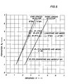
- Detectors 22 and 23 yield photoelectric ratios, R S and R L , respectively, which can be converted into P e values using relationships derived in known P e test formations.
- Fig. 6 illustrates R S and R L versus known P e for selected sand, dolomite, and limestone test formations, with fresh water boreholes and no mudcake or standoff. Data are shown for both 6 and 10 inch diameter boreholes in the limestone formations.
- the R to P e conversion relation is almost linear in each detector, and both R L and R S have similar dynamic ranges.
- a consistently higher ratio is observed in the short-spaced detector. This is caused by the different collimation apertures of the two detectors, and also because the short-spaced detector is more likely to observe single Compton scattered events than the long-spaced detector.
- the photoelectric signal is very short range (on the order of one inch). Therefore, the effective photoelectric "source” is located in the formation approximately opposite each detector. Hence, unlike the principle involved in density measurements, the formation pathlengths contributing to the photoelectrical signals in both detectors are similar, and the source-to-detector spacing in the tool itself is not important. Neither is the' ' source energy, since, as also mentioned earlier, it has been shown that a similar photoelectric measurement can be made using the natural gamma sources-in the formation.
- Pathlength independence is not true of the borehole components of the photoelectric signals in the two detectors, however (particularly in non-barite boreholes).
- the solid angle of the collimation aperture from the formation into each detector controls the relative photoelectric borehole sensitivity in that detector.
- a wider aperture permits longer gamma ray pathlengths in the borehole medium (mudcake or mud) prior to detection, and hence more borehole dependence.
- This effect is enhanced by the isotropic nature of the formation photoelectric gamma "source”, which emphasizes (longer) non-radial borehole pathlengths into less collimated detectors.
- a tightly collimated detector conversely, accentuates the measurement of radial (straight-in) gamma rays, which have shorter average borehole pathlengths.
- Natural gamma sources are located in the formation in the first place (casing, cement, and most borehole fluids are relatively inert), natural gamma spectroscopy also lends itself to the measurement of formation photoelectric absorption. Natural gamma based photoelectric measurements are more borehole sensitive than density tool based measurements, however, because the detectors in such tools are not usually collimated into the formation.
- the present invention has numerous advantages: Since P e measurements made with density logging tools have a very limited depth of investigation, it is desirable to have a direct indication of borehole induced errors in the observed P e values.
- the method and apparatus according to the present invention have been designed to provide this information, along with accurate and repeatable compensated density and P e measurements.
- Photoelectric ratio measurements made in each detector 22 and 23 are independently converted into P eS and P eL values.
- Extensive test formation and field log data in both barite and non-barite boreholes have been analyzed, and comparisons of the results from the present invention with natural gamma spectroscopy derived photoelectric logs have been made. These data confirm that due to collimation differences, long-spaced detector P e measurements are more influenced by borehole conditions than short-spaced detector P e measurements.
- the present invention is extremely versatile, and lends itself well to other measurements, such as neutron porosity.
- Two density measurements can be made at the same detector spacing above and below the source, but with different azimuthal and/or vertical apertures.
- the spacing and aperture compensation concepts can also be combined, with the short-spaced detector having the larger aperture, so that it is more sensitive to the borehole. Energy dependence can even be employed, since in a density measurement the scattered gamma rays from the near borehole tend to be higher in energy.
- the invention thus furnishes a new and powerful borehole compensation method and apparatus which are readily suited to the widest use in the borehole measurement of earth formation properties.
Landscapes
- Physics & Mathematics (AREA)
- High Energy & Nuclear Physics (AREA)
- Life Sciences & Earth Sciences (AREA)
- General Life Sciences & Earth Sciences (AREA)
- General Physics & Mathematics (AREA)
- Geophysics (AREA)
- Geophysics And Detection Of Objects (AREA)
- Analysing Materials By The Use Of Radiation (AREA)
- Measurement Of Radiation (AREA)
- Superconductors And Manufacturing Methods Therefor (AREA)
- Internal Circuitry In Semiconductor Integrated Circuit Devices (AREA)
- Printers Or Recording Devices Using Electromagnetic And Radiation Means (AREA)
Priority Applications (1)
| Application Number | Priority Date | Filing Date | Title |
|---|---|---|---|
| AT86304298T ATE55838T1 (de) | 1985-06-17 | 1986-06-05 | Verfahren und vorrichtung mit bohrlochkompensation. |
Applications Claiming Priority (2)
| Application Number | Priority Date | Filing Date | Title |
|---|---|---|---|
| US06/745,723 US4691102A (en) | 1985-06-17 | 1985-06-17 | Borehole compensation method and apparatus using variations in relative borehole components |
| US745723 | 1985-06-17 |
Publications (2)
| Publication Number | Publication Date |
|---|---|
| EP0206593A1 true EP0206593A1 (de) | 1986-12-30 |
| EP0206593B1 EP0206593B1 (de) | 1990-08-22 |
Family
ID=24997970
Family Applications (1)
| Application Number | Title | Priority Date | Filing Date |
|---|---|---|---|
| EP86304298A Expired - Lifetime EP0206593B1 (de) | 1985-06-17 | 1986-06-05 | Verfahren und Vorrichtung mit Bohrlochkompensation |
Country Status (7)
| Country | Link |
|---|---|
| US (1) | US4691102A (de) |
| EP (1) | EP0206593B1 (de) |
| AT (1) | ATE55838T1 (de) |
| AU (1) | AU5859386A (de) |
| CA (1) | CA1254675A (de) |
| DE (1) | DE3673575D1 (de) |
| SG (1) | SG5691G (de) |
Cited By (6)
| Publication number | Priority date | Publication date | Assignee | Title |
|---|---|---|---|---|
| EP0348260A1 (de) * | 1988-06-07 | 1989-12-27 | Schlumberger Limited | Bohrloch-Verfahren und -Vorrichtung zur Ermittlung der Kohlenstoff-/Sauerstoff-Komponenten |
| US4937446A (en) * | 1988-06-07 | 1990-06-26 | Schlumberger Technology Corporation | Carbon/oxygen well logging method and apparatus |
| US5045693A (en) * | 1988-06-07 | 1991-09-03 | Schlumberger Technology Corporation | Carbon/oxygen well logging method and apparatus |
| US5055676A (en) * | 1990-05-09 | 1991-10-08 | Schlumberger Technology Corporation | Method for determining oil and water saturation in earth formation surrounding a borehole |
| EP0379813A3 (de) * | 1988-12-08 | 1993-01-27 | Schlumberger Limited | Vorrichtung zur Messung von Erdformationen mit hoher räumlicher Auflösung |
| EP0860715A1 (de) * | 1997-02-19 | 1998-08-26 | Schlumberger Limited | Verfahren und Vorrichtung zur Messung der Formationsdichte und des photoelektrischen Faktors mit einer Mehrfachdetektoren-Gamma-Gamma-Sonde |
Families Citing this family (12)
| Publication number | Priority date | Publication date | Assignee | Title |
|---|---|---|---|---|
| US4857729A (en) * | 1988-04-22 | 1989-08-15 | Halliburton Logging Services, Inc. | Method of radioactive well logging |
| US5349184A (en) * | 1993-01-21 | 1994-09-20 | Schlumberger Technology Corporation | Method and apparatus for reducing matrix density effects on porosity measurements during epithermal neutron porosity well logging |
| DE4423780A1 (de) * | 1994-06-30 | 1996-01-04 | Klaus Dr Buckup | Fokussierhülle für Neutronendetektoren |
| US6781115B2 (en) | 2001-03-30 | 2004-08-24 | Schlumberger Technology Corporation | Subsurface radiation phenomena detection with combined and azimuthally sensitive detectors |
| US7339161B2 (en) * | 2005-02-24 | 2008-03-04 | Schlumberger Technology Corporation | Shielded pads for detecting subsurface radiation phenomena |
| US7365307B2 (en) * | 2005-02-28 | 2008-04-29 | Schlumberger Technology Corporation | Sigma/porosity tools with neutron monitors |
| US7642507B2 (en) * | 2005-02-28 | 2010-01-05 | Schlumberger Technology Corporation | Apparatus and methods for interlaced density and neutron measurements |
| US7361886B2 (en) * | 2005-02-28 | 2008-04-22 | Schlumberger Technology Corporation | Corrections of gamma-ray responses |
| US9971041B1 (en) * | 2017-11-10 | 2018-05-15 | Hunter Well Science, Inc. | Radiation sensor |
| US10921301B2 (en) * | 2019-02-21 | 2021-02-16 | Deep Isolation, Inc. | Testing subterranean water for a hazardous waste material repository |
| US11940591B2 (en) * | 2020-08-07 | 2024-03-26 | Nabors Drilling Technologies Usa, Inc. | Gamma ray logging tool with detector window |
| CN116150695B (zh) * | 2023-02-21 | 2026-02-17 | 中海油能源发展股份有限公司 | 一种钻井液漏失位置确定及漏失参数计算方法 |
Citations (3)
| Publication number | Priority date | Publication date | Assignee | Title |
|---|---|---|---|---|
| US3202822A (en) * | 1961-11-13 | 1965-08-24 | Phillips Petroleum Co | Method of determining density utilizing a gamma ray source and a pair of detectors |
| US3247384A (en) * | 1962-10-16 | 1966-04-19 | Schlumberger Well Surv Corp | Radially collimating window for welltool orienting instruments |
| US3864569A (en) * | 1970-04-14 | 1975-02-04 | Schlumberger Technology Corp | Well logging processing method and apparatus |
Family Cites Families (5)
| Publication number | Priority date | Publication date | Assignee | Title |
|---|---|---|---|---|
| US3321625A (en) * | 1962-12-10 | 1967-05-23 | Schlumberger Technology Corp | Compensated gamma-gamma logging tool using two detectors of different sensitivities and spacings from the source |
| US3521063A (en) * | 1967-07-19 | 1970-07-21 | Schlumberger Technology Corp | Multiple gamma radiation logging technique for identifying low atomic number materials |
| US3887805A (en) * | 1970-07-29 | 1975-06-03 | Schlumberger Ltd | Measuring apparatus |
| US3858037A (en) * | 1973-01-18 | 1974-12-31 | Schlumberger Technology Corp | Well-logging measuring apparatus and method |
| US4529877A (en) * | 1982-11-24 | 1985-07-16 | Halliburton Company | Borehole compensated density logs corrected for naturally occurring gamma rays |
-
1985
- 1985-06-17 US US06/745,723 patent/US4691102A/en not_active Expired - Fee Related
-
1986
- 1986-06-05 DE DE8686304298T patent/DE3673575D1/de not_active Expired - Fee Related
- 1986-06-05 AT AT86304298T patent/ATE55838T1/de not_active IP Right Cessation
- 1986-06-05 EP EP86304298A patent/EP0206593B1/de not_active Expired - Lifetime
- 1986-06-12 AU AU58593/86A patent/AU5859386A/en not_active Abandoned
- 1986-06-17 CA CA000511758A patent/CA1254675A/en not_active Expired
-
1991
- 1991-02-07 SG SG56/91A patent/SG5691G/en unknown
Patent Citations (3)
| Publication number | Priority date | Publication date | Assignee | Title |
|---|---|---|---|---|
| US3202822A (en) * | 1961-11-13 | 1965-08-24 | Phillips Petroleum Co | Method of determining density utilizing a gamma ray source and a pair of detectors |
| US3247384A (en) * | 1962-10-16 | 1966-04-19 | Schlumberger Well Surv Corp | Radially collimating window for welltool orienting instruments |
| US3864569A (en) * | 1970-04-14 | 1975-02-04 | Schlumberger Technology Corp | Well logging processing method and apparatus |
Cited By (7)
| Publication number | Priority date | Publication date | Assignee | Title |
|---|---|---|---|---|
| EP0348260A1 (de) * | 1988-06-07 | 1989-12-27 | Schlumberger Limited | Bohrloch-Verfahren und -Vorrichtung zur Ermittlung der Kohlenstoff-/Sauerstoff-Komponenten |
| US4937446A (en) * | 1988-06-07 | 1990-06-26 | Schlumberger Technology Corporation | Carbon/oxygen well logging method and apparatus |
| US5045693A (en) * | 1988-06-07 | 1991-09-03 | Schlumberger Technology Corporation | Carbon/oxygen well logging method and apparatus |
| EP0379813A3 (de) * | 1988-12-08 | 1993-01-27 | Schlumberger Limited | Vorrichtung zur Messung von Erdformationen mit hoher räumlicher Auflösung |
| US5055676A (en) * | 1990-05-09 | 1991-10-08 | Schlumberger Technology Corporation | Method for determining oil and water saturation in earth formation surrounding a borehole |
| EP0860715A1 (de) * | 1997-02-19 | 1998-08-26 | Schlumberger Limited | Verfahren und Vorrichtung zur Messung der Formationsdichte und des photoelektrischen Faktors mit einer Mehrfachdetektoren-Gamma-Gamma-Sonde |
| US5841135A (en) * | 1997-02-19 | 1998-11-24 | Schlumberger Technology Corporation | Method and apparatus for measuring formation density and the formation photo-electric factor with a multi-detector gamma-gamma tool |
Also Published As
| Publication number | Publication date |
|---|---|
| ATE55838T1 (de) | 1990-09-15 |
| CA1254675A (en) | 1989-05-23 |
| AU5859386A (en) | 1986-12-24 |
| DE3673575D1 (de) | 1990-09-27 |
| US4691102A (en) | 1987-09-01 |
| EP0206593B1 (de) | 1990-08-22 |
| SG5691G (en) | 1991-04-05 |
Similar Documents
| Publication | Publication Date | Title |
|---|---|---|
| EP0206593B1 (de) | Verfahren und Vorrichtung mit Bohrlochkompensation | |
| US6207953B1 (en) | Apparatus and methods for determining gas saturation and porosity of a formation penetrated by a gas filled or liquid filled borehole | |
| US7642507B2 (en) | Apparatus and methods for interlaced density and neutron measurements | |
| AU737237B2 (en) | Method for determining formation density and formation photo-electric factor with a multi-detector-gamma-ray tool | |
| US5525797A (en) | Formation density tool for use in cased and open holes | |
| EP1651985B1 (de) | Integriertes logging-werkzeug für ein bohrloch | |
| CA2228991C (en) | Multi-detector gamma-gamma for measuring formation density | |
| US5627368A (en) | Four-detector formation-density tool for use in cased and open holes | |
| US4342911A (en) | Focused nuclear interface survey instrument and method of determining density changes in mining and storage wells | |
| US6738720B2 (en) | Apparatus and methods for measurement of density of materials using a neutron source and two spectrometers | |
| IE903132A1 (en) | Nuclear spectroscopy signal stabilization and calibration¹method and apparatus | |
| US5012091A (en) | Production logging tool for measuring fluid densities | |
| EP0184898B1 (de) | Verfahren zur Durchführung einer Bohrlochuntersuchung mittels zweier Strahlungsdetektoren | |
| US20140034822A1 (en) | Well-logging apparatus including axially-spaced, noble gas-based detectors | |
| US6927390B2 (en) | Gamma ray spectroscopy logging-while-drilling system | |
| EP0267075B1 (de) | Verfahren zur Ermittlung von Charakteristika in einem Bohrloch mit erhöhter vertikaler Auflösung | |
| US7361886B2 (en) | Corrections of gamma-ray responses | |
| US4464930A (en) | Method for identifying complex lithologies in a subsurface formation | |
| US2933609A (en) | Radioactivity well surveying | |
| Wraight et al. | Combination formation density and neutron porosity measurements while drilling | |
| US9052404B2 (en) | Well-logging apparatus including azimuthally-spaced, noble gas-based detectors | |
| US4578580A (en) | Gamma spectrum porosity measurement | |
| US4698499A (en) | Quantitative evaluation of uranium ore zones | |
| US4825071A (en) | Gamma ray borehole logging method and apparatus having compensation for borehole attenuation effects | |
| Maranuk et al. | Applications of a unique spectral azimuthal gamma ray tool to unconventional reservoirs |
Legal Events
| Date | Code | Title | Description |
|---|---|---|---|
| PUAI | Public reference made under article 153(3) epc to a published international application that has entered the european phase |
Free format text: ORIGINAL CODE: 0009012 |
|
| AK | Designated contracting states |
Kind code of ref document: A1 Designated state(s): AT DE FR GB IT NL SE |
|
| 17P | Request for examination filed |
Effective date: 19870424 |
|
| 17Q | First examination report despatched |
Effective date: 19880802 |
|
| GRAA | (expected) grant |
Free format text: ORIGINAL CODE: 0009210 |
|
| AK | Designated contracting states |
Kind code of ref document: B1 Designated state(s): AT DE FR GB IT NL SE |
|
| PG25 | Lapsed in a contracting state [announced via postgrant information from national office to epo] |
Ref country code: IT Free format text: LAPSE BECAUSE OF FAILURE TO SUBMIT A TRANSLATION OF THE DESCRIPTION OR TO PAY THE FEE WITHIN THE PRE;WARNING: LAPSES OF ITALIAN PATENTS WITH EFFECTIVE DATE BEFORE 2007 MAY HAVE OCCURRED AT ANY TIME BEFORE 2007. THE CORRECT EFFECTIVE DATE MAY BE DIFFERENT FROM THE ONE RECORDED.SCRIBED TIME-LIMIT Effective date: 19900822 Ref country code: AT Effective date: 19900822 Ref country code: SE Free format text: THE PATENT HAS BEEN ANNULLED BY A DECISION OF A NATIONAL AUTHORITY Effective date: 19900822 |
|
| REF | Corresponds to: |
Ref document number: 55838 Country of ref document: AT Date of ref document: 19900915 Kind code of ref document: T |
|
| REF | Corresponds to: |
Ref document number: 3673575 Country of ref document: DE Date of ref document: 19900927 |
|
| ET | Fr: translation filed | ||
| PLBE | No opposition filed within time limit |
Free format text: ORIGINAL CODE: 0009261 |
|
| STAA | Information on the status of an ep patent application or granted ep patent |
Free format text: STATUS: NO OPPOSITION FILED WITHIN TIME LIMIT |
|
| ITTA | It: last paid annual fee | ||
| 26N | No opposition filed | ||
| PGFP | Annual fee paid to national office [announced via postgrant information from national office to epo] |
Ref country code: GB Payment date: 19920505 Year of fee payment: 7 |
|
| PGFP | Annual fee paid to national office [announced via postgrant information from national office to epo] |
Ref country code: FR Payment date: 19920609 Year of fee payment: 7 |
|
| PGFP | Annual fee paid to national office [announced via postgrant information from national office to epo] |
Ref country code: NL Payment date: 19920630 Year of fee payment: 7 |
|
| PGFP | Annual fee paid to national office [announced via postgrant information from national office to epo] |
Ref country code: DE Payment date: 19920702 Year of fee payment: 7 |
|
| PG25 | Lapsed in a contracting state [announced via postgrant information from national office to epo] |
Ref country code: GB Effective date: 19930605 |
|
| PG25 | Lapsed in a contracting state [announced via postgrant information from national office to epo] |
Ref country code: NL Effective date: 19940101 |
|
| GBPC | Gb: european patent ceased through non-payment of renewal fee |
Effective date: 19930605 |
|
| NLV4 | Nl: lapsed or anulled due to non-payment of the annual fee | ||
| PG25 | Lapsed in a contracting state [announced via postgrant information from national office to epo] |
Ref country code: FR Effective date: 19940228 |
|
| PG25 | Lapsed in a contracting state [announced via postgrant information from national office to epo] |
Ref country code: DE Effective date: 19940301 |
|
| REG | Reference to a national code |
Ref country code: FR Ref legal event code: ST |