EP0206520B1 - Bremsbetätigungsvorrichtungen - Google Patents
Bremsbetätigungsvorrichtungen Download PDFInfo
- Publication number
- EP0206520B1 EP0206520B1 EP19860303851 EP86303851A EP0206520B1 EP 0206520 B1 EP0206520 B1 EP 0206520B1 EP 19860303851 EP19860303851 EP 19860303851 EP 86303851 A EP86303851 A EP 86303851A EP 0206520 B1 EP0206520 B1 EP 0206520B1
- Authority
- EP
- European Patent Office
- Prior art keywords
- piston
- piston rod
- parking brake
- feature
- actuator
- Prior art date
- Legal status (The legal status is an assumption and is not a legal conclusion. Google has not performed a legal analysis and makes no representation as to the accuracy of the status listed.)
- Expired
Links
- 239000012530 fluid Substances 0.000 claims description 7
- 238000012423 maintenance Methods 0.000 description 2
- 241000543375 Sideroxylon Species 0.000 description 1
- 230000000694 effects Effects 0.000 description 1
- 238000009434 installation Methods 0.000 description 1
Images


Classifications
-
- B—PERFORMING OPERATIONS; TRANSPORTING
- B60—VEHICLES IN GENERAL
- B60T—VEHICLE BRAKE CONTROL SYSTEMS OR PARTS THEREOF; BRAKE CONTROL SYSTEMS OR PARTS THEREOF, IN GENERAL; ARRANGEMENT OF BRAKING ELEMENTS ON VEHICLES IN GENERAL; PORTABLE DEVICES FOR PREVENTING UNWANTED MOVEMENT OF VEHICLES; VEHICLE MODIFICATIONS TO FACILITATE COOLING OF BRAKES
- B60T17/00—Component parts, details, or accessories of power brake systems not covered by groups B60T8/00, B60T13/00 or B60T15/00, or presenting other characteristic features
- B60T17/08—Brake cylinders other than ultimate actuators
- B60T17/085—Spring loaded brake actuators
- B60T17/086—Spring loaded brake actuators with emergency release device
Definitions
- the present invention relates to a brake actuation system as described in GB-A-2.067.666 which corresponds to the pre-characterizing portion of Claim 1.
- the present invention relates to an actuator system of the type comprising an actuator controlled both by a service brake feature and a parking brake feature, the service brake feature being operable by pressure fluid and spring releasable, and the parking brake feature being spring operated to a brake-applied condition and releasable by pressure fluid.
- the spring of the parking brake feature is pneumatically or hydraulically compressed during normal service braking.
- the parking brake feature When the parking brake feature is activated, i.e. fluid pressure is released, the spring of the parking brake forces a piston in the parking brake feature towards the service brake feature so that a piston rod releasably connected to said piston, can engage and move a further piston, located in said service brake feature to compress the return spring of the service brake feature and hold the brakes applied.
- the parking brake may be released by disconnecting the piston rod from the piston in the parking brake feature, so that the spring on the service brake feature is released, thus releasing the brake.
- This releasable connection between the piston rod and the parking brake piston can take the form of a number of balls which are engaged in radial bores which extend from an axial blind bore in the piston rod to the outside surface of the piston rod.
- the balls are of larger diameter than the length of the bores so that with a cylindrical actuator rod snugly, though axially movably located in said blind bore, the balls normally project beyond the outside surface of the piston rod and engage a shoulder on the piston, to thus lock the parking brake piston and piston rod together, in the available direction of movement of the piston rod for brake operation.
- the actuator rod is held in the locking position by suitably located springs.
- the actuator rod has an annular groove in its outer surface so that when the actuator rod is moved axially in said blind bore against the suitably located springs, in the available direction of movement of the piston rod for brake operation, the balls can transfer into the annular groove so that the piston rod and parking brake piston are disconnected and the parking brake is released. Subsequent pneumatic pressurisation of the parking brake feature moves the shoulder of the parking brake piston back past the said bores so that the suitably located springs can act upon the actuator rod to move the balls back to the locked position.
- the actuator rod in the above described type of actuator system be operable via a Bowden cable and a remote lever control.
- the integrally constructed actuation system is mounted at one location and the remote lever control is mounted at a separate remote location, the flexible Bowden cable absorbing the kick-back of the released piston rod.
- this requires two separate mounting installations and a remote control.
- the aim of the present invention is to provide an actuation system of the above described type, wherein the piston rod and parking brake piston, and thus the parking brake, can be released safely by means integrally formed on the actuation system.
- an actuation system comprising an actuator controlled both by a service brake feature and a parking brake feature, the service brake feature being operably by pressure fluid and spring releasable, and the parking brake feature being spring operated to a brake-applied condition and releasable by pressure fluid, a piston in the parking brake feature being releasably connected to a piston rod which can engage and move a further piston in the service brake feature to compress a return spring in the service brake feature and hold the actuator in a brakes applied condition when the parking brake feature is spring operated to the brake-applied condition, an actuator rod being movable parallel to the axis of and relative to the piston rod, towards said further piston to release said piston from said piston rod, characterised in that a lever is pivotally mounted at a point along its length, on the said piston rod, and pivotally mounted at one end region thereof, on the actuator rod.
- the other end region of the lever is connected to one end region of an elongate flexible member, e.g. one end region of a chain.
- two pivotal levers are provided, each being pivotally connected both to the piston rod and the actuator rod, and the chain extending between the free end regions of the two levers.
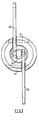
- the brake actuation system shown in Fig. 1 comprises a wedge actuator 1 to which a service brake assembly 3 is attached, a parking brake assembly 5 being secured to the service brake assembly 3.
- the service brake assembly 3 comprises a chamber 7 within which a piston 9 is movable under pneumatic pressure, against a spring 11.
- the piston 9 is connected by shaft 13 to a wedge 15 which operates the brakes (not shown) when pneumatic pressure is applied.
- the parking brake assembly 5 comprises a chamber 17 within which a piston 19 is axially movable, the piston 19 being releasably connected to a piston rod 21 which extends through a wall of chamber 17 into chamber 7 of the service brake assembly 3.
- the piston 19 is movable away from the service brake assembly chamber 7 by pneumatic pressure, whence a spring 23 is compressed.
- the chamber 17 of the parking brake assembly 5 is pressurised and the spring 23 is thus compressed; the service brake assembly 3 operating as desired, to move the wedge 15 back and forth.
- the chamber 17 of the parking brake assembly 5 is evacuated and spring 23 moves the piston 19 and piston rod 21 so that piston rod 21 engages the piston 9 in the service brake assembly 3, moving shaft 13 to operate the brakes via wedge 15.
- the chamber 17 is pressurised.
- This releasable connection between the piston rod 21 and the piston 19 basically comprises a number of balls 25 each located in one of a series of radial bores 27 formed in the piston rod 21.
- the bores 27 extend from an axially extending blind bore 29 in the piston rod 21 to the surface of the piston rod 21, and balls 25 have a larger diameter than the length of each bore 27.
- a chain release mechanism 43 is provided.
- This mechanism comprises two levers 45 which are each pivotally mounted both on the actuator rod 31 and the piston rod 21.
- a chain 47 is connected to the free end regions of the levers 45 and thus bully pulling on the chain 47 generally in direction A, the levers pivot, moving actuator rod 31 in direction B to thus release the brakes.
- the flexible chain 47 absorbs the above described kick-back and a further safeguard is that the operator moves in direction A, i.e., away from the actuation system and in the same direction as the piston rod kick-back, when operating the release mechanism.
- only one lever 45 is provided, the free end of the chain being either loose or preferably secured to a part of the integral actuation system.
- the present invention thus provides a simple and safe means for manually releasing the parking brake on, for example, a railway vehicle, wherein a brake actuation system of the above described type is installed.
Landscapes
- Engineering & Computer Science (AREA)
- Transportation (AREA)
- Mechanical Engineering (AREA)
- Braking Systems And Boosters (AREA)
- Braking Arrangements (AREA)
Claims (5)
Applications Claiming Priority (2)
| Application Number | Priority Date | Filing Date | Title |
|---|---|---|---|
| GB8513533 | 1985-05-29 | ||
| GB858513533A GB8513533D0 (en) | 1985-05-29 | 1985-05-29 | Brake actuators |
Publications (2)
| Publication Number | Publication Date |
|---|---|
| EP0206520A1 EP0206520A1 (de) | 1986-12-30 |
| EP0206520B1 true EP0206520B1 (de) | 1989-03-22 |
Family
ID=10579842
Family Applications (1)
| Application Number | Title | Priority Date | Filing Date |
|---|---|---|---|
| EP19860303851 Expired EP0206520B1 (de) | 1985-05-29 | 1986-05-21 | Bremsbetätigungsvorrichtungen |
Country Status (3)
| Country | Link |
|---|---|
| EP (1) | EP0206520B1 (de) |
| DE (1) | DE3662504D1 (de) |
| GB (1) | GB8513533D0 (de) |
Families Citing this family (2)
| Publication number | Priority date | Publication date | Assignee | Title |
|---|---|---|---|---|
| FR2934981B1 (fr) * | 2008-08-13 | 2010-09-24 | Faiveley Transp Amiens | Actionneur de frein de parking ou de secours pour frein a deverrouillage a billes |
| FR3130725B1 (fr) | 2021-12-22 | 2024-04-19 | Faiveley Transp Amiens | Système de freinage ferroviaire et véhicule ferroviaire pourvu d’un tel système |
Family Cites Families (5)
| Publication number | Priority date | Publication date | Assignee | Title |
|---|---|---|---|---|
| FR1465672A (fr) * | 1965-12-02 | 1967-01-13 | Westinghouse Freins & Signaux | Dispositif de déblocage automatique d'un frein de stationnement couplé à un freinde service à fluide sous pression |
| DE1555116A1 (de) * | 1966-07-06 | 1970-07-09 | Daimler Benz Ag | Schnelloeseeinrichtung fuer Federspeicherzylinder |
| US4080875A (en) * | 1975-07-24 | 1978-03-28 | Alexandr Ivanovich Repolovsky | Vehicle braking means |
| DE2840836A1 (de) * | 1978-09-20 | 1980-04-03 | Teves Gmbh Alfred | Federspeicher, insbesondere zur bremsbetaetigung |
| GB2067666B (en) * | 1980-01-14 | 1983-08-17 | Lucas Industries Ltd | Brake actuators |
-
1985
- 1985-05-29 GB GB858513533A patent/GB8513533D0/en active Pending
-
1986
- 1986-05-21 EP EP19860303851 patent/EP0206520B1/de not_active Expired
- 1986-05-21 DE DE8686303851T patent/DE3662504D1/de not_active Expired
Also Published As
| Publication number | Publication date |
|---|---|
| DE3662504D1 (en) | 1989-04-27 |
| EP0206520A1 (de) | 1986-12-30 |
| GB8513533D0 (en) | 1985-07-03 |
Similar Documents
| Publication | Publication Date | Title |
|---|---|---|
| CA1052299A (en) | Device for discontinuing and automatically restoring the operational function of a spring brake actuator | |
| CA1260515A (en) | Manual release and automatic reset arrangement for spring-applied air-released brake | |
| CA1166977A (en) | Hydraulic brake actuator having spring-applied back- up brake with manual release means | |
| CA2041158C (en) | Tow hook activated brake release method and apparatus | |
| US6854570B2 (en) | Brake cylinder parking brake system | |
| US3402792A (en) | Brake actuating apparatus | |
| US4550810A (en) | Disc brakes for vehicles | |
| US4544047A (en) | Spring-applied, air-released, slack-adjusting parking brake | |
| EP0206520B1 (de) | Bremsbetätigungsvorrichtungen | |
| EP0265170A2 (de) | Scheibenbremsen | |
| US4550811A (en) | Manually releasable parking brake device | |
| CA2123767C (en) | Brake actuator having collet style slack adjuster | |
| EP0073659B1 (de) | Bremsmechanismen | |
| US5601162A (en) | Spring applied automative parking brake system | |
| US3625315A (en) | Braking control means | |
| EP0217589A2 (de) | Schienenfahrzeugbremsvorrichtung | |
| EP0073549B1 (de) | Federkraft anwendende Betätigungsglieder | |
| US5112113A (en) | Tow hook activated brake release method and apparatus | |
| EP0074734B1 (de) | Betätigung für Bremsen od. dergl. | |
| US5031731A (en) | Brake actuator with slack adjuster disabling mechanism | |
| CA1171002A (en) | Cam lock slack adjuster | |
| EP0093574A1 (de) | Scheibenbremsen für Fahrzeuge | |
| CA2381857C (en) | Overload protection device for a truck-mounted brake assembly | |
| US4049088A (en) | Parking brake arrangement for a rail vehicle brake | |
| US3448836A (en) | Two way automatic brake adjuster |
Legal Events
| Date | Code | Title | Description |
|---|---|---|---|
| PUAI | Public reference made under article 153(3) epc to a published international application that has entered the european phase |
Free format text: ORIGINAL CODE: 0009012 |
|
| AK | Designated contracting states |
Kind code of ref document: A1 Designated state(s): DE FR GB IT |
|
| 17P | Request for examination filed |
Effective date: 19870319 |
|
| 17Q | First examination report despatched |
Effective date: 19880127 |
|
| GRAA | (expected) grant |
Free format text: ORIGINAL CODE: 0009210 |
|
| AK | Designated contracting states |
Kind code of ref document: B1 Designated state(s): DE FR GB IT |
|
| ITF | It: translation for a ep patent filed | ||
| REF | Corresponds to: |
Ref document number: 3662504 Country of ref document: DE Date of ref document: 19890427 |
|
| ET | Fr: translation filed | ||
| PLBE | No opposition filed within time limit |
Free format text: ORIGINAL CODE: 0009261 |
|
| STAA | Information on the status of an ep patent application or granted ep patent |
Free format text: STATUS: NO OPPOSITION FILED WITHIN TIME LIMIT |
|
| 26N | No opposition filed | ||
| ITTA | It: last paid annual fee | ||
| PGFP | Annual fee paid to national office [announced via postgrant information from national office to epo] |
Ref country code: GB Payment date: 19920429 Year of fee payment: 7 |
|
| PGFP | Annual fee paid to national office [announced via postgrant information from national office to epo] |
Ref country code: FR Payment date: 19920511 Year of fee payment: 7 |
|
| PGFP | Annual fee paid to national office [announced via postgrant information from national office to epo] |
Ref country code: DE Payment date: 19920610 Year of fee payment: 7 |
|
| REG | Reference to a national code |
Ref country code: GB Ref legal event code: 732 |
|
| REG | Reference to a national code |
Ref country code: FR Ref legal event code: TP |
|
| PG25 | Lapsed in a contracting state [announced via postgrant information from national office to epo] |
Ref country code: GB Effective date: 19930521 |
|
| ITPR | It: changes in ownership of a european patent |
Owner name: CESSIONE;SAB WABCO HOLDINGS B.V. |
|
| GBPC | Gb: european patent ceased through non-payment of renewal fee |
Effective date: 19930521 |
|
| PG25 | Lapsed in a contracting state [announced via postgrant information from national office to epo] |
Ref country code: FR Effective date: 19940131 |
|
| PG25 | Lapsed in a contracting state [announced via postgrant information from national office to epo] |
Ref country code: DE Effective date: 19940201 |
|
| REG | Reference to a national code |
Ref country code: FR Ref legal event code: ST |
|
| PG25 | Lapsed in a contracting state [announced via postgrant information from national office to epo] |
Ref country code: IT Free format text: LAPSE BECAUSE OF NON-PAYMENT OF DUE FEES;WARNING: LAPSES OF ITALIAN PATENTS WITH EFFECTIVE DATE BEFORE 2007 MAY HAVE OCCURRED AT ANY TIME BEFORE 2007. THE CORRECT EFFECTIVE DATE MAY BE DIFFERENT FROM THE ONE RECORDED. Effective date: 20050521 |