EP0206032A1 - Electrolyser with a diaphragm electrode sandwich assembly, and assembling apparatus suited therefor - Google Patents
Electrolyser with a diaphragm electrode sandwich assembly, and assembling apparatus suited therefor Download PDFInfo
- Publication number
- EP0206032A1 EP0206032A1 EP86107650A EP86107650A EP0206032A1 EP 0206032 A1 EP0206032 A1 EP 0206032A1 EP 86107650 A EP86107650 A EP 86107650A EP 86107650 A EP86107650 A EP 86107650A EP 0206032 A1 EP0206032 A1 EP 0206032A1
- Authority
- EP
- European Patent Office
- Prior art keywords
- thread
- diaphragm
- electrolyser
- threads
- cell frame
- Prior art date
- Legal status (The legal status is an assumption and is not a legal conclusion. Google has not performed a legal analysis and makes no representation as to the accuracy of the status listed.)
- Granted
Links
- 239000004033 plastic Substances 0.000 claims abstract description 7
- 239000003792 electrolyte Substances 0.000 claims description 2
- -1 polytetrafluoroethylene Polymers 0.000 claims description 2
- 229920001343 polytetrafluoroethylene Polymers 0.000 claims description 2
- 239000004810 polytetrafluoroethylene Substances 0.000 claims description 2
- 238000007789 sealing Methods 0.000 abstract 1
- 239000007789 gas Substances 0.000 description 11
- 238000005868 electrolysis reaction Methods 0.000 description 8
- 238000005260 corrosion Methods 0.000 description 4
- 230000007797 corrosion Effects 0.000 description 4
- XLYOFNOQVPJJNP-UHFFFAOYSA-N water Substances O XLYOFNOQVPJJNP-UHFFFAOYSA-N 0.000 description 3
- 239000002184 metal Substances 0.000 description 2
- 229910052751 metal Inorganic materials 0.000 description 2
- 229910000480 nickel oxide Inorganic materials 0.000 description 2
- GNRSAWUEBMWBQH-UHFFFAOYSA-N oxonickel Chemical compound [Ni]=O GNRSAWUEBMWBQH-UHFFFAOYSA-N 0.000 description 2
- 230000015572 biosynthetic process Effects 0.000 description 1
- 230000000903 blocking effect Effects 0.000 description 1
- 239000004035 construction material Substances 0.000 description 1
- 150000004677 hydrates Chemical class 0.000 description 1
- 239000000463 material Substances 0.000 description 1
- 150000002739 metals Chemical class 0.000 description 1
- 238000000034 method Methods 0.000 description 1
- 229920002492 poly(sulfone) Polymers 0.000 description 1
- 239000000126 substance Substances 0.000 description 1
Images


Classifications
-
- C—CHEMISTRY; METALLURGY
- C25—ELECTROLYTIC OR ELECTROPHORETIC PROCESSES; APPARATUS THEREFOR
- C25B—ELECTROLYTIC OR ELECTROPHORETIC PROCESSES FOR THE PRODUCTION OF COMPOUNDS OR NON-METALS; APPARATUS THEREFOR
- C25B13/00—Diaphragms; Spacing elements
-
- C—CHEMISTRY; METALLURGY
- C25—ELECTROLYTIC OR ELECTROPHORETIC PROCESSES; APPARATUS THEREFOR
- C25B—ELECTROLYTIC OR ELECTROPHORETIC PROCESSES FOR THE PRODUCTION OF COMPOUNDS OR NON-METALS; APPARATUS THEREFOR
- C25B9/00—Cells or assemblies of cells; Constructional parts of cells; Assemblies of constructional parts, e.g. electrode-diaphragm assemblies; Process-related cell features
- C25B9/17—Cells comprising dimensionally-stable non-movable electrodes; Assemblies of constructional parts thereof
- C25B9/19—Cells comprising dimensionally-stable non-movable electrodes; Assemblies of constructional parts thereof with diaphragms
Definitions
- the frame 13 As a guide for the frame 13 relative to the electrode over which the thread is stretched, e.g. the mounting bolts of a cell block are used.
Landscapes
- Chemical & Material Sciences (AREA)
- Engineering & Computer Science (AREA)
- Chemical Kinetics & Catalysis (AREA)
- Electrochemistry (AREA)
- Materials Engineering (AREA)
- Metallurgy (AREA)
- Organic Chemistry (AREA)
- Electrolytic Production Of Non-Metals, Compounds, Apparatuses Therefor (AREA)
- Electrodes For Compound Or Non-Metal Manufacture (AREA)
- Adhesives Or Adhesive Processes (AREA)
- Electrochromic Elements, Electrophoresis, Or Variable Reflection Or Absorption Elements (AREA)
Abstract
Bei einem Elektrolyseur mit Diaphragma-Elektroden-Sandwichanordnung werden zwischen Diaphragma (1) und Elektrode (6) dünne Kunststoffäden (4) von 50-500 µm Fadenstärke vorgesehen, die sich in Gasabgaberichtung erstrecken und in einem Abstand von etwa 5-50 mm voneinander angeordnet sind. Diese Parallelfäden sind vorzugsweise am Zellrahmen festgelegt, insbesondere in einer Nut mittels eines Drahtes festgeklemmt. Für die Montage solcher Fäden eignet sich ein auf den Zellrahmen aufzupassender Montagerahmen mit einer festen Rollenleiste und einer beweglichen Rollenleiste, welch letztere an Führungen beweglich ist, die parallel zur Gasabgaberichtung verlaufen. Der meanderförmig um die Rollen der festen und der beweglichen Leiste herumgeführte Faden bespannt so haufenartig die Elektrodenfläche, und er wird insbesondere in der Zellrahmennut festgeklemmt und dann abgeschnitten, so daß bei der abschliessenden Montage der Zelle keine Dichtprobleme auftreten können.In an electrolyser with a diaphragm-electrode sandwich arrangement, thin plastic threads (4) with a thread thickness of 50-500 µm are provided between the diaphragm (1) and the electrode (6), which extend in the gas discharge direction and are arranged at a distance of about 5-50 mm from one another are. These parallel threads are preferably fixed to the cell frame, in particular clamped in a groove by means of a wire. A mounting frame to be fitted onto the cell frame with a fixed roller bar and a movable roller bar is suitable for the assembly of such threads, the latter being movable on guides which run parallel to the gas discharge direction. The thread meandering around the rollers of the fixed and the movable bar covers the electrode surface in heaps, and it is clamped in particular in the cell frame groove and then cut off, so that no sealing problems can occur during the final assembly of the cell.
Description
Die Erfindung bezieht sich auf einen Elektrolyseur mit einer Diaphragma-Elektroden-Sandwichanordnung mit einem formstabilen, elektrisch isolierenden Diaphragma und durchlässigen Elektroden sowie auf eine dafür geeignete Montageeinrichtung.The invention relates to an electrolyzer with a diaphragm-electrode sandwich arrangement with a dimensionally stable, electrically insulating diaphragm and permeable electrodes, and to a mounting device suitable therefor.
Elektrolyseure bestehen aus einer oder insbesondere mehreren zu einem Zellenblock zusammengefaßten Elektrolysezellen. Die einzelne Zelle wird durch Begrenzungsplatten oder (bipolare) Trennplatten gebildet, die eine Elektrolysekammer begrenzen, welche von einem Diaphragma in Anoden- und Kathodenkammer getrennt wird. Anode und Kathode können sandwichartig am Diaphragma anliegen, soweit dieses nicht selbst elektrisch leitend ist. Üblicherweise besteht jedoch ein Abstand von etwa 1 bis 3 mm zum Diaphragma.Electrolysers consist of one or more electrolytic cells combined to form a cell block. The individual cell is formed by boundary plates or (bipolar) separating plates which delimit an electrolysis chamber which is separated by a diaphragm in the anode and cathode chambers. Anode and cathode can be sandwiched on the diaphragm, provided that it is not itself electrically conductive. Usually, however, there is a distance of about 1 to 3 mm from the diaphragm.
Von besonderem technischen Interesse sind derzeit Elektrolyseure für die alkalische Elektrolyse, insbesondere Wasserelektrolyse, auf die somit in der vorliegenden Beschreibung besonders Bezug genommen wird.Electrolysers for alkaline electrolysis, in particular water electrolysis, are currently of particular technical interest and are therefore referred to particularly in the present description.
Für die alkalische Wasserelektrolyse wurde von der Anmelderin eine Sandwichanordnung aus einem porösen, elektrisch nichtleitenden Oxiddiaphragma und beidseits anliegenden aktiven Elektroden entwickelt (DE-OSen 29 27 566, 30 31 064 und 33 18 758), das hier als besonderes Beispiel zur Erläuterung der Erfindung dienen soll.The applicant developed a sandwich arrangement for the alkaline water electrolysis Developed a porous, electrically non-conductive oxide diaphragm and active electrodes on both sides (DE-OSen 29 27 566, 30 31 064 and 33 18 758), which is intended to serve as a special example to explain the invention.
Solche Diaphragmen auf Nickeloxidbasis besitzen eine ausgezeichnete chemische Beständigkeit in heißer Lauge, hervorragende Trenneigenschaften hinsichtlich der Produktgase (02 und H2 bei der Wasserelektrolyse) sowie elektrisch isolierende Eigenschaften, die einen unmittelbaren Kontakt der Elektroden mit dem Diaphragma ("Nullabstand") gestatten.Such diaphragms based on nickel oxide have excellent chemical resistance in hot lye, excellent separating properties with regard to the product gases (0 2 and H 2 in water electrolysis) and electrically insulating properties which allow direct contact of the electrodes with the diaphragm ("zero distance").
Mit solchen Elektroden mit Nullabstand zum Diaphragma wird eine bestmögliche Wirtschaftlichkeit der Elektrolyse in Anbetracht geringst möglicher Zellspannungen erreicht.With such electrodes with zero distance to the diaphragm, the best possible economy of the electrolysis is achieved in view of the lowest possible cell voltages.
Ein solches Diaphragma-Elektroden-Sandwich hat allerdings einen Nachteil: Das Diaphragma bleibt nur dann funktionsfähig, wenn sich an den Elektroden keine Ablagerungen bilden, die sich dann weiter in das in unmittelbarer Nähe (Nullabstand) befindliche Diaphragma fortpflanzen können. Das gesamte Zellsystem samt Peripherie muß also sehr korrosionsbeständig sein: Anderenfalls würden sich Korrosionsprodukte entweder kathodisch als Metalle oder anodisch als Oxidhydrate abscheiden und von den Elektroden in das Diaphragma hinein übertreten und dieses zusetzen oder sogar zu Kurzschlüssen führen. In der Praxis ist es nun jedoch sehr schwer oder doch zumindest sehr kostspielig, einen korrosionsfreien Zustand aufrechtzuerhalten.However, such a diaphragm-electrode sandwich has one disadvantage: the diaphragm only remains functional if no deposits form on the electrodes, which can then propagate further into the diaphragm located in the immediate vicinity (zero distance). The entire cell system, including its periphery, must therefore be very corrosion-resistant: Otherwise, corrosion products would deposit either cathodically as metals or anodically as oxide hydrates and from the electrodes into the diaphragm violate and clog it or even lead to short circuits. In practice, however, it is very difficult or at least very expensive to maintain a corrosion-free state.
D.h., die einerseits energetisch günstige und damit wirtschaftliche Verminderung der Elektrodenabstände ist mit dem Zwang zu kostspieligen Anlagen verbunden, während die konstruktiv billigere mit merklichem Abstand Diaphragma-Elektroden arbeitende Lösung energetisch nachteilig ist.In other words, the energy-saving and thus economical reduction of the electrode spacing on the one hand is associated with the need for expensive systems, while the structurally cheaper solution working with a noticeable distance between the diaphragm electrodes is energetically disadvantageous.
Es ist daher die Aufgabe der Erfindung, hier Abhilfe zu schaffen, d.h. eine konstruktive Lösung zu finden, bei der die Energieverluste aufgrund des Abstandes Diaphragma-Elektroden gering sind, aber trotzdem für Zelle und Peripherie Konstruktionsmaterialien verwendet werden können, die bei tragbarem Preis einigermaßen korrosionsbeständig sind, ohne jedoch jede Korrosion ausschließen zu müssen.It is therefore the object of the invention to remedy this, i.e. to find a constructive solution in which the energy losses due to the distance between the diaphragm electrodes are small, but nevertheless construction materials can be used for the cell and periphery, which are reasonably corrosion-resistant at a reasonable price, without however having to rule out any corrosion.
Dieses Ziel wird gemäß der Erfindung erreicht durch dünne, sich in Gasabgaberichtung erstreckende Kunststoff-Fäden mit 5 bis 50 mm Fadenzwischenraum und einer Fadenstärke von 50 bis 500 um zwischen Diaphragma und Elektrode. Bevorzugte Fadenzwischenräume liegen zwischen 10 und 20 mm, und Fadenstärken um etwa 200 pm sind besonders zweckmäßig.This aim is achieved according to the invention by thin plastic threads extending in the gas discharge direction with 5 to 50 mm thread space and a thread thickness of 50 to 500 μm between the diaphragm and the electrode. Preferred spaces between the threads are between 10 and 20 mm, and thread thicknesses of around 200 μm are particularly expedient.
Die Kunststoffäden müssen selbstverständlich unter Elektrolysebedingungen beständig sein und bestehen insbesondere aus Polytetrafluoräthylen oder auch aus anderen geeigneten beständigen Kunststoffmaterialien, wie z.B. Polysulfon.The plastic threads must of course be stable under electrolysis conditions and consist in particular of polytetrafluoroethylene or also of other suitable resistant plastic materials such as polysulfone.
Durch den Verlauf in Gasabgaberichtung kann vermieden werden, daß sich beständig sperrende Gaspolster zwischen dem Diaphragma und den Elektroden ausbilden, die den wirtschaftlichen Betrieb des Elektrolyseurs beeinträchtigen können.The course in the direction of gas discharge can prevent the formation of permanently blocking gas cushions between the diaphragm and the electrodes, which can impair the economical operation of the electrolyzer.
Die Art der Anbringung der Fäden, die in (bei Zellbetrieb) Gasabgaberichtung verlaufen, kann grundsätzlich auf beliebige Weise erreicht werden, da der Kontakt mit den angrenzenden Elementen (Diaphragma und Elektroden) für ein Weiterbestehen der einmal erreichten Anordnung sorgt. Besonders zweckmäßig ist jedoch eine Festlegung der Fäden am Zellrahmen, insbesondere in einer Nut desselben, die speziell möglichst unmittelbar benachbart zur Elektrolytkammer vorgesehen ist.The way of attaching the threads, which run in the gas discharge direction (in the case of cell operation), can in principle be achieved in any way, since the contact with the adjacent elements (diaphragm and electrodes) ensures that the arrangement which has been achieved once remains. However, it is particularly expedient to fix the threads on the cell frame, in particular in a groove thereof, which is specifically provided as directly as possible adjacent to the electrolyte chamber.
In einer solchen Nut können die Fadenenden mittels eines dünnen Drahtes oder Drahtringes festgeklemmt werden.The thread ends can be clamped in such a groove by means of a thin wire or wire ring.
Als besonders zweckmäßig erweist sich eine Montagevorrichtung für die Fäden, wie sie aus der nachfolgenden Beschreibung von Ausführungsbeispielen hervorgeht, die auf die angefügten Zeichnungen Bezug nimmt; es zeigen schematisch:
- Figur 1 den Aufbau eines erfindungsgemäßen Diaphragma-Elektroden-Sandwich's im Schnitt quer zur Gasabgaberichtung;
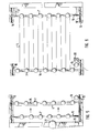
Figur 2 in Gasabgaberichtung gespannte Fäden während der Montage;- Figur 3 den mit Nuten versehenen Zellrahmen vor der Fadenmontage (im Schnitt);
Figur 4 einen in der Rahmennut festgelegten Faden zwischen Diaphragma und Elektrode vor dem Zusammenschluß der Zelle (vergrößerter Ausschnitt) und Figuren- 5 bis 7 unterschiedliche Phasen der Fadenmontage.
- Figure 1 shows the structure of a diaphragm-electrode sandwich according to the invention in section transverse to the gas discharge direction;
- Figure 2 threads tensioned in the gas discharge direction during assembly;
- Figure 3 shows the grooved cell frame before thread assembly (in section);
- 4 shows a thread fixed in the frame groove between the diaphragm and the electrode before the cell is joined (enlarged section) and the figures
- 5 to 7 different phases of thread assembly.
Gemäß Fig. 1 wird ein elektrisch isolierendes formstabiles Diaphragma 1, das insbesondere aus porösem Nickeloxid 2 auf einen gerüstgebenden Träger 3 besteht, durch Fäden 4 aus einem unter Elektrolysebedingungen beständigen Kunststoff unter Bildung eines Abstandes 5 von einer durchlässigen Elektrode 6 getrennt, die insbesondere durch eine aktivierte Lochblechelektrode gebildet wird, aber auch eine Streckmetallelektrode, Jalousieelektrode oder auch eine poröse aktivierte Elektrode sein kann.1, an electrically insulating, dimensionally stable diaphragm 1, which consists in particular of
Die Fäden 4 verlaufen in Gasabgaberichtung, so daß das an der Elektrodenvorderseite gebildete Gas ungehindert zur Gassammelleitung des Elektrolyseurs hin entweichen kann, ohne daß Gaspolster entstehen können.The
Die angegebenen Abmessungen sind als Beispiel zu verstehen und können nach Bedarf variiert werden.The dimensions given are to be understood as examples and can be varied as required.
Solche Kunststoffäden 4 werden zweckmäßigerweise, wie in Fig. 2 angedeutet ist, mit Hilfe von versetzten Leitrollen 7, 7', über die der Faden 4 meanderförmig hin- und herläuft, über den Elektroden 6 ausgespannt und in einer Nut 8 (s. Fig. 3) mit einem über die Fäden gelegten und in die Nut gepreßten (z.B. gehämmerten) Draht oder Drahtring 9 festgeklemmt. Die überstehenden Fadenenden (jenseits der Nut 8) werden zweckmäßigerweise weggeschnitten, bevor unter Aufbringung des Diaphragmas 1 die Zelle durch Zusammenspannen des Zellrahmens 10, der die bipolare Platte 11 umfaßt, fertigmontiert wird.Such
Fig. 4 zeigt die Anordnung von Zellrahmen 10, Elektrode 6, Faden 4 und Diaphragma 1 mit Zell-und Diaphragmadichtung 12 in einem Ausschnitt in vergrößerter Form.4 shows the arrangement of
Eine für die Montage des erfindungsgemäß vorgesehenen Fadens 4 besonders geeignete Vorrichtung ist in den Fig. 5 - 7 angedeutet:
- Die daraus ersichtliche Vorrichtung umfaßt einen
Rahmen 13 mit einerfesten Rollenleiste 14 und einerbeweglichen Rollenleiste 15 mit zueinanderversetzten Gleitrollen 7, 7', über die derFaden 4 läuft. Diebewegliche Leiste 15 wird durchFührungen 16, 16' parallel zurLeiste 14 gehalten.
- The device evident therefrom comprises a
frame 13 with afixed roller bar 14 and amovable roller bar 15 with mutuallyoffset sliding rollers 7, 7 ', over which thethread 4 runs. Themovable bar 15 is held parallel to thebar 14 byguides 16, 16 '.
Die bewegliche Leiste 15 kann über die feste Leiste 14 hinweg bewegt werden (s. insbesondere Fig. 7), und ihre Rollen 7' sind versetzt zu den Rollen 7 der festen Leiste hängend angeordnet,The
so daß sich die Rollen 7, 7' praktisch in einer Ebene befinden.so that the
Wie in Fig. 5 angedeutet ist, wird der zunächst nur über die Rollen 7 der festen Leiste 14 geführte Faden bei Verschiebung der beweglichen Leiste von den kammartig dazwischen greifenden Rollen 7' mitgenommen und harfenartig über die Fläche der darunter befindlichen Elektrode (oder ggf. des darunter befindlichen Diaphragmas) ausgezogen. Während dieses Vorganges soll der Faden noch einen geringen Abstand zu dem darunter befindlichen Element (Elektrode oder auch evtl. Diaphragma) haben, und er wird dann nach Anschlag der beweglichen Leiste 15 (bei 17) oder deren Festlegung in gewünschter Entfernung zur festen Leiste z.B. mit Klemmschrauben (wodurch eine Anpassung der Vorrichtung an unterschiedliche Zellengrößen erreicht wird) durch ein- oder beidseitige Absenkung des Rahmens mit der darunter befindlichen Elektrode (oder auch evtl. dem Diaphragma) in Kontakt gebracht.As indicated in Fig. 5, the thread, which is initially only guided over the
Die Anordnung entspricht dann der Fig. 2 - allerdings noch ohne Klemmdraht oder Klemmring, der dann aufgesetzt und durch Anhämmern o.dgl. angepreßt wird, woraufhin die über die Nut nach außen hinausragenden Fadenteile abgeschnitten werden sollten.The arrangement then corresponds to FIG. 2 - but still without a clamping wire or clamping ring, which is then attached and the like by hammering. is pressed, whereupon the thread parts projecting outwards beyond the groove should be cut off.
Als Führung für den Rahmen 13 relativ zur Elektrode, über die der Faden gespannt wird, können z.B. die Montagebolzen eines Zellenblocks dienen.As a guide for the
Die durch Spreizung (bzw. Voneinanderentfernung) durch Rollenleisten 14, 15 voneinander harfenartig ausgespannte Faden 4 läuft insbesondere von einer Vorratsrolle (21) ab, die vom Rahmen 13 gehalten werden kann.The harp-like by spreading (or distance from each other) by
Das freie Ende des Fadens wird bei 18 festgelegt, beispielsweise mit Hilfe einer Klemme festgeklemmt, und der Faden läuft über eine Spannrolle 19 zur Vorratsrolle (21).The free end of the thread is fixed at 18, for example clamped with the aid of a clamp, and the thread runs over a
Für die Passung des Montagerahmens 13 auf den Zellrahmen 10 können entsprechende Paßelemente, wie in 20 angedeutet, vorgesehen sein, die etwa um die Montagebolzen des Zellenblocks greifen und somit eine einfache Ausrichtung des Montagerahmens 13 ermöglichen.For fitting the
Für das Ausspannen des Fadens 4 über sehr großflächigen Elektroden kann der (bei der Montage zusammenhängende) Faden 4 selbstverständlich in eine Serie von Fäden unterteilt werden, die von einer Mehrzahl von Vorratsrollen ablaufen, so daß von einer einzelnen Vorratsrolle jeweils nur ein um z.B. 10 Rollen laufendes Fadenstück abgezogen wird. Dieser Mehrzahl von Vorratsrollen sind dann eine entsprechende Anzahl von Spannrollen zugeordnet, und die jeweiligen Fadenenden der Fadenstücke werden ebenso durch eine Mehrzahl von Festlegungselementen 18 festgelegt. Alternativ kann die Überspannung größerer Flächen schrittweise erfolgen durch zeitlich aufeinanderfolgende (Teil)Ausspannung von jeweils nur eines um z.B. 10 Rollen laufenden Fadenstücks.For unclamping the
Der einen Minimalabstand zwischen Elektrode und Diaphragma gewährleistende Faden 4 wird insbesondere anodenseitig vorgesehen, da ein gewisser Minimalabstand zwischen Anode und Diaphragma besonders wichtig ist. Üblicherweise wird man jedoch den Faden auch beidseits des Diaphragmas, also sowohl kathoden- als auch anodenseitig ausspannen.The
Claims (12)
dadurch gekennzeichnet , daß die Fäden (4) aus Polytetrafluoräthylen bestehen.4. Electrolyser according to one of the preceding claims,
characterized in that the threads (4) consist of polytetrafluoroethylene.
dadurch gekennzeichnet , daß die Fäden (4) zwischen den Elektroden (6) und dem Diaphragma (1) am Zellrahmen (10) festgelegt sind.5. electrolyser according to one of the preceding claims,
characterized in that the threads (4) are fixed between the electrodes (6) and the diaphragm (1) on the cell frame (10).
dadurch gekennzeichnet , daß die Fadenenden in einer Nut (8) im Zellrahmen (10) eingeklemmt sind.6. electrolyser according to claim 5,
characterized , that the thread ends are clamped in a groove (8) in the cell frame (10).
gekennzeichnet durch eine zur Elektrolytkammer unmittelbar benachbarte Nut (8).7. electrolyser according to claim 6,
characterized by a groove (8) immediately adjacent to the electrolyte chamber.
gekennzeichnet durch einen auf den Zellrahmen (10) aufzupassenden Montagerahmen (13) mit einer festen Rollenleiste (14) auf einer Seite des Zellrahmens und Seitenführungen (16, 16'), die parallel zur Gasabgaberichtung der montierten Zelle verlaufen, für eine über die Zellrahmenfläche verschiebliche Rollenleiste (15) mit zur festen Leiste versetzten Rollen (7') und mit zumindest einem Mittel (18) zur Festlegung zumindest eines Fadenendes und einer entsprechenden Anzahl von Spannrollen (19) für das jeweils andere Ende des meanderförmig über die Rollen geführten Fadens (4).9. Device for assembling the threads in a sandwich arrangement according to one of claims 5 to 8,
characterized by a mounting frame (13) to be fitted onto the cell frame (10) with a fixed roller bar (14) on one side of the cell frame and side guides (16, 16 '), which run parallel to the gas discharge direction of the assembled cell, for one which can be moved over the cell frame surface Roller bar (15) with rollers (7 ') offset from the fixed bar and with at least one means (18) for fixing at least one thread end and a corresponding number of tensioning rollers (19) for the respective other end of the thread (4 ).
gekennzeichnet durch zumindest eine Vorratsrolle, von welcher der an dem einen Ende festgelegte Faden abläuft.10. The device according to claim 9,
marked by at least one supply roll from which the thread fixed at one end runs off.
Applications Claiming Priority (2)
| Application Number | Priority Date | Filing Date | Title |
|---|---|---|---|
| DE8517106U DE8517106U1 (en) | 1985-06-12 | 1985-06-12 | Diaphragm for alkaline electrolysis |
| DE8517106U | 1985-06-12 |
Publications (2)
| Publication Number | Publication Date |
|---|---|
| EP0206032A1 true EP0206032A1 (en) | 1986-12-30 |
| EP0206032B1 EP0206032B1 (en) | 1989-12-13 |
Family
ID=6782044
Family Applications (1)
| Application Number | Title | Priority Date | Filing Date |
|---|---|---|---|
| EP86107650A Expired EP0206032B1 (en) | 1985-06-12 | 1986-06-05 | Electrolyser with a diaphragm electrode sandwich assembly, and assembling apparatus suited therefor |
Country Status (8)
| Country | Link |
|---|---|
| US (1) | US4773982A (en) |
| EP (1) | EP0206032B1 (en) |
| JP (1) | JPS6244587A (en) |
| BR (1) | BR8602715A (en) |
| CA (1) | CA1327773C (en) |
| DE (2) | DE8517106U1 (en) |
| NO (1) | NO165600C (en) |
| ZA (1) | ZA864358B (en) |
Cited By (2)
| Publication number | Priority date | Publication date | Assignee | Title |
|---|---|---|---|---|
| EP0340820A1 (en) * | 1988-05-05 | 1989-11-08 | Metallgesellschaft Ag | Electrolyser |
| GB2240988A (en) * | 1986-12-19 | 1991-08-21 | Olin Corp | Membrane electrolytic cell incorporating separator |
Families Citing this family (4)
| Publication number | Priority date | Publication date | Assignee | Title |
|---|---|---|---|---|
| US6027620A (en) * | 1995-11-03 | 2000-02-22 | Huron Tech Corp | Filter press electrolyzer |
| CN102124146B (en) * | 2008-06-16 | 2014-07-30 | 威廉·R.·理查兹 | Alkaline electrolyzer |
| US9222178B2 (en) | 2013-01-22 | 2015-12-29 | GTA, Inc. | Electrolyzer |
| US8808512B2 (en) | 2013-01-22 | 2014-08-19 | GTA, Inc. | Electrolyzer apparatus and method of making it |
Citations (3)
| Publication number | Priority date | Publication date | Assignee | Title |
|---|---|---|---|---|
| FR2460341A1 (en) * | 1979-07-04 | 1981-01-23 | Creusot Loire | Electrolysis cell for mfg. gas, esp. hydrogen and oxygen from water - where nickel fabric diaphragm is supported by grid of insulating beads |
| FR2475066A1 (en) * | 1980-02-06 | 1981-08-07 | Cem Comp Electro Mec | Expanded spacer used between two parallel surfaces - esp. expanded polymer foil used between electrodes in electrolyser mfg. hydrogen in high yield |
| EP0170051A2 (en) * | 1984-06-30 | 1986-02-05 | Forschungszentrum Jülich Gmbh | Diaphragm for alkaline electrolysis, and its manufacturing process |
Family Cites Families (8)
| Publication number | Priority date | Publication date | Assignee | Title |
|---|---|---|---|---|
| US3674767A (en) * | 1967-07-14 | 1972-07-04 | Nat Res Dev | Novel polymeric materials containing triazinyl groups |
| US4174259A (en) * | 1976-09-24 | 1979-11-13 | Hooker Chemicals & Plastics Corp. | Electrolytic cell structure and method of assembly |
| JPS5365275A (en) * | 1976-11-24 | 1978-06-10 | Asahi Glass Co Ltd | Structure of electrode chamber |
| DE2927566C2 (en) * | 1979-07-07 | 1986-08-21 | Kernforschungsanlage Jülich GmbH, 5170 Jülich | Diaphragm for alkaline electrolysis, process for producing the same and its use |
| DE3031064C2 (en) * | 1980-08-16 | 1986-09-04 | Kernforschungsanlage Jülich GmbH, 5170 Jülich | Porous oxide diaphragm for alkaline electrolysis and its use |
| US4377462A (en) * | 1981-01-12 | 1983-03-22 | The Dow Chemical Company | Tuning fork shaped anodes for electrolysis cells |
| DE3318758C2 (en) * | 1983-05-24 | 1985-06-13 | Kernforschungsanlage Jülich GmbH, 5170 Jülich | Nickel oxide based diaphragm and method of making the same |
| US4568439A (en) * | 1984-06-05 | 1986-02-04 | J. A. Webb, Inc. | Electrolytic cell having improved inter-electrode spacing means |
-
1985
- 1985-06-12 DE DE8517106U patent/DE8517106U1/en not_active Expired
-
1986
- 1986-06-05 EP EP86107650A patent/EP0206032B1/en not_active Expired
- 1986-06-05 DE DE8686107650T patent/DE3667502D1/en not_active Expired - Lifetime
- 1986-06-11 BR BR8602715A patent/BR8602715A/en unknown
- 1986-06-11 NO NO862343A patent/NO165600C/en not_active IP Right Cessation
- 1986-06-11 US US06/873,180 patent/US4773982A/en not_active Expired - Fee Related
- 1986-06-11 ZA ZA864358A patent/ZA864358B/en unknown
- 1986-06-12 JP JP61135118A patent/JPS6244587A/en active Pending
- 1986-06-12 CA CA000511489A patent/CA1327773C/en not_active Expired - Fee Related
Patent Citations (3)
| Publication number | Priority date | Publication date | Assignee | Title |
|---|---|---|---|---|
| FR2460341A1 (en) * | 1979-07-04 | 1981-01-23 | Creusot Loire | Electrolysis cell for mfg. gas, esp. hydrogen and oxygen from water - where nickel fabric diaphragm is supported by grid of insulating beads |
| FR2475066A1 (en) * | 1980-02-06 | 1981-08-07 | Cem Comp Electro Mec | Expanded spacer used between two parallel surfaces - esp. expanded polymer foil used between electrodes in electrolyser mfg. hydrogen in high yield |
| EP0170051A2 (en) * | 1984-06-30 | 1986-02-05 | Forschungszentrum Jülich Gmbh | Diaphragm for alkaline electrolysis, and its manufacturing process |
Cited By (3)
| Publication number | Priority date | Publication date | Assignee | Title |
|---|---|---|---|---|
| GB2240988A (en) * | 1986-12-19 | 1991-08-21 | Olin Corp | Membrane electrolytic cell incorporating separator |
| GB2240988B (en) * | 1986-12-19 | 1991-12-18 | Olin Corp | Electrolytic cell |
| EP0340820A1 (en) * | 1988-05-05 | 1989-11-08 | Metallgesellschaft Ag | Electrolyser |
Also Published As
| Publication number | Publication date |
|---|---|
| NO862343D0 (en) | 1986-06-11 |
| NO165600B (en) | 1990-11-26 |
| NO165600C (en) | 1991-03-06 |
| BR8602715A (en) | 1987-02-10 |
| EP0206032B1 (en) | 1989-12-13 |
| ZA864358B (en) | 1987-02-25 |
| JPS6244587A (en) | 1987-02-26 |
| CA1327773C (en) | 1994-03-15 |
| NO862343L (en) | 1986-12-15 |
| DE3667502D1 (en) | 1990-01-18 |
| US4773982A (en) | 1988-09-27 |
| DE8517106U1 (en) | 1985-08-01 |
Similar Documents
| Publication | Publication Date | Title |
|---|---|---|
| DE2948579C2 (en) | ||
| DE2262173C3 (en) | ||
| DE4101420A1 (en) | DEVICE FOR WATER ELECTROLYSIS | |
| DE2656650A1 (en) | BIPOLAR ELECTRODE FOR AN ELECTROLYSIS CELL | |
| DE2739324C3 (en) | Method and device for carrying out electrochemical reactions as well as suitable bipolar electrodes | |
| DE60302610T2 (en) | Ion exchange membrane electrolyzer | |
| DE2905754C2 (en) | Bipolar electrolytic cell for the decomposition of water | |
| EP0095039A2 (en) | Membrane-electrolysis cell | |
| DE69122415T2 (en) | Monopolar electrolytic cell arrangement with ion exchange membrane | |
| EP0206032B1 (en) | Electrolyser with a diaphragm electrode sandwich assembly, and assembling apparatus suited therefor | |
| CH635369A5 (en) | BIPOLAR ELECTRODES AND METHOD FOR THE PRODUCTION THEREOF. | |
| DE2923818C2 (en) | ||
| DE2538000B2 (en) | Bipolar electrode construction for a membrane-free electrolysis cell | |
| DD242642A5 (en) | CONNECTION DEVICE FOR UNIPOLAR OR BIPOLAR ELECTROCHEMICAL CELLS | |
| DE2645121C3 (en) | Electrolytic cell | |
| DE2533727A1 (en) | ELECTROLYSIS CELL WITH BIPOLAR ELECTRODES | |
| DE10022592B4 (en) | Bipolar multipurpose electrolysis cell for high current loads | |
| DE1467075B2 (en) | Anode for the electrolytic production of chlorine | |
| DE69202361T2 (en) | Equipment for electrolysis and electrodialysis. | |
| DE69607197T2 (en) | ELECTRODE ARRANGEMENT FOR ELECTROLYZER OF FILTER PRESS DESIGN | |
| EP0306627A1 (en) | Electrochemical membrane cell with a plain electrode structure disposed at both sides of the membrane | |
| DE2840293C3 (en) | Corrosion protection for a plate heat exchanger | |
| DE2653538C3 (en) | Electrolytic diaphragm cell and method for its assembly | |
| DE2039590A1 (en) | Bipolar electrode | |
| DE4325705C2 (en) | Electrolysis cell arrangement in filter press design |
Legal Events
| Date | Code | Title | Description |
|---|---|---|---|
| PUAI | Public reference made under article 153(3) epc to a published international application that has entered the european phase |
Free format text: ORIGINAL CODE: 0009012 |
|
| AK | Designated contracting states |
Kind code of ref document: A1 Designated state(s): AT BE CH DE FR GB IT LI LU NL SE |
|
| 17P | Request for examination filed |
Effective date: 19870624 |
|
| 17Q | First examination report despatched |
Effective date: 19880630 |
|
| RBV | Designated contracting states (corrected) |
Designated state(s): CH DE FR IT LI |
|
| GRAA | (expected) grant |
Free format text: ORIGINAL CODE: 0009210 |
|
| AK | Designated contracting states |
Kind code of ref document: B1 Designated state(s): CH DE FR IT LI |
|
| REF | Corresponds to: |
Ref document number: 3667502 Country of ref document: DE Date of ref document: 19900118 |
|
| ET | Fr: translation filed | ||
| ITF | It: translation for a ep patent filed | ||
| RAP4 | Party data changed (patent owner data changed or rights of a patent transferred) |
Owner name: FORSCHUNGSZENTRUM JUELICH GMBH |
|
| PLBE | No opposition filed within time limit |
Free format text: ORIGINAL CODE: 0009261 |
|
| STAA | Information on the status of an ep patent application or granted ep patent |
Free format text: STATUS: NO OPPOSITION FILED WITHIN TIME LIMIT |
|
| 26N | No opposition filed | ||
| PGFP | Annual fee paid to national office [announced via postgrant information from national office to epo] |
Ref country code: FR Payment date: 19910613 Year of fee payment: 6 |
|
| ITTA | It: last paid annual fee | ||
| PG25 | Lapsed in a contracting state [announced via postgrant information from national office to epo] |
Ref country code: FR Effective date: 19930226 |
|
| REG | Reference to a national code |
Ref country code: FR Ref legal event code: ST |
|
| PGFP | Annual fee paid to national office [announced via postgrant information from national office to epo] |
Ref country code: DE Payment date: 20000510 Year of fee payment: 15 |
|
| PGFP | Annual fee paid to national office [announced via postgrant information from national office to epo] |
Ref country code: CH Payment date: 20000623 Year of fee payment: 15 |
|
| PG25 | Lapsed in a contracting state [announced via postgrant information from national office to epo] |
Ref country code: LI Free format text: LAPSE BECAUSE OF NON-PAYMENT OF DUE FEES Effective date: 20010630 Ref country code: CH Free format text: LAPSE BECAUSE OF NON-PAYMENT OF DUE FEES Effective date: 20010630 |
|
| REG | Reference to a national code |
Ref country code: CH Ref legal event code: PL |
|
| PG25 | Lapsed in a contracting state [announced via postgrant information from national office to epo] |
Ref country code: DE Free format text: LAPSE BECAUSE OF NON-PAYMENT OF DUE FEES Effective date: 20020403 |
|
| PG25 | Lapsed in a contracting state [announced via postgrant information from national office to epo] |
Ref country code: IT Free format text: LAPSE BECAUSE OF NON-PAYMENT OF DUE FEES;WARNING: LAPSES OF ITALIAN PATENTS WITH EFFECTIVE DATE BEFORE 2007 MAY HAVE OCCURRED AT ANY TIME BEFORE 2007. THE CORRECT EFFECTIVE DATE MAY BE DIFFERENT FROM THE ONE RECORDED. Effective date: 20050605 |