EP0205709A2 - Process for enriching a component gas - Google Patents
Process for enriching a component gas Download PDFInfo
- Publication number
- EP0205709A2 EP0205709A2 EP85308711A EP85308711A EP0205709A2 EP 0205709 A2 EP0205709 A2 EP 0205709A2 EP 85308711 A EP85308711 A EP 85308711A EP 85308711 A EP85308711 A EP 85308711A EP 0205709 A2 EP0205709 A2 EP 0205709A2
- Authority
- EP
- European Patent Office
- Prior art keywords
- stream
- air
- adsorbent
- oxygen
- enriched
- Prior art date
- Legal status (The legal status is an assumption and is not a legal conclusion. Google has not performed a legal analysis and makes no representation as to the accuracy of the status listed.)
- Withdrawn
Links
Images

Classifications
-
- B—PERFORMING OPERATIONS; TRANSPORTING
- B01—PHYSICAL OR CHEMICAL PROCESSES OR APPARATUS IN GENERAL
- B01D—SEPARATION
- B01D53/00—Separation of gases or vapours; Recovering vapours of volatile solvents from gases; Chemical or biological purification of waste gases, e.g. engine exhaust gases, smoke, fumes, flue gases, aerosols
- B01D53/02—Separation of gases or vapours; Recovering vapours of volatile solvents from gases; Chemical or biological purification of waste gases, e.g. engine exhaust gases, smoke, fumes, flue gases, aerosols by adsorption, e.g. preparative gas chromatography
- B01D53/06—Separation of gases or vapours; Recovering vapours of volatile solvents from gases; Chemical or biological purification of waste gases, e.g. engine exhaust gases, smoke, fumes, flue gases, aerosols by adsorption, e.g. preparative gas chromatography with moving adsorbents, e.g. rotating beds
-
- B—PERFORMING OPERATIONS; TRANSPORTING
- B01—PHYSICAL OR CHEMICAL PROCESSES OR APPARATUS IN GENERAL
- B01D—SEPARATION
- B01D2253/00—Adsorbents used in seperation treatment of gases and vapours
- B01D2253/10—Inorganic adsorbents
- B01D2253/102—Carbon
-
- B—PERFORMING OPERATIONS; TRANSPORTING
- B01—PHYSICAL OR CHEMICAL PROCESSES OR APPARATUS IN GENERAL
- B01D—SEPARATION
- B01D2253/00—Adsorbents used in seperation treatment of gases and vapours
- B01D2253/10—Inorganic adsorbents
- B01D2253/116—Molecular sieves other than zeolites
-
- B—PERFORMING OPERATIONS; TRANSPORTING
- B01—PHYSICAL OR CHEMICAL PROCESSES OR APPARATUS IN GENERAL
- B01D—SEPARATION
- B01D2253/00—Adsorbents used in seperation treatment of gases and vapours
- B01D2253/25—Coated, impregnated or composite adsorbents
-
- B—PERFORMING OPERATIONS; TRANSPORTING
- B01—PHYSICAL OR CHEMICAL PROCESSES OR APPARATUS IN GENERAL
- B01D—SEPARATION
- B01D2257/00—Components to be removed
- B01D2257/10—Single element gases other than halogens
- B01D2257/104—Oxygen
-
- B—PERFORMING OPERATIONS; TRANSPORTING
- B01—PHYSICAL OR CHEMICAL PROCESSES OR APPARATUS IN GENERAL
- B01D—SEPARATION
- B01D2259/00—Type of treatment
- B01D2259/40—Further details for adsorption processes and devices
- B01D2259/40011—Methods relating to the process cycle in pressure or temperature swing adsorption
- B01D2259/40077—Direction of flow
- B01D2259/40081—Counter-current
-
- B—PERFORMING OPERATIONS; TRANSPORTING
- B01—PHYSICAL OR CHEMICAL PROCESSES OR APPARATUS IN GENERAL
- B01D—SEPARATION
- B01D2259/00—Type of treatment
- B01D2259/40—Further details for adsorption processes and devices
- B01D2259/40083—Regeneration of adsorbents in processes other than pressure or temperature swing adsorption
- B01D2259/40088—Regeneration of adsorbents in processes other than pressure or temperature swing adsorption by heating
- B01D2259/4009—Regeneration of adsorbents in processes other than pressure or temperature swing adsorption by heating using hot gas
-
- B—PERFORMING OPERATIONS; TRANSPORTING
- B01—PHYSICAL OR CHEMICAL PROCESSES OR APPARATUS IN GENERAL
- B01D—SEPARATION
- B01D2259/00—Type of treatment
- B01D2259/40—Further details for adsorption processes and devices
- B01D2259/406—Further details for adsorption processes and devices using more than four beds
- B01D2259/4068—Further details for adsorption processes and devices using more than four beds using more than ten beds
-
- B—PERFORMING OPERATIONS; TRANSPORTING
- B01—PHYSICAL OR CHEMICAL PROCESSES OR APPARATUS IN GENERAL
- B01D—SEPARATION
- B01D53/00—Separation of gases or vapours; Recovering vapours of volatile solvents from gases; Chemical or biological purification of waste gases, e.g. engine exhaust gases, smoke, fumes, flue gases, aerosols
- B01D53/02—Separation of gases or vapours; Recovering vapours of volatile solvents from gases; Chemical or biological purification of waste gases, e.g. engine exhaust gases, smoke, fumes, flue gases, aerosols by adsorption, e.g. preparative gas chromatography
- B01D53/04—Separation of gases or vapours; Recovering vapours of volatile solvents from gases; Chemical or biological purification of waste gases, e.g. engine exhaust gases, smoke, fumes, flue gases, aerosols by adsorption, e.g. preparative gas chromatography with stationary adsorbents
- B01D53/0462—Temperature swing adsorption
Definitions
- the present invention relates to a process for enhancing the concentration of one component contained in a multi-component gas and, more particularly, to a process for enriching air by increasing the concentration of oxygen therein.
- Oxygen-enriched air as opposed to pure oxygen, is often sought by industry in order to improve combustion or, more recently, to enhance processes in biotechnology.
- oxygen-enriched air has been obtained by either mixing air with pure oxygen produced by well known cryogenic techniques or, alternatively, by pressure-swing adsorption techniques.
- air under pressure is passed through a fixed bed adsorption system.
- an adsorbent such as a molecular sieve is used, the sieve preferentially adsorbing nitrogen.
- the gas discharged from the bed is thus higher in oxygen content than that being fed into the bed.
- the pressure is reduced to atmospheric or even sub-atmospheric levels, and the nitrogen is desorbed from the bed.
- the bed is then returned to the nitrogen adsorption cycle.
- Another object of this invention is to provide a process for enriching air which makes it possible to divide a stream of oxygen-enriched air into two separate streams and to then strip the oxygen from the first stream for simultaneous and continuous loading into the second stream so as to obtain a product air stream having an even greater concentration of oxygen.
- Yet another object of this invention to provide a process for enriching air which may be carried out with virtually any volume of air at relatively low pressures i.e., below four atmospheres thus making it satisfactory regardless of the process requirements.
- a further object of this invention is to provide a process which utilizes a thermal swing approach to regenerate the adsorbent bed which improves the versatility of this technique.
- an Advanced Separation Device which comprises a plurality of adsorbent filled chambers which move about a circular path in periodic fluid communication with a plurality of fixed feed ports and fixed discharge ports at an end of the chambers opposite to that of the fixed feed ports. Since materials being discharged from the fixed discharge ports are readily purged from the system, recirculated to another feed port, or a combination of both, it is possible by virtue of the ASD to:
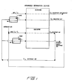
- Fig. 1 The overall process concept of the present invention is described in Fig. 1.
- ambient air at a temperature T i is supplied to the ASD where the oxygen contained therein will come into contact with and be adsorbed by a suitable adsorbent.
- the air exhaust, now being 0 2 depleted, is expelled from the ASD as waste.
- a second stream of air which may contain some recycled air from later stages, is then supplied to the ASD for delivery to the oxygen loaded adsorbent.
- the second stream is at a temperature T 2 , which is greater than the temperature T 1 of the first stream and thereby effects desorption of the previously loaded 0 2 from the adsorbent.
- the exiting stream is thus oxygen enriched.
- the oxygen enriched stream leaving the ASD is then divided into two separate streams.
- the first stream is cooled and then delivered to the ASD where the oxygen contained therein is loaded onto the adsorbent.
- the other oxygen-enriched stream is heated and then delivered to the ASD whefe oxygen loaded onto the adsorbent by the other oxygen enriched stream will be stripped so as to produce a doubly enriched stream of air.
- the ASD 10 comprises a plurality of fixed feed ports 12, to each of which may be supplied various feed materials.
- those materials include ambient air as well as recycled streams of oxygen enriched and oxygen depleted air.
- each fixed feed port 12 Moving about a circular path in periodic fluid communication with each of the above-described fixed feed ports 12 are a plurality of chambers 14 filled with an adsorbent which is capable of adsorbing oxygen, or any other component for which enrichment is desired.
- the rotating chambers 14 are connected to the fixed feed ports 12 via the conduits 13, which themselves rotate along with the chambers.
- the rotating chambers 14 are connected to the fixed discharge ports 16 via the conduits 15, which themselves rotate.
- each fixed feed port 12 will have a corresponding fixed discharge port 16.
- the feed materials are supplied continuously to their respective feed ports for periodic interaction with the adsorbent in each of the chambers 14. As material is discharged from the rotating chambers 14 through one of the fixed discharge ports 16, it may be purged from the system, recirculated back to a selected feed port, or a combination of both.
- the size and number of chambers 14 is strictly a matter of design choice dependent upon the degree of enrichment sought, the type of adsorbent used, and the volume of enriched air required. At a minimum, there should be at least about 25-30% more rotating chambers than fixed beds to avoid dead spots. Thus, it is within the ambit of this invention to provide 10-15 fixed feed ports and up to 60 rotating chambers. The system is effectively operated in a thermal swing mode at pressures between about 1 and about 4 atmospheres.
- adsorbent used is entirely dependent on the gaseous component enriched.
- adsorbents such as activated carbon molecular sieves and hexacyano molecular sieves such as those developed by Union Carbide and described in U.S. Patent No. 4,477,418 may be used.
- an adsorbent such as activated carbon would be suitable.
- the adsorbent may be used in conjunction with the presently claimed process.
- the tempera-0 380C ture of the feed being adsorbed can range 0-38°C from about 32°F to about 100°F), the upper limit being the more critical since higher temperatures disfavor gaseous adsorption.
- the materials fed to 66 to 149°C the desorption stage can typically ranger from 150°F to 300°F), the temperature being dependent primarily on the nature of the adsorbent.
- one or more additional feed ports may be provided in order to supply a stream of cooling air to the adsorbent after the desorption stage.
- This additional stream would act to decrease the temperature of the adsorbent from the at least 66°C(150°F) employed during desorption to the maximum of about 38°C (100°F)employed for adsorption.
- the additional cooling feed ports are not provided, the adsorbent will typically be cooled by an excess of air fed through the adsorption stage feed ports.
- the rotational speed of the adsorbent-filled chambers is highly dependent on the construction of the ASD used i.e., the diameter of the chambers; the properties of the adsorbent i.e., its loading capacity; the depth of the adsorbent in the chambers and the material flow rates.
- the present process enables air to be enriched to contain in excess of 30% by volume of oxygen in contrast to the 21% normally found.
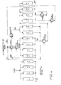
- FIG. 3 the process for enriching the oxygen content of air is illustrated.
- the particular embodiment illustrated utilizes fourteen fixed feed and discharge ports as well as twenty rotating chambers.
- the fixed feed ports 1F-14F as well as the fixed discharge ports 1D-14D are depicted in Fig. 3.
- the general process is illustrated schematically in Fig. 4.
- Figure 4 should be viewed as illustrating the fixed feed and discharge ports.
- the rotating adsorbent-filled chambers can be viewed as a continuous or "infinite" bed.
- ambient air (I) is supplied to fixed feed ports 1F to 4F for delivery to the adsorbent-filled chambers where oxygen is loaded onto the adsorbent and the stream of air (II), which is now oxygen depleted, is expelled out of the system through fixed discharge ports 1 D to 4D.
- the temperature of the entering air (I) is no greater than 38oC abouti(100 * F)to insure adequate adsorption of the oxygen onto the adsorbent.
- the stream (VII) is fed into the ASD in order to strip the adsorbent of the 0 2 loaded while the chambers were being fed by cool air through ports 1F to 4F, the stream must be at a temperature greater than that of the ambient air feed stream 66 to 149°C (I). Generally, temperatures ranging from 66 to 149°C(150 to 300°F) are found satisfactory. The upper limit is dependent on the nature of the adsorbent.
- the stream (VII) fed into ports 5F-8F thus strips the oxygen from the adsorbent and is discharged from the ASD as two separate oxygen-enriched streams namely, stream (VIII) which originates from ports 5D and 6D and stream (IX), which originates from ports 7D and 8D.
- Stream (VIII) containing oxygen-enriched air is then cooled and supplied to fixed ports 9F and 10F where it is then delivered to chambers 14 where the higher levels of 0 2 contained therein are loaded onto the adsorbent. As depicted in F ig. 4, stream (VIII) is cooled by heat exchange with stream (VII).
- Stream (IX) which also contains oxygen-enriched air is heated and supplied to fixed ports 11F and 12F where it is delivered to the chambers containing adsorbent loaded with the 0 2 by oxygen-enriched stream (VIII). In this manner, the oxygen present in the first oxygen-enriched stream (VIII) is transferred to the second oxygen-enriched stream (IX) to produce double enriched streams of air (X) and (XI).
- a triple-enriched stream of air is obtained. More specifically, the double enriched stream (XI) is cooled and delivered to fixed port 13F for loading of the oxygen contained therein onto the adsorbent. The stream (X) of double enriched air is then heated and delivered to feed port 14F where it desorbs the oxygen deposited onto the adsorbent by stream (XI) to produce a triple-enriched stream of air.
- the oxygen depleted stream (IV) being discharged from port 13D is then recycled, as previously indicated, and combined with streams (III) and (V) for delivery to fixed ports 5F to 8F.
- the present process enables air to be enriched to contain in excess of 30% by volume of oxygen in contrast to the 21% normally found.
- Example shown is based on a so-called “single-pass" system to produce 0.462 m 3 /s, at standard temperature and pressure (60,000 SCFH)of 30% by volume oxygen enriched air.
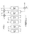
- a single pass oxygen enrichment system is shown in Fig. 5.
- the single pass concept illustrates the technique of continuous 0 2 adsorption/desorption using the ASD system. Any number of stages with intrastage heating and cooling can be utilized depending on the gases being processed, the adsorbent used and the degree of recovery or enrichment desired for the end use.
- ambient air is introduced in a two- stage counter-current fashion into the adsorption zone of the 0.462 m 3 s ASD.
- L 60,000 standard cubic feet per hour
- 30% oxygen enriched air is the desired end product.
- the ASD consists of multiple feed ports and uses 20 chambers one foot in diameter by three feet in height, containing a depth of two feet of molecular sieve type carbon.
- the rotational speed of the ASD is between 20 and 30 minutes per revolution.
- the entire system is operated at a pressure of 2 atmospheres (202.65 kPa).
- the ambient air (stream I') passes through the adsorption zone wherein a portion of the contained oxygen is adsorbed onto the carbon.
- Depleted air (II I ) exits the ASD and is discharged.
- Ambient air (III') is passed in a 0.154 to 0.193 m 3 /s counter-current fashion through the cooling zone. Approximately 0.154 to 0.193 m 3 /s(20,000 to 25,000 standard cubic feet per hour)are utilized in this step.
- This air is combined with preheated ambient air originating in stream (VII') and the mixture passes through heat exchanger Hl where the temperature is elevated to 93°C (200°F) or greater. The heated air leaves the exchanger and passes into the desorption zone where it removes residual oxygen from the sieving carbon.
- the discharged partially enriched air from this zone passes through a second heat exchanger H2 where the temperature of the gas is increased to 149°C (300°F) or greater depending on the limitation of the carbon or adsorbent. Heating of the air is accomplished in counter-current heat exchangers and hot combustion gas originating from any standard source (V') is used as the heating medium. Other techniques such as thermal fluid heat transfer, waste heat recovery and the like can be used to achieve this heating stage.
- the hot gas from the second heat exchanger H2 passes through the activated carbon to produce an enriched air at 149°C approximately (300°F) or above, again depending on the adsorbent, 0. 4 62 m3/s and at a rate of about/(60,000 standard cubic feet per hour).
- This enriched air is passed through a third heat exchanger H3 (preheater) in order to reclaim a portion of the heat and minimize thermal energy costs associated with the process.
- the final enriched air (VI') contains approximately 30% oxygen and is sent on to further procesing or to the end use.
- the enriched air contained in stream 6 can be sent to additional adsorption zones as indicated in Fig. 4. In this manner a bootstrap technique is utilized to build up the final concentration of oxygen.
Abstract
Description
- The present invention relates to a process for enhancing the concentration of one component contained in a multi-component gas and, more particularly, to a process for enriching air by increasing the concentration of oxygen therein.
- Oxygen-enriched air, as opposed to pure oxygen, is often sought by industry in order to improve combustion or, more recently, to enhance processes in biotechnology. Heretofore, oxygen-enriched air has been obtained by either mixing air with pure oxygen produced by well known cryogenic techniques or, alternatively, by pressure-swing adsorption techniques.
- In conventional pressure-swing techniques, air under pressure is passed through a fixed bed adsorption system. Typically, an adsorbent such as a molecular sieve is used, the sieve preferentially adsorbing nitrogen. The gas discharged from the bed is thus higher in oxygen content than that being fed into the bed. After the adsorption, the pressure is reduced to atmospheric or even sub-atmospheric levels, and the nitrogen is desorbed from the bed. The bed is then returned to the nitrogen adsorption cycle.
- The above-described technique is suitable for producing relatively small quantities of enriched air so long as the system remains relatively simple. However, as the system becomes more complex or if a higher degree of enrichment is required, the pressure-swing techniques as well as any other techniques utilizing fixed bed systems become unduly complicated and expensive to run.
- Other available air enrichment systems, such as membrane separation systems, often do not require as complicated a set-up but are nonetheless disadvantageous due to the limited amounts of air which may be treated therewith.
- In view of the foregoing limitations and shortcomings of prior art processes, as well as other disadvantages not specifically mentioned above, it should be apparent that there still exists a need in the art for a process wherein large volumes of air may be continuously and economically enriched with respect to oxygen content. It is, therefore, a primary objective of this invention to fulfill that need by providing a process for enriching air utilizing an Advanced Separation Device (ASD) which makes the enrichment of air by adsorption techniques economically practicable.
- Another object of this invention is to provide a process for enriching air which makes it possible to divide a stream of oxygen-enriched air into two separate streams and to then strip the oxygen from the first stream for simultaneous and continuous loading into the second stream so as to obtain a product air stream having an even greater concentration of oxygen.
- Yet another object of this invention to provide a process for enriching air which may be carried out with virtually any volume of air at relatively low pressures i.e., below four atmospheres thus making it satisfactory regardless of the process requirements.
- A further object of this invention is to provide a process which utilizes a thermal swing approach to regenerate the adsorbent bed which improves the versatility of this technique.
- Briefly described, those and other objects of the inven- ti are accomplished by carrying out the process in an Advanced Separation Device (ASD) which comprises a plurality of adsorbent filled chambers which move about a circular path in periodic fluid communication with a plurality of fixed feed ports and fixed discharge ports at an end of the chambers opposite to that of the fixed feed ports. Since materials being discharged from the fixed discharge ports are readily purged from the system, recirculated to another feed port, or a combination of both, it is possible by virtue of the ASD to:
- 1) load the oxygen contained in air onto a suitable adsorbent in the chambers by supplying air at relatively low pressure to one or more fixed adsorption stage feed ports for delivery into the chamber;
- 2) strip the oxygen from the adsorbent by supplying a higher temperature stream containing air to one or more fixed desorption stage feed ports for delivery into the chambers containing the oxygen loaded adsorbent so as to produce an oxygen enriched stream of air; and
- 3) divide the oxygen-enriched stream of air into two separate streams, the first of which is cooled and supplied to a second adsorption stage feed port where it is delivered and loaded onto the adsorbent and the second of which is heated and supplied to a second desorption stage feed port where it strips the adsorbent loaded with oxygen by the first oxygen-enriched stream thereby resulting in a further enriched product stream. This process of dividing the oxygen enriched stream into two separate streams and then stripping the oxygen from one of those streams to simultaneously and continuously further enrich the other stream may be repeated one or more times as desired.
- Some embodiments of the invention will now be described, by way of example, with reference to the accompanying drawings in which:-
- Figure 1 is a flow diagram illustrating the overall process concept of the invention;
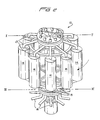
- Figure 2 is a perspective view of the Advanced Separation Device;
- Figure 3 is a cross-sectional view taken along lines I-I and II-II of Figure 2 which shows the fixed feed ports and fixed discharge ports respectively;
- Figure 4 is a schematic illustration of the process being carried out in the Advanced Separation Device; and
- Figure 5 is a schematic view of a single pass oxygen enrichment process carried out in the Advanced Separation Device.
- The process of the present invention is carried out in the Advanced Separation Device which is described in detail in assignee's copending application S.N. 713,492 filed March 19, 1985, the disclosure of which is hereby incorporated by reference.
- The overall process concept of the present invention is described in Fig. 1. Generally, ambient air at a temperature Ti is supplied to the ASD where the oxygen contained therein will come into contact with and be adsorbed by a suitable adsorbent. The air exhaust, now being 02 depleted, is expelled from the ASD as waste.
- A second stream of air, which may contain some recycled air from later stages, is then supplied to the ASD for delivery to the oxygen loaded adsorbent. The second stream is at a temperature T2, which is greater than the temperature T1 of the first stream and thereby effects desorption of the previously loaded 02 from the adsorbent. The exiting stream is thus oxygen enriched.
- The oxygen enriched stream leaving the ASD is then divided into two separate streams. The first stream is cooled and then delivered to the ASD where the oxygen contained therein is loaded onto the adsorbent. The other oxygen-enriched stream is heated and then delivered to the ASD whefe oxygen loaded onto the adsorbent by the other oxygen enriched stream will be stripped so as to produce a doubly enriched stream of air.
- Although the overall process concept described above as well as the specific embodiments described below all relate to the enrichment of the oxygen content in air, it will be appreciated that the process concept is equally applicable to other multi-component gases when it is desired to increase the concentration of one particular component. All that is required is that the adsorbent material used have a greater affinity for the one component sought to be enriched than for the other components of the gaseous mixture.
- For convenience, a brief description of the ASD, illustrated at Figure 2, will be provided.
- The ASD 10 comprises a plurality of
fixed feed ports 12, to each of which may be supplied various feed materials. In the case of the present invention, those materials include ambient air as well as recycled streams of oxygen enriched and oxygen depleted air. - Moving about a circular path in periodic fluid communication with each of the above-described
fixed feed ports 12 are a plurality ofchambers 14 filled with an adsorbent which is capable of adsorbing oxygen, or any other component for which enrichment is desired. In the particular embodiment illustrated, therotating chambers 14 are connected to thefixed feed ports 12 via theconduits 13, which themselves rotate along with the chambers. In similar fashion, a plurality of fixed discharge ports 16-are provided at an end of the chambers opposite to that of thefixed feed ports 12. Therotating chambers 14 are connected to thefixed discharge ports 16 via theconduits 15, which themselves rotate. Generally, eachfixed feed port 12 will have a correspondingfixed discharge port 16. - The feed materials are supplied continuously to their respective feed ports for periodic interaction with the adsorbent in each of the
chambers 14. As material is discharged from therotating chambers 14 through one of thefixed discharge ports 16, it may be purged from the system, recirculated back to a selected feed port, or a combination of both. - The size and number of
chambers 14 is strictly a matter of design choice dependent upon the degree of enrichment sought, the type of adsorbent used, and the volume of enriched air required. At a minimum, there should be at least about 25-30% more rotating chambers than fixed beds to avoid dead spots. Thus, it is within the ambit of this invention to provide 10-15 fixed feed ports and up to 60 rotating chambers. The system is effectively operated in a thermal swing mode at pressures between about 1 and about 4 atmospheres. - The type of adsorbent used is entirely dependent on the gaseous component enriched. When it is desired to enrich the oxygen content of air, adsorbents such as activated carbon molecular sieves and hexacyano molecular sieves such as those developed by Union Carbide and described in U.S. Patent No. 4,477,418 may be used. Where it is desired to enrich the organic solvent concentration in a mixture containing the solvent and air, an adsorbent such as activated carbon would be suitable. As long as the adsorbent has a higher affinity for the component being enriched and will release that component when desired, the adsorbent may be used in conjunction with the presently claimed process.
- There are not strict temperature requirements for carrying out the process so long as the feed materials used in the desorption stage are at a higher temperature than those used during the adsorption stage. Typically, therefore, the tempera-0 380C ture of the feed being adsorbed can range 0-38°C from about 32°F to about 100°F), the upper limit being the more critical since higher temperatures disfavor gaseous adsorption. The materials fed to 66 to 149°C the desorption stage can typically ranger from 150°F to 300°F), the temperature being dependent primarily on the nature of the adsorbent.
- Optionally, one or more additional feed ports may be provided in order to supply a stream of cooling air to the adsorbent after the desorption stage. This additional stream would act to decrease the temperature of the adsorbent from the at least 66°C(150°F) employed during desorption to the maximum of about 38°C (100°F)employed for adsorption. When the additional cooling feed ports are not provided, the adsorbent will typically be cooled by an excess of air fed through the adsorption stage feed ports.
- The rotational speed of the adsorbent-filled chambers is highly dependent on the construction of the ASD used i.e., the diameter of the chambers; the properties of the adsorbent i.e., its loading capacity; the depth of the adsorbent in the chambers and the material flow rates.
- The present process enables air to be enriched to contain in excess of 30% by volume of oxygen in contrast to the 21% normally found.
- The following Examples are presented solely for illustrative purposes and should in.no way be construed as limiting the process disclosed and claimed.
- Referring now to Figures 3 and 4, the process for enriching the oxygen content of air is illustrated. The particular embodiment illustrated utilizes fourteen fixed feed and discharge ports as well as twenty rotating chambers. The fixed feed ports 1F-14F as well as the fixed discharge ports 1D-14D are depicted in Fig. 3. The general process is illustrated schematically in Fig. 4. Figure 4 should be viewed as illustrating the fixed feed and discharge ports. The rotating adsorbent-filled chambers can be viewed as a continuous or "infinite" bed.
- When using molecular sieving as the adsorbent, it is possible to obtain 0.385m3/s (50,000 std ft3/hr)of air containing 30% by 305mm 0.085m3
volume 02 using twenty chambers(1 ft in) diameter with a volume of4 (3 ft3)filled with adsorbent to a depth of 610mm (2 ft). Of course, if greater volumes of enriched air are required, or if a further enriched air is needed, the size and number of adsorbent-filled chambers may be varied accordingly. The system is effectively operated in a thermal swing mode at a total system pressure of two atmospheres. - As illustrated in Figs. 3 and 4, ambient air (I) is supplied to fixed feed ports 1F to 4F for delivery to the adsorbent-filled chambers where oxygen is loaded onto the adsorbent and the stream of air (II), which is now oxygen depleted, is expelled out of the system through fixed discharge ports 1D to 4D. The temperature of the entering air (I) is no greater than 38oC abouti(100*F)to insure adequate adsorption of the oxygen onto the adsorbent.
- Into fixed
feed ports 5F to 8F are fed ambient air (III), recycled oxygen depleted stream (IV) originating from fixeddischarge port 13D and recycled oxygen depleted stream (V) originating from fixeddischarge ports 9D and 10D. The proportion by volume of streams (III), (IV) and (V) which are combined into a single stream (VII) for entry intoports 5F to 8F ranges from 5 to 10 parts (III), 0 to 10 parts (IV) and 0 to 10 parts (V). This is controlled using standard blowers, automatic valves and conventional flow ratio control systems. - Because the stream (VII) is fed into the ASD in order to strip the adsorbent of the 02 loaded while the chambers were being fed by cool air through ports 1F to 4F, the stream must be at a temperature greater than that of the ambient air feed stream 66 to 149°C (I). Generally, temperatures ranging from 66 to 149°C(150 to 300°F) are found satisfactory. The upper limit is dependent on the nature of the adsorbent.
- The stream (VII) fed into
ports 5F-8F thus strips the oxygen from the adsorbent and is discharged from the ASD as two separate oxygen-enriched streams namely, stream (VIII) which originates fromports ports - Stream (VIII) containing oxygen-enriched air is then cooled and supplied to fixed
ports 9F and 10F where it is then delivered tochambers 14 where the higher levels of 02 contained therein are loaded onto the adsorbent. As depicted in Fig. 4, stream (VIII) is cooled by heat exchange with stream (VII). - Stream (IX), which also contains oxygen-enriched air is heated and supplied to fixed
ports 11F and 12F where it is delivered to the chambers containing adsorbent loaded with the 02 by oxygen-enriched stream (VIII). In this manner, the oxygen present in the first oxygen-enriched stream (VIII) is transferred to the second oxygen-enriched stream (IX) to produce double enriched streams of air (X) and (XI). - By following a similar procedure, a triple-enriched stream of air is obtained. More specifically, the double enriched stream (XI) is cooled and delivered to fixed
port 13F for loading of the oxygen contained therein onto the adsorbent. The stream (X) of double enriched air is then heated and delivered to feedport 14F where it desorbs the oxygen deposited onto the adsorbent by stream (XI) to produce a triple-enriched stream of air. - The oxygen depleted stream (IV) being discharged from
port 13D is then recycled, as previously indicated, and combined with streams (III) and (V) for delivery to fixedports 5F to 8F. - By the above-described process, it is now possible to actually divide a stream of enriched air so as to use one stream to further enrich the other stream. Such may be done continuously and economically, i.e., without complicated valving arrangements, by virtue of the ASD.
- The present process enables air to be enriched to contain in excess of 30% by volume of oxygen in contrast to the 21% normally found.
- For simplicity, the Example shown is based on a so- called "single-pass" system to produce 0.462 m3/s, at standard temperature and pressure (60,000 SCFH)of 30% by volume oxygen enriched air.
- A single pass oxygen enrichment system is shown in Fig. 5. The single pass concept illustrates the technique of continuous 02 adsorption/desorption using the ASD system. Any number of stages with intrastage heating and cooling can be utilized depending on the gases being processed, the adsorbent used and the degree of recovery or enrichment desired for the end use.
- Referring to Fig. 5, ambient air is introduced in a two- stage counter-current fashion into the adsorption zone of the 0.462 m3 s ASD. For this systemL(60,000 standard cubic feet per hour)of 30% oxygen enriched air is the desired end product. The ASD consists of multiple feed ports and uses 20 chambers one foot in diameter by three feet in height, containing a depth of two feet of molecular sieve type carbon. The rotational speed of the ASD is between 20 and 30 minutes per revolution. The entire system is operated at a pressure of 2 atmospheres (202.65 kPa).
- The ambient air (stream I') passes through the adsorption zone wherein a portion of the contained oxygen is adsorbed onto the carbon. Depleted air (III) exits the ASD and is discharged.
- Moving now in the direction opposite of rotation for purposes of clarity, the bed after desorption is warm and some cooling is beneficial in order to maximize adsorption in the subsequent adsorption zone. Ambient air (III') is passed in a 0.154 to 0.193 m3/s counter-current fashion through the cooling zone. Approximately 0.154 to 0.193 m3/s(20,000 to 25,000 standard cubic feet per hour)are utilized in this step. This air is combined with preheated ambient air originating in stream (VII') and the mixture passes through heat exchanger Hl where the temperature is elevated to 93°C (200°F) or greater. The heated air leaves the exchanger and passes into the desorption zone where it removes residual oxygen from the sieving carbon. The discharged partially enriched air from this zone passes through a second heat exchanger H2 where the temperature of the gas is increased to 149°C (300°F) or greater depending on the limitation of the carbon or adsorbent. Heating of the air is accomplished in counter-current heat exchangers and hot combustion gas originating from any standard source (V') is used as the heating medium. Other techniques such as thermal fluid heat transfer, waste heat recovery and the like can be used to achieve this heating stage.
- The hot gas from the second heat exchanger H2 passes through the activated carbon to produce an enriched air at 149°C approximately (300°F) or above, again depending on the adsorbent, 0.462 m3/s and at a rate of about/(60,000 standard cubic feet per hour). This enriched air is passed through a third heat exchanger H3 (preheater) in order to reclaim a portion of the heat and minimize thermal energy costs associated with the process. The final enriched air (VI') contains approximately 30% oxygen and is sent on to further procesing or to the end use.
- Approximately 416 g/s (55 pounds per minute)of sieving carbon is moving between zones as a result of the ASD approach. The total carbon charge is on the order of 499 kg (1,100 pounds. Thus it is apparent that fairly significant quantities of enriched air are produced with a minimal amount of carbon charge.
- If desired the enriched air contained in
stream 6 can be sent to additional adsorption zones as indicated in Fig. 4. In this manner a bootstrap technique is utilized to build up the final concentration of oxygen.
Claims (7)
Applications Claiming Priority (2)
| Application Number | Priority Date | Filing Date | Title |
|---|---|---|---|
| US747434 | 1985-06-21 | ||
| US06/747,434 US4612022A (en) | 1985-06-21 | 1985-06-21 | Process for increasing the concentration of one component in a multi-component _gaseous mixture |
Publications (2)
| Publication Number | Publication Date |
|---|---|
| EP0205709A2 true EP0205709A2 (en) | 1986-12-30 |
| EP0205709A3 EP0205709A3 (en) | 1988-05-25 |
Family
ID=25005044
Family Applications (1)
| Application Number | Title | Priority Date | Filing Date |
|---|---|---|---|
| EP85308711A Withdrawn EP0205709A3 (en) | 1985-06-21 | 1985-11-29 | Process for enriching a component gas |
Country Status (10)
| Country | Link |
|---|---|
| US (1) | US4612022A (en) |
| EP (1) | EP0205709A3 (en) |
| JP (1) | JPS6291224A (en) |
| KR (1) | KR870000093A (en) |
| CN (1) | CN1005253B (en) |
| AU (1) | AU570904B2 (en) |
| CA (1) | CA1290706C (en) |
| ES (1) | ES8702158A1 (en) |
| IL (1) | IL77060A0 (en) |
| IN (1) | IN164708B (en) |
Cited By (2)
| Publication number | Priority date | Publication date | Assignee | Title |
|---|---|---|---|---|
| EP0301090A1 (en) * | 1987-02-09 | 1989-02-01 | Rad Systems, Inc. | Regenerating dynamic adsorber system and method for contaminant removal |
| EP0368435A2 (en) * | 1988-11-02 | 1990-05-16 | Colortronic Co., Ltd. | Dehumidified air generator employing adsorbent |
Families Citing this family (27)
| Publication number | Priority date | Publication date | Assignee | Title |
|---|---|---|---|---|
| JPS6126647U (en) * | 1984-07-23 | 1986-02-17 | トヨタ自動車株式会社 | Indoor mirror mounting structure |
| US4778492A (en) * | 1987-02-19 | 1988-10-18 | Advanced Separation Technologies Incorporated | Continuous gas treatment method and apparatus for adsorption processes |
| AT389822B (en) * | 1988-07-08 | 1990-02-12 | Andritz Ag Maschf | METHOD FOR CONTINUOUSLY CLEANING GASES OF CARRYING LOADED MATERIALS AND DEVICE FOR ITS IMPLEMENTATION |
| US4999033A (en) * | 1989-05-31 | 1991-03-12 | Bry-Air, Inc. | Integrally valved, low friction indexing desiccant bed dehumidifier |
| US4948392A (en) * | 1989-07-25 | 1990-08-14 | Institute Of Gas Technology | Heat input for thermal regenerative desiccant systems |
| FR2667801B1 (en) * | 1990-10-11 | 1992-12-04 | Air Liquide | PROCESS AND EQUIPMENT FOR SEPARATION BY ADSORPTION OF AT LEAST ONE CONSTITUENT OF A GASEOUS MIXTURE. |
| LU88160A1 (en) * | 1992-08-18 | 1993-10-27 | Fernande Schartz | METHOD AND DEVICE FOR SEPARATING GAS BY SELECTIVE VARIABLE PRESSURE ADSORPTION |
| US5487775A (en) * | 1994-05-09 | 1996-01-30 | The Boc Group, Inc. | Continuous pressure difference driven adsorption process |
| FR2722426B1 (en) * | 1994-07-18 | 1996-08-23 | Air Liquide | PROCESS FOR THE SEPARATION OF NITROGEN FROM A GAS MIXTURE BY ADSORPTION |
| WO1996024554A1 (en) * | 1995-02-06 | 1996-08-15 | Nippon Sanso Corporation | Ozone enriching method |
| US5676826A (en) * | 1995-04-19 | 1997-10-14 | Advanced Separation Technologies Incorporated | Fluid-solid contacting apparatus |
| US5672197A (en) * | 1995-10-11 | 1997-09-30 | Rothchild; Ronald D. | Gas separation by continuous pressure-swing chromatography |
| US6398853B1 (en) | 1998-12-16 | 2002-06-04 | Quest Air Gases Inc. | Gas separation with split stream centrifugal turbomachinery |
| US6905535B2 (en) * | 1998-12-16 | 2005-06-14 | Questair Technologies Inc. | Gas separation with split stream centrifugal turbomachinery |
| CA2274388A1 (en) * | 1999-06-10 | 2000-12-10 | Bowie Keefer | Surge adsorber flow regulation for modular pressure swing adsorption |
| CA2274390A1 (en) * | 1999-06-10 | 2000-12-10 | Questor Industries Inc. | Multistage chemical separation method and apparatus using pressure swing adsorption |
| US6431202B1 (en) | 1999-12-01 | 2002-08-13 | Calgon Carbon Corporation | Fluid-directing multiport rotary valve |
| US6630012B2 (en) * | 2001-04-30 | 2003-10-07 | Battelle Memorial Institute | Method for thermal swing adsorption and thermally-enhanced pressure swing adsorption |
| US6517610B1 (en) * | 2001-11-13 | 2003-02-11 | The United States Of America As Represented By The Secretary Of The Navy | Microelectromechanical gas concentrator |
| US20040099605A1 (en) * | 2002-07-29 | 2004-05-27 | Chen-Chou Chiang | High performance continuous reaction/separation process using a continuous liquid-solid contactor |
| US7108789B2 (en) * | 2002-07-29 | 2006-09-19 | Calgon Carbon Corporation | High performance continuous reaction/separation process using a continuous liquid-solid contactor |
| FR2895272B1 (en) * | 2005-12-22 | 2008-06-06 | Inst Francais Du Petrole | PROCESS AND DEVICE FOR CONTINUOUS PRODUCTION OF OXYGEN-RICH GAS FROM OXYGEN-CONTAINING GAS |
| US10744448B2 (en) * | 2015-07-02 | 2020-08-18 | Solvay Sa | Gas separation unit comprising a rotor with a plurality of sectors and a stator |
| CA2991624A1 (en) * | 2015-07-13 | 2017-01-19 | Nuvera Fuel Cells, LLC | Pressure swing adsorbers with flow regulation by orifices |
| EP3345672A1 (en) * | 2017-01-05 | 2018-07-11 | Solvay SA | Gas separation unit comprising a rotor with a plurality of sectors and a stator |
| JP7158078B2 (en) * | 2018-07-09 | 2022-10-21 | 上海深城環保設備工程有限公司 | Gas adsorption separation device and its application |
| CN109529527A (en) * | 2018-11-06 | 2019-03-29 | 威海威高海盛医用设备有限公司 | A kind of nonisothermal pellet bed model for air adsorption separation |
Citations (3)
| Publication number | Priority date | Publication date | Assignee | Title |
|---|---|---|---|---|
| US3487608A (en) * | 1966-03-11 | 1970-01-06 | Roderich W Graff | Method and apparatus for adsorption of molecules from fluids |
| US3757492A (en) * | 1970-05-23 | 1973-09-11 | R Graff | Adsorber method and apparatus |
| US4522726A (en) * | 1984-07-30 | 1985-06-11 | Progress Equities Incorporated | Advanced separation device and method |
Family Cites Families (16)
| Publication number | Priority date | Publication date | Assignee | Title |
|---|---|---|---|---|
| US2630191A (en) * | 1946-10-28 | 1953-03-03 | Jefferson Lake Sulphur Co | Cyclic adsorption process |
| US2771964A (en) * | 1953-04-13 | 1956-11-27 | Jefferson Lake Sulphur Co | Method of recovering h2s from natural gas |
| US2739670A (en) * | 1954-01-26 | 1956-03-27 | Jefferson Lake Sulphur Co | Cyclic adsorption process |
| US2784804A (en) * | 1955-05-06 | 1957-03-12 | Jefferson Lake Sulphur Co | Cyclic adsorption process for removing h2s from natural gas |
| US2799360A (en) * | 1956-01-16 | 1957-07-16 | Jefferson Lake Sulphur Co | Cyclic adsorption process for the recovery of ethane from a gaseous mixture consisting of methane and ethane |
| US2799361A (en) * | 1956-10-05 | 1957-07-16 | Jefferson Lake Sulphur Co | Cyclic adsorption process for removal and/or recovery of h2s from natural gas |
| US2799362A (en) * | 1956-10-19 | 1957-07-16 | Jefferson Lake Sulphur Co | Cyclic adsorption process |
| US2799363A (en) * | 1956-11-05 | 1957-07-16 | Jefferson Lake Sulphur Co | Cyclic adsorption process |
| US2799364A (en) * | 1956-11-23 | 1957-07-16 | Jefferson Lake Sulphur Co | Cyclic adsorption process |
| US2823764A (en) * | 1957-02-08 | 1958-02-18 | Jefferson Lake Sulphur Co | Cyclic adsorption processes for removal and/or recovery of condensable hydrocarbons from natural gas |
| US2861651A (en) * | 1957-10-07 | 1958-11-25 | Jefferson Lake Sulphur Co | Cyclic adsorption processes for recovery of h2s from natural gas employing two activation cycles |
| US2877861A (en) * | 1957-12-23 | 1959-03-17 | Jefferson Lake Sulphur Co | Method of and system for recovering hs from natural gas containing a high percentage of hs |
| DE1181674B (en) * | 1959-01-05 | 1964-11-19 | Dr Josef Heyes | Device for the separation of gas or liquid mixtures |
| US3080692A (en) * | 1960-07-11 | 1963-03-12 | Nat Tank Co | Adsorption process and apparatus for gas dehydration and hydrocarbon recovery |
| DE2652486A1 (en) * | 1976-11-18 | 1978-05-24 | Bergwerksverband Gmbh | METHOD FOR THE EXTRACTION OF NITROGEN-GASES FROM GASES CONTAINING N LOW 2 LESS THAN AT LEAST O LOW 2, E.g. AIR |
| US4477418A (en) * | 1983-08-23 | 1984-10-16 | Union Carbide Corporation | Process for adsorption |
-
1985
- 1985-06-21 US US06/747,434 patent/US4612022A/en not_active Expired - Lifetime
- 1985-11-14 IL IL77060A patent/IL77060A0/en unknown
- 1985-11-15 CA CA000495480A patent/CA1290706C/en not_active Expired - Fee Related
- 1985-11-20 IN IN976/DEL/85A patent/IN164708B/en unknown
- 1985-11-21 ES ES549132A patent/ES8702158A1/en not_active Expired
- 1985-11-27 KR KR1019850008856A patent/KR870000093A/en not_active Application Discontinuation
- 1985-11-28 CN CN85108746.9A patent/CN1005253B/en not_active Expired
- 1985-11-29 EP EP85308711A patent/EP0205709A3/en not_active Withdrawn
- 1985-11-29 JP JP60267573A patent/JPS6291224A/en active Granted
- 1985-12-02 AU AU50549/85A patent/AU570904B2/en not_active Ceased
Patent Citations (3)
| Publication number | Priority date | Publication date | Assignee | Title |
|---|---|---|---|---|
| US3487608A (en) * | 1966-03-11 | 1970-01-06 | Roderich W Graff | Method and apparatus for adsorption of molecules from fluids |
| US3757492A (en) * | 1970-05-23 | 1973-09-11 | R Graff | Adsorber method and apparatus |
| US4522726A (en) * | 1984-07-30 | 1985-06-11 | Progress Equities Incorporated | Advanced separation device and method |
Cited By (4)
| Publication number | Priority date | Publication date | Assignee | Title |
|---|---|---|---|---|
| EP0301090A1 (en) * | 1987-02-09 | 1989-02-01 | Rad Systems, Inc. | Regenerating dynamic adsorber system and method for contaminant removal |
| EP0301090A4 (en) * | 1987-02-09 | 1990-01-23 | Rad Systems Inc | Regenerating dynamic adsorber system and method for contaminant removal. |
| EP0368435A2 (en) * | 1988-11-02 | 1990-05-16 | Colortronic Co., Ltd. | Dehumidified air generator employing adsorbent |
| EP0368435A3 (en) * | 1988-11-02 | 1991-02-27 | Colortronic Co., Ltd. | Dehumidified air generator employing adsorbent |
Also Published As
| Publication number | Publication date |
|---|---|
| CN85108746A (en) | 1987-02-04 |
| CA1290706C (en) | 1991-10-15 |
| KR870000093A (en) | 1987-02-16 |
| IN164708B (en) | 1989-05-13 |
| AU570904B2 (en) | 1988-03-24 |
| JPH0244571B2 (en) | 1990-10-04 |
| AU5054985A (en) | 1986-12-24 |
| ES8702158A1 (en) | 1986-12-16 |
| CN1005253B (en) | 1989-09-27 |
| US4612022A (en) | 1986-09-16 |
| JPS6291224A (en) | 1987-04-25 |
| EP0205709A3 (en) | 1988-05-25 |
| ES549132A0 (en) | 1986-12-16 |
| IL77060A0 (en) | 1986-04-29 |
Similar Documents
| Publication | Publication Date | Title |
|---|---|---|
| EP0205709A2 (en) | Process for enriching a component gas | |
| EP0769319B1 (en) | Duplex adsorption process | |
| US4614525A (en) | Pressure swing process for the adsorptive separation of gaseous mixtures | |
| US4406675A (en) | RPSA Process | |
| EP0248510B1 (en) | Auxiliary bed pressure swing adsorption moleculair sieve | |
| US4566881A (en) | Process and apparatus for producing oxygen with a low proportion of argon from air | |
| US6878186B2 (en) | Pure vacuum swing adsorption system and apparatus | |
| AU753144B2 (en) | High temperature adsorption process | |
| US5944874A (en) | Solid electrolyte ionic conductor systems for the production of high purity nitrogen | |
| JPS62502682A (en) | Ozone production method and equipment | |
| US6527831B2 (en) | Argon purification process | |
| KR20000029194A (en) | Pressure swing adsorption method for production of an oxygen-enriched gas | |
| EP0114911A1 (en) | Novel repressurization for pressure swing adsorption system | |
| KR100326500B1 (en) | Vacuum/pressure swing adsorption(vpsa) method for production of an oxygan enriched gas | |
| JPS61222905A (en) | Manufacture of oxygen-rich air | |
| US2968160A (en) | Method and apparatus for separating gaseous mixtures including high boiling point impurities | |
| JPS6272504A (en) | Production of nitrogen having high purity | |
| US3498025A (en) | Adsorption process and apparatus | |
| GB2281229A (en) | An adsorber vessel | |
| US3355859A (en) | Selective adsorption of gases at low temperature | |
| EP0354259A1 (en) | Improved pressure swing adsorption process | |
| Sircar | Air fractionation by adsorption | |
| JPH0952703A (en) | Method for adsorbing nitrogen from gas mixture by using pressure pendulum adsorption with zeolite | |
| EP0114912B1 (en) | Novel repressurization for pressure swing adsorption system | |
| CN111450667B (en) | Separation method and apparatus for light inert gas |
Legal Events
| Date | Code | Title | Description |
|---|---|---|---|
| PUAI | Public reference made under article 153(3) epc to a published international application that has entered the european phase |
Free format text: ORIGINAL CODE: 0009012 |
|
| AK | Designated contracting states |
Kind code of ref document: A2 Designated state(s): AT CH DE FR GB IT LI NL SE |
|
| RAP1 | Party data changed (applicant data changed or rights of an application transferred) |
Owner name: ADVANCED SEPARATION TECHNOLOGIES INCORPORATED |
|
| PUAL | Search report despatched |
Free format text: ORIGINAL CODE: 0009013 |
|
| AK | Designated contracting states |
Kind code of ref document: A3 Designated state(s): AT CH DE FR GB IT LI NL SE |
|
| 17P | Request for examination filed |
Effective date: 19881119 |
|
| 17Q | First examination report despatched |
Effective date: 19890322 |
|
| STAA | Information on the status of an ep patent application or granted ep patent |
Free format text: STATUS: THE APPLICATION IS DEEMED TO BE WITHDRAWN |
|
| 18D | Application deemed to be withdrawn |
Effective date: 19900623 |
|
| RIN1 | Information on inventor provided before grant (corrected) |
Inventor name: BERRY, W. WES |