EP0205129A2 - Pneumatic pressure switch for controlling the air pressure-chamber of fluid-floaded armatures - Google Patents
Pneumatic pressure switch for controlling the air pressure-chamber of fluid-floaded armatures Download PDFInfo
- Publication number
- EP0205129A2 EP0205129A2 EP86107773A EP86107773A EP0205129A2 EP 0205129 A2 EP0205129 A2 EP 0205129A2 EP 86107773 A EP86107773 A EP 86107773A EP 86107773 A EP86107773 A EP 86107773A EP 0205129 A2 EP0205129 A2 EP 0205129A2
- Authority
- EP
- European Patent Office
- Prior art keywords
- valve
- compressed air
- pressure switch
- pneumatic pressure
- air chamber
- Prior art date
- Legal status (The legal status is an assumption and is not a legal conclusion. Google has not performed a legal analysis and makes no representation as to the accuracy of the status listed.)
- Granted
Links
Images


Classifications
-
- G—PHYSICS
- G05—CONTROLLING; REGULATING
- G05D—SYSTEMS FOR CONTROLLING OR REGULATING NON-ELECTRIC VARIABLES
- G05D16/00—Control of fluid pressure
- G05D16/04—Control of fluid pressure without auxiliary power
- G05D16/06—Control of fluid pressure without auxiliary power the sensing element being a flexible membrane, yielding to pressure, e.g. diaphragm, bellows, capsule
- G05D16/0611—Control of fluid pressure without auxiliary power the sensing element being a flexible membrane, yielding to pressure, e.g. diaphragm, bellows, capsule the sensing element being deformable, e.g. Bourdon tube
Definitions
- the invention relates to a pneumatic pressure switch for controlling the compressed air chamber of fittings through which medium flows, in particular safety valves loaded with additional loads, the compressed air chamber being connected via an air supply line to the compressed air source and via an air discharge line to an outlet valve which has a larger opening cross section than the possibly throttled air supply line and is controlled by the pneumatic pressure switch, which has an expansion element connected to the medium pressure line, one end of which is firmly seated on the medium connection and the free other end, which is closed in a pressure-tight manner, moves more or less by elastic deformation depending on the medium pressure.
- pneumatic pressure switches are known in which the movable free end of the expansion element designed as a spiral Bourdon tube carries a control flag which interrupts an air jet directed from a jet nozzle onto a collecting nozzle when the response pressure is reached. This interruption of the air jet relieves an outlet valve in the membrane chamber which is connected to the catching nozzle and is designed as a diaphragm valve, as a result of which a valve body loaded by a counter spring opens the compressed air chamber of the additional loading cylinder to the atmosphere.
- control flag when using the control flag as a pressure switch, additional measures must be taken in special cases, such as installing supply or exhaust air throttles or interposing air reservoirs, in order to adapt the dynamic behavior of the safety valve to the requirements of the system.
- the object of the invention is to improve the pneumatic pressure switch for controlling the compressed air chamber of fittings through which the medium flows so that, with the lowest air consumption and high switching reliability, a quick response of the fitting to pressure changes is ensured without overreactions.
- the movable end of the expansion member is designed as a closure member of the exhaust valve
- the valve seat can be made so large in diameter that the seat circumference even with a very small valve lift, which is only about 1/5 to 1 / 10 of the control flag path is sufficient to release a sufficiently large outlet cross-section.
- the expansion member can thus be made much stiffer and less susceptible to vibrations and pulsations. Since the outlet valve is closed in the normal state, hardly any air consumption occurs at the pressure switch.
- valve seat of the exhaust valve which is flexibly connected to the air discharge line to the compressed air chamber, is in this case provided on a support which is elastically suspended by means of adjusting springs and which is connected by a first control air chamber in the closing direction and by a second Control air chamber can be shifted in the opposite direction, so that the opening stroke of the exhaust valve per pressure increase unit increases or decreases in contrast to a rigid valve seat.
- the stroke of the outlet valve is dependent not only on the medium pressure, but also on the pressure in the air discharge line.
- the stroke of the exhaust valve determines the pressure in the air discharge line, feedback is achieved which, depending on the direction of action, acts as positive or negative feedback. With this feedback, the dynamic switching behavior of the valve can be changed significantly. If, for example, the reaction of the closure body of a safety valve to changes in medium pressure is too slow, the desired response behavior of the valve can be achieved by a correspondingly softer adjustment spring and also by switching the connections of the control air chamber from negative feedback to positive feedback. If the valve responds too quickly, the reverse procedure can also be used to achieve a fine adjustment to the desired valve reaction.
- the opening cross section of the outlet valve is not large enough to discharge the air from the compressed air chamber and the air flowing in continuously from the compressed air source quickly enough.
- the exhaust valve is a pilot valve for a diaphragm or piston valve designed as a servo valve that can be made large enough in cross-section so that the amount of air can escape quickly enough and is supplied quickly enough.
- a safety valve 1 shows a safety valve 1, the inlet of which is connected to the medium pressure line 2 and which carries an additional load cylinder 3 with a compressed air chamber 4.
- the compressed air is introduced from the compressed air source 5 into the compressed air chamber 4 of the safety valve 1 via the air supply line 7 provided with a throttle 6. To relieve the pressure air chamber 4, it is connected to the outlet valve 9 via the air discharge line 8.
- the outlet valve 9 is part of a pneumatic pressure switch, the expansion member 10 is held at its fixed end 11 in the bearing block 12 of the pressure switch and is in open connection via the medium connection 13 and the connecting line 14 with the medium pressure line 2.
- the free end 15 of the expansion member 10, which moves under the action of the medium pressure, is designed as a closure member of the outlet valve 9.
- the valve seat 16 of the exhaust valve 9 is formed by the edge of a bore 18 made in a carrier 17, to which the air discharge line 8 is flexibly connected.
- the carrier 17 is supported at its one end in the joint 19 of the post 20 and rests at its other end between two of the support '20 held Anpledgefedern 21.
- the carrier is resiliently mounted movable with its valve seat 16 17th
- the carrier 17 is provided with two symmetrical support knobs 22 which abut the membranes 23 of the control air chambers 24 and 25.
- the control air chamber 24 is openly connected to the air discharge line 8 via the connecting line 26, while the control air chamber 25 is connected to the compressed air source 5 via the connecting line 27. If positive feedback is to be provided instead of the negative feedback shown, the connecting lines 26 and 27 for the control air chambers 24 and 25 are to be interchanged by the cross circuit 28 shown in broken lines.
- the support 20 is rotatably attached to the bearing block 12 at one end via the joint 29.
- a support spring 30 and a set screw 31 are provided at the other movable end of the support 20.
- the set screw 31 has two threaded sections 32 and 33 with the same direction, slightly different pitches.
- the threaded section 32 is screwed directly into the bearing block 12, while the upper threaded section 33 is screwed into the joint nut 34.
- a valve ball 35 compensating for the non-parallelism is provided, for holding the guide cage 36 on the carrier 17.
- the opening and closing process of the safety valve 1 can be influenced by the control air chambers 24 and 25. If the control air chambers 24 and 25 are connected as shown, when the outlet valve 9 is opened, the force of the control air chamber 25 acting in the closing direction is greater than the opposite force of the control air chamber 24, as a result of which the carrier 17 moves with the valve seat 16 in the valve closing direction .
- the size of this movement depends from the geometric dimensions of the control device and can be easily increased or decreased by exchanging the adjustment springs 21. This countercoupling slows down the venting of the compressed air chamber 4 to a greater or lesser extent, thereby avoiding shock loads, for example in the case of large pipelines. If, on the other hand, safety valve 1 needs to be opened quickly for safety reasons, by reversing the polarity of connecting lines 26 and 27 through crossover circuit 28, positive feedback with valve seat 16 moving in the opening direction can be achieved.
- the outlet valve 9 serves as a pilot valve for the servo valve 37.
- This servo valve is designed as a three-way valve and has a first connection 38 to the compressed air source 5 and a second connection 39 to the compressed air chamber 4. In addition, there is an outlet opening into the atmosphere 40 provided.
- the control air space 41 of the servo valve 37 is connected to the air discharge line 8 and actuates the shut-off element of the servo valve in such a way that the compressed air chamber 4 is connected to the compressed air source 5 in one valve position and to the atmosphere in the other position.
- the air discharge line 8 is also connected here to the compressed air source 5 via the throttle 42.
- FIG. 3 shows another servo valve 43, which is designed as a two-way valve and whose inlet 44 is connected to the compressed air chamber 4 and whose outlet 45 opens into the atmosphere.
- the control air space 46 of this servo valve is connected to the air discharge line 8 and via a throttle 47 to the compressed air source 5.
- the throttle 43 is inserted into the air supply line 7 from the compressed air source 5 to the compressed air chamber 4.
- the pneumatic pressure switch shown in FIG. 4 is a variant of the pressure switch according to FIG. 1, the main differences being that instead of the cylindrical helical compression springs 21, one or more leaf springs 49 are provided as adjusting springs and instead of the joint 19 between the support 20 and the carrier 17 also sits a leaf spring 50.
- the double valve cone 51 installed in the bearing block 12 can be seen, which in one end position has the connection 13 for the medium line 14 and in the other end position a test connection 52 for a test pump (not shown in more detail) via the feed channel 53 with the Expansion member 10 connects.
- the valve spindle 54 of the double valve plug 51 is actuated by a handwheel 55, which can only be removed from the valve spindle 54 via a lateral locking groove 56 when the double valve plug 51 is in the open position for the medium line 13.
- a handwheel 55 is provided, so that it is guaranteed. is that only one pressure switch for test purposes can be switched from the medium line 13 to the test connection 52.
Landscapes
- Physics & Mathematics (AREA)
- Fluid-Pressure Circuits (AREA)
- Fluid Mechanics (AREA)
- General Physics & Mathematics (AREA)
- Engineering & Computer Science (AREA)
- Automation & Control Theory (AREA)
- Multiple-Way Valves (AREA)
- Fluid-Driven Valves (AREA)
- Electrical Discharge Machining, Electrochemical Machining, And Combined Machining (AREA)
- Control Of Fluid Pressure (AREA)
Abstract
Der pneumatische Druckschalter ist insbesondere zum Steuern der Druckluftkammer (4) von zusatzbelasteten Sicherheitsventilen (1) vorgesehen. Die Druckluftkammer (4) ist hierbei an eine Durckluftquelle (5) für die Luftzuführung und an ein Auslaßventil (9) für die Luftabführung angeschlossen, das von dem pneumatischen Druckschalter gesteuert wird. Der Druckschalter besteht aus einem an die Mediumdruckleitung angeschlossenen Dehnglied (10), dessen druckdicht abgeschlossenes bwegliches Ende (15) als Verschlußglied des Auslaßventils (9) ausgebildet ist. Der Ventilsitz (16) ist nachgiebig an die Luftabführleitung (8) angeschlossen und sitzt an einem elastisch aufgehängten Träger (17), der mit zwei Steuerluftkammern (24,25) gekoppelt ist, von denen die eine mit der Druckluftquelle (5) und die andere mit der Luftabführleitung (8) in Verbindung steht, so daß der Träger (17) zwecks Steuerung des Ventilhubes nach beiden Richtungen verlagert werden kann. Je nach Beaufschlagungsrichtung wirkt diese Verlagerung als Mit- oder Gegenkopplung, wodurch sich das dynamische Schaltverhalten des Sicherheitsventils wesentlich verändern läßt. Das Auslaßventil (9) kann auch als Vorsteuerventil für ein Servoventil mit größerem Luftauslaß verwendet werden.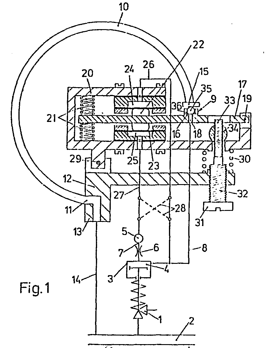
Description
Die Erfindung bezieht sich auf einen pneumatischen Druckschalter zum Steuern der Druckluftkammer von mediumdurchströmten Armaturen, insbesondere von zusatzbelasteten Sicherheitsventilen, wobei die Druckluftkammer über eine Luftzuführleitung an die Druckluftquelle und über eine Luftabführleitung an ein Auslaßventil angeschlossen ist, das einen größeren öffnungsquerschnitt als die gegebenenfalls gedrosselte Luftzuführleitung aufweist und von dem pneumatischen Druckschalter gesteuert wird, der ein an die Mediumdruckleitung angeschlossenes Dehnglied aufweist, dessen eines Ende fest am MediumanschluB sitzt und dessen freies druckdicht abgeschlossenes anderes Ende sich in Abhängigkeit vom Mediumdruck mehr oder weniger durch elastische Verformung bewegt.The invention relates to a pneumatic pressure switch for controlling the compressed air chamber of fittings through which medium flows, in particular safety valves loaded with additional loads, the compressed air chamber being connected via an air supply line to the compressed air source and via an air discharge line to an outlet valve which has a larger opening cross section than the possibly throttled air supply line and is controlled by the pneumatic pressure switch, which has an expansion element connected to the medium pressure line, one end of which is firmly seated on the medium connection and the free other end, which is closed in a pressure-tight manner, moves more or less by elastic deformation depending on the medium pressure.
Bei zusatzbelasteten Sicherheitsventilen sind pneumatische Druckschalter bekannt, bei denen das bewegliche freie Ende des als spiralförmiges Bourdonrohr ausgebildeten Dehngliedes eine Steuerfahne trägt, die einen von einer Strahldüse auf eine Fangdüse gerichteten Luftstrahl bei Erreichen des Ansprechdruckes unterbricht. Durch diese Unterbrechung des Luftstrahles wird ein mit der Fangdüse in Verbindung stehendes, als Membranventil ausgebildetes Auslaßventil in der Membrankammer entlastet, wodurch ein von einer Gegenfeder belasteter Ventilkörper die Druckluftkammer des Zusatzbelastungszylinders zur Atmosphäre hin öffnet.In the case of additional-loaded safety valves, pneumatic pressure switches are known in which the movable free end of the expansion element designed as a spiral Bourdon tube carries a control flag which interrupts an air jet directed from a jet nozzle onto a collecting nozzle when the response pressure is reached. This interruption of the air jet relieves an outlet valve in the membrane chamber which is connected to the catching nozzle and is designed as a diaphragm valve, as a result of which a valve body loaded by a counter spring opens the compressed air chamber of the additional loading cylinder to the atmosphere.
Da der Luftstrahl ständig ansteht, arbeitet dieser pneumatische Druckschalter mit dauernd hohem Luftverbrauch. Da die Steuerfahne bereits bei einem geringen Anstieg des Mediumdruckes den Luftstrahl über seinen vollen Durchmesser durchfahren muß, ist ein langer Stellweg pro Druckeinheit an der Steuerfahne erforderlich, was nur mit dem spiralförmig gewickelten und damit aufwendigen Bourdonrohr gelingt. Dieses spiralförmige Bourdonrohr hat sehr niedrige Eigenfrequenzen und kommt bei den auftretenden Erschütterungen und Pulsationen leicht ins Schwingen, wodurch es zu Schaltfehlern und auch zu Ausfällen an der Steuerfahne kommen kann.Since the air jet is constantly on, this pneumatic pressure switch works with constantly high air consumption. Since the control flag already has to pass through the air jet over its full diameter with a slight increase in the medium pressure, a long travel per pressure unit on the control flag is required, which is only possible with the spiral ge wrapped and thus elaborate Bourdon tube succeeds. This spiral Bourdon tube has very low natural frequencies and easily vibrates when vibrations occur, which can lead to switching errors and failures on the control flag.
Abgesehen hiervon müssen bei Verwendung der Steuerfahne als Druckschalter in besonderen Fällen zusätzliche Maßnähmen, wie Einbau von Zu- oder Abluftdrosseln oder Zwischenschaltung von Luftspeichern, getroffen werden, um das dymamische Verhalten des Sicherheitsventils den Erfordernissen der Anlage anzupassen.Apart from this, when using the control flag as a pressure switch, additional measures must be taken in special cases, such as installing supply or exhaust air throttles or interposing air reservoirs, in order to adapt the dynamic behavior of the safety valve to the requirements of the system.
Aufgabe der Erfindung ist es, den pneumatischen Druckschalter zum Steuern der Druckluftkammer von mediumdurchströmten Armaturen so zu verbessern, daß bei geringstem Luftverbrauch und hoher Schaltsicherheit ein schnelles Ansprechen der Armatur auf Druckänderungen ohne Uberreaktionen gewährleistet ist.The object of the invention is to improve the pneumatic pressure switch for controlling the compressed air chamber of fittings through which the medium flows so that, with the lowest air consumption and high switching reliability, a quick response of the fitting to pressure changes is ensured without overreactions.
Die Lösung dieser Aufgabe wird in den Patentansprüchen gesehen.The solution to this problem is seen in the claims.
Dadurch, daß gemäß den Merkmalen des Anspruchs 1 das bewegliche Ende des Dehngliedes als Verschlußglied des Auslaßventils ausgebildet ist, kann der Ventilsitz im Durchmesser so groß ausgebildet werden, daß der Sitzumfang bereits bei einem sehr kleinen Ventilhub, der nur etwa 1/5 bis 1/10 des Steuerfahnenweges beträgt, ausreicht, einen genügend großen Auslaßquerschnitt freizugeben. Das Dehnglied kann somit wesentlich steifer und weniger anfällig gegen Schwingungen und Pulsationen gestaltet werden. Da das Auslaßventil im Normalzustand geschlossen ist, tritt am Druckschalter kaum ein Luftverbrauch auf. Der nachgiebig an die Luftabführleitung zur Druckluftkammer angeschlossene Ventilsitz des Auslaßventils ist hierbei an einem mittels Anpaßfedern elastisch aufgehängten Träger vorgesehen, der von einer ersten Steuerluftkammer in Schließrichtung und von einer zweiten Steuerluftkammer entgegengesetzt verlagert werden kann, so daß sich der öffnungshub des Auslaßventils pro Druckanstiegseinheit im Gegensatz zu einem starren Ventilsitz vergrößert oder verkleinert.Characterized in that, according to the features of claim 1, the movable end of the expansion member is designed as a closure member of the exhaust valve, the valve seat can be made so large in diameter that the seat circumference even with a very small valve lift, which is only about 1/5 to 1 / 10 of the control flag path is sufficient to release a sufficiently large outlet cross-section. The expansion member can thus be made much stiffer and less susceptible to vibrations and pulsations. Since the outlet valve is closed in the normal state, hardly any air consumption occurs at the pressure switch. The valve seat of the exhaust valve, which is flexibly connected to the air discharge line to the compressed air chamber, is in this case provided on a support which is elastically suspended by means of adjusting springs and which is connected by a first control air chamber in the closing direction and by a second Control air chamber can be shifted in the opposite direction, so that the opening stroke of the exhaust valve per pressure increase unit increases or decreases in contrast to a rigid valve seat.
Da die eine Steuerluftkammer an die Druckluftquelle und die andere Druckluftkammer an die Luftabführleitung angeschlossen ist, ist der Hub des Auslaßventils nicht nur vom Mediumdruck, sondern auch vom Druck in der Luftabführleitung abhängig. Da andererseits der Hub des Auslaßventils den Druck in der Luftabführleitung bestimmt, wird eine Rückkopplung erzielt, die je nach Beaufschlagungsrichtung als Mit-oder als Gegenkopplung wirkt. Mit dieser Rückkopplung läßt sich das dynamische Schaltverhalten der Armatur wesentlich verändern. Ist beispielsweise die Reaktion des Verschlußkörpers eines Sicherheitsventils auf Mediumdruckänderungen zu langsam, kann durch eine entsprechend weichere Anpaßfeder und auch durch Umschaltung der Anschlüsse der Steuerluftkammer von Gegenkopplung auf Mitkopplung das gewünschte Ansprechverhalten des Ventils erzielt werden. Bei zu schnellem Ansprechen der Armatur läßt sich durch umgekehrtes Vorgehen ebenfalls eine feinstufige Anpassung an die gewünschte Ventilreaktion erreichen.Since one control air chamber is connected to the compressed air source and the other compressed air chamber is connected to the air discharge line, the stroke of the outlet valve is dependent not only on the medium pressure, but also on the pressure in the air discharge line. On the other hand, since the stroke of the exhaust valve determines the pressure in the air discharge line, feedback is achieved which, depending on the direction of action, acts as positive or negative feedback. With this feedback, the dynamic switching behavior of the valve can be changed significantly. If, for example, the reaction of the closure body of a safety valve to changes in medium pressure is too slow, the desired response behavior of the valve can be achieved by a correspondingly softer adjustment spring and also by switching the connections of the control air chamber from negative feedback to positive feedback. If the valve responds too quickly, the reverse procedure can also be used to achieve a fine adjustment to the desired valve reaction.
Durch den Anschluß der in Schließrichtung des Auslaßventils auf den Träger einwirkenden Steuerluftkammer an die Druckluftquelle und den Anschluß der anderen Steuerluftkammer an die Luftabführleitung gemäß Anspruch 2 wird eine Gegenkopplung des Luftabführleitungsdruckes erzielt, während bei dem umgekehrten Anschluß der Leitungen entsprechend Anspruch 3 eine Mitkopplung erfolgt.By connecting the control air chamber acting on the carrier in the closing direction of the outlet valve to the compressed air source and the connection of the other control air chamber to the air discharge line according to
Bei Armaturen mit größeren Druckluftkammern ist der öffnungsquerschnitt des Auslaßventils nicht groß genug, um die Luft aus der Druckluftkammer und die ständig-aus der Druckluftquelle nachströmende Luft schnell genug abzuführen. Deshalb wird gemäß Anspruch 4 vorgeschlagen, das Auslaßventil als Vorsteuerventil für ein als Membran- oder Kolbenventil ausgebildetes Servoventil zu verwenden, das im Querschnitt groß genug ausgebildet werden kann, damit die Luftmenge schnell genug entweichen kann und auch schnell genug wieder zugeführt wird.In valves with larger compressed air chambers, the opening cross section of the outlet valve is not large enough to discharge the air from the compressed air chamber and the air flowing in continuously from the compressed air source quickly enough. Of half is proposed according to
Durch die Merkmale des Anspruchs 5 ergibt sich eine besonders einfache Ausbildung des Servoventils als Zweiwegeventil, während bei dem als Dreiwegeventil ausgebildeten Servoventil nach Anspruch 6 der Vorteil darin liegt, daß bei einem zwar etwas größeren Aufwand die von der Druckluftquelle kommende Luft beim Entlüften ganz abgesperrt werden kann und nicht ständig nachströmt.The features of
Die Erfindung wird anhand von Ausführungsbeispielen in der Zeichnung näher erläutert, und zwar zeigt:
- Fig. 1 einen pneumatischen Druckschalter im Querschnitt mit angeschlossenem, nur schematisch dargestelltem zusatzbelasteten Sicherheitsventil,
- Fig. 2 den Druckschalter mit dem Sicherheitsventil nach Fig. 1 mit zwischengeschaltetem Servo- ventil,
- Fig. 3 die untere schematische Darstellung der Anschlüsse gemäß Fig. 2 mit einem anderen Servo- ventil,
- Fig. 4 eine abgeänderte Ausführung des Druckschalters in Vorderansicht,
- Fig. 5 einen Längsschnitt durch den Druckschalter nach Fig. 4 mit Doppelventilkegel und Handrad und
- Fig. 6 das Handrad nach Fig. 5 in Draufsicht.
- 1 shows a pneumatic pressure switch in cross section with a connected, only schematically shown, additional loaded safety valve,
- 2 shows the pressure switch with the safety valve according to FIG. 1 with an interposed servo valve,
- 3 shows the lower schematic representation of the connections according to FIG. 2 with another servo valve,
- 4 is a modified version of the pressure switch in front view,
- Fig. 5 shows a longitudinal section through the pressure switch according to Fig. 4 with double valve plug and handwheel and
- Fig. 6, the handwheel according to Fig. 5 in plan view.
Die Fig. 1 zeigt ein Sicherheitsventil 1, dessen Eintritt an die Mediumdruckleitung 2 angeschlossen ist und das einen Zusatzbelastungszylinder 3 mit Druckluftkammer 4 trägt. Die Druckluft wird von der Druckluftquelle 5 über die mit einer Drossel 6 versehene Luftzuführleitung 7 in die Druckluftkammer 4 des Sicherheitsventils 1 eingeführt. Zur Entlastung der Druckluftkammer 4 ist diese über die Luftabführleitung 8 an das Auslaßventil 9 angeschlossen.1 shows a safety valve 1, the inlet of which is connected to the
Das Auslaßventil 9 ist Bestandteil eines pneumatischen Druckschalters, dessen Dehnglied 10 an seinem festen Ende 11 im Lagerbock 12 des Druckschalters gehalten ist und über den Mediumanschluß 13 und die Verbindungsleitung 14 mit der Mediumdruckleitung 2 in offener Verbindung steht. Das sich unter der Einwirkung des Mediumdruckes bewegende freie Ende 15 des Dehngliedes 10 ist als Verschlußglied des Auslaßventils 9 ausgebildet. Der Ventilsitz 16 des Auslaßventils 9 wird durch den Rand einer in einen Träger 17 eingebrachten Bohrung 18 gebildet, an die die Luftabführleitung 8 nachgiebig angeschlossen ist. Der Träger 17 ist an seinem einen Ende im Gelenk 19 der Stütze 20 gelagert und ruht an seinem anderen Ende zwischen zwei von der Stütze'20 gehaltenen Anpaßfedern 21. Dadurch ist der Träger 17 mit seinem Ventilsitz 16 federnd beweglich gelagert. Der Träger 17 ist mit zwei symmetrischen Stütznoppen 22 versehen, die an den Membranen 23 der Steuerluftkammern 24 und 25 anliegen. Die Steuerluftkammer 24 steht über die Anschlußleitung 26 mit der Luftabführleitung 8 in offener Verbindung, während die Steuerluftkammer 25 über die Anschlußleitung 27 an die Druckluftquelle 5 angeschlossen ist. Soll anstelle der dargestellten Gegenkopplung eine Mitkopplung vorgesehen werden, so sind die Anschlußleitungen 26 und 27 für die Steuerluftkammern 24 und 25 durch die gestrichelt dargestellte Überkreuzschaltung 28 zu vertauschen.The
Um eine Feinseinstellung des Ansprechpunkts des Auslaßventils 9 zu ermöglichen, ist die Stütze 20 an ihrem einen Ende über das Gelenk 29 drehbar am Lagerbock 12 befestigt. An dem anderen beweglichen Ende der Stütze 20 sind zwischen Lagerbock 12 und Stütze 20 eine Stützfeder 30 und eine Stellschraube 31 vorgesehen. Die Stellschraube 31 besitzt zwei Gewindeabschnitte 32 und 33 mit gleichsinnigen, leicht unterschiedlichen Steigungen. Der Gewindeabschnitt 32 ist direkt in den Lagerbock 12 eingeschraubt, während der obere Gewindeabschnitt 33 in die Gelenkmutter 34 eingedreht ist. Am Auslaßventil 9 ist zwischen dem freien Ende 15 des Dehngliedes 10 und dem Ventilsitz 16 eine die Unparallelitäten ausgleichende Ventilkugel 35 vorgesehen, für deren Halterung der Führungskäfig 36 am Träger 17 dient.In order to enable a fine adjustment of the response point of the
Die Funktionsweise des in Fig. 1 dargestellten Druckschalters ist folgende:
- Im Normalzustand ist das Sicherheitsventil 1 geschlossen und im
Zusatzbelastungszylinder 3 steht Belastungsluft in derDruckluftkammer 4 an. übersteigt der Mediumdruck in derLeitung 2 den Ansprechdruck des Sicherheitsventils, so hebt sich dasfreie Ende 15 desDehngliedes 10 und damit dieVentilkugel 35, wodurch die Druckluft aus derDruckluftkammer 4 über dieLuftabführleitung 8 aus demAuslaßventil 9 ins Freie entweichen kann. Dadurch wird dieDruckluftkammer 4 soweit entlastet, daß das Sicherheitsventil 1 öffnet. Der öffnungsquerschnitt desAuslaßventils 9 ist größer als der Querschnitt der Drossel 6, so daß der Druck in derDruckluftkammer 4 trotz der ständig über die Drossel 6 aus derDruckluftquelle 5 zuströmenden Druckluft bis nahezu auf Null gesenkt werden kann.
- In the normal state, the safety valve 1 is closed and in the
additional loading cylinder 3 there is loading air in thecompressed air chamber 4. If the medium pressure inline 2 exceeds the response pressure of the safety valve, then thefree end 15 of theexpansion element 10 and thus thevalve ball 35 rise, as a result of which the compressed air from thecompressed air chamber 4 can escape from theoutlet valve 9 via theair discharge line 8. This relieves the pressure on thecompressed air chamber 4 to such an extent that the safety valve 1 opens. The opening cross section of theoutlet valve 9 is larger than the cross section of the throttle 6, so that the pressure in thecompressed air chamber 4 can be reduced to almost zero in spite of the compressed air flowing continuously from thecompressed air source 5 via the throttle 6.
Der öffnungs- und Schließvorgang des Sicherheitsventils 1 läßt sich durch die Steuerluftkammern 24 und 25 beeinflussen. Sind die Steuerluftkammern 24 und 25 wie dargestellt ange- w schlossen, so ist beim öffnen des Auslaßventils 9 die in Schließrichtung wirkende Kraft der Steuerluftkammer 25 größer als die entgegengesetzt wirkende Kraft der Steuerluftkammer 24, wodurch sich der Träger 17 mit dem Ventilsitz 16 in Ventilschließrichtung mitbewegt. Die Größe dieser Bewegung hängt ab von den geometrischen Abmessungen der Steuereinrichtung und kann leicht durch Austauschen der Anpaßfedern 21 verstärkt oder vermindert werden. Durch diese Gegenkopplung wird das Entlüften der Druckluftkammer 4 mehr oder weniger verlangsamt, wodurch beispielsweise bei großen Rohrleitungen Stoßbelastungen vermieden werden. Ist dagegen aus Sicherheitsgründen ein schnelles öffnen des Sicherheitsventils 1 erforderlich, so kann durch Umpolen der Anschlußleitungen 26 und 27 durch die Uberkreuzschaltung 28 eine Mitkopplung mit in öffnungsrichtung wanderndem Ventilsitz 16 erreicht werden.The opening and closing process of the safety valve 1 can be influenced by the
Bei dem Ausführungsbeispiel nach Fig. 2 dient das Auslaßventil 9 als Vorsteuerventil für das Servoventil 37. Dieses Servoventil ist als Dreiwegeventil ausgebildet und besitzt einen ersten Anschluß 38 zur Druckluftquelle 5 sowie einen zweiten Anschluß 39 zur Druckluftkammer 4. Außerdem ist ein in die Atmosphäre mündender Auslaß 40 vorgesehen. Der Steuerluftraum 41 des Servoventils 37 ist an die Luftabführleitung 8 angeschlossen und betätigt das Absperrorgan des Servoventils in der Weise, daß die Druckluftkammer 4 in der einen Ventilstellung mit der Druckluftquelle 5 und in der anderen Stellung mit der Atmosphäre verbunden ist. Die Luftabführleitung 8 ist hier über die Drossel 42 auch an die Druckluftquelle 5 angeschlossen.2, the
Die Fig. 3 zeigt ein anderes Servoventil 43, das als Zweiwegeventil ausgebildet ist und dessen Eintritt 44 mit der Druckluftkammer 4 in Verbindung steht und dessen Austritt 45 in die Atmosphäre mündet. Der Steuerluftraum 46 dieses Servoventils ist mit der Luftabführleitung 8 und über eine Drossel 47 mit der Druckluftquelle 5 verbunden. Die Drossel43 ist in die Luftzuführleitung 7 von der Druckluftquelle 5 zur-Druckluftkammer 4 eingesetzt. Beim öffnen des Auslaßventils 9 wird der Steuerluftraum 46 des Servoventils 43 entlastet, womit der Durchgang vom Eintritt 44 zum Atmosphärenaustritt 45 freigegeben und die Druckluftkammer 4 dadurch entlastet wird.3 shows another
Der in der Fig. 4 gezeigte pneumatische Druckschalter ist eine Variante des Druckschalters nach Fig. 1, wobei die wesentlichen Unterschiede darin bestehen, daß anstelle der zylindrischen Schraubendruckfedern 21 eine oder mehrere Blattfedern 49 als Anpaßfedern vorgesehen sind und anstelle des Gelenks 19 zwischen der Stütze 20 und dem Träger 17 ebenfalls eine Blattfeder 50 sitzt.The pneumatic pressure switch shown in FIG. 4 is a variant of the pressure switch according to FIG. 1, the main differences being that instead of the cylindrical helical compression springs 21, one or
Aus den Fig. 5 und 6 ist der in den Lagerbock 12 eingebaute Doppelventilkegel 51 ersichtlich, der in der einen Endlage den Anschluß 13 für die Mediumleitung 14 und in der anderen Endlage einen Prüfanschluß 52 für eine nicht näher dargestellte Prüfpumpe über den Zuführungskanal 53 mit dem Dehnglied 10 verbindet. Die Ventilspindel 54 des Doppelventilkegels 51 wird durch ein Handrad 55 betätigt, das über eine seitliche Verriegelungsnut 56 nur dann von der Ventilspindel 54 abnehmbar ist, wenn sich der Doppelventilkegel 51 in der für die Mediumleitung 13 offenen Frdlage befindet. Beim Einsatz mehrerer redundant angeordneter Druckschalter wird nur ein einziges Handrad 55 vorgesehen, so daß gewährleistet. ist, daß immer nur ein Druckschalter für Prüfzwecke von der Mediumleitung 13 auf den Prüfanschluß 52 umgeschaltet werden kann.5 and 6, the
Claims (12)
Priority Applications (1)
| Application Number | Priority Date | Filing Date | Title |
|---|---|---|---|
| AT86107773T ATE62761T1 (en) | 1985-06-07 | 1986-06-06 | PNEUMATIC PRESSURE SWITCH FOR CONTROLLING THE COMPRESSED AIR CHAMBER OF MEDIUM-FLOWED FITTINGS. |
Applications Claiming Priority (2)
| Application Number | Priority Date | Filing Date | Title |
|---|---|---|---|
| DE3520554 | 1985-06-07 | ||
| DE19853520554 DE3520554A1 (en) | 1985-06-07 | 1985-06-07 | PNEUMATIC PRESSURE SWITCH FOR CONTROLLING THE COMPRESSED AIR CHAMBER OF MEDIUM-FLOWED FITTINGS |
Publications (3)
| Publication Number | Publication Date |
|---|---|
| EP0205129A2 true EP0205129A2 (en) | 1986-12-17 |
| EP0205129A3 EP0205129A3 (en) | 1987-07-22 |
| EP0205129B1 EP0205129B1 (en) | 1991-04-17 |
Family
ID=6272760
Family Applications (1)
| Application Number | Title | Priority Date | Filing Date |
|---|---|---|---|
| EP86107773A Expired - Lifetime EP0205129B1 (en) | 1985-06-07 | 1986-06-06 | Pneumatic pressure switch for controlling the air pressure-chamber of fluid-floaded armatures |
Country Status (3)
| Country | Link |
|---|---|
| EP (1) | EP0205129B1 (en) |
| AT (1) | ATE62761T1 (en) |
| DE (1) | DE3520554A1 (en) |
Cited By (3)
| Publication number | Priority date | Publication date | Assignee | Title |
|---|---|---|---|---|
| GB2255424A (en) * | 1991-05-03 | 1992-11-04 | Delta Eng Holdings Ltd | Fluid flow control valves |
| WO2008042862A3 (en) * | 2006-10-02 | 2008-07-31 | Fisher Controls Int | Low consumption pneumatic controller |
| WO2008042861A3 (en) * | 2006-10-02 | 2008-09-12 | Fisher Controls Int | Low consumption pneumatic controller |
Families Citing this family (2)
| Publication number | Priority date | Publication date | Assignee | Title |
|---|---|---|---|---|
| DE3738630C2 (en) * | 1987-11-13 | 1995-06-08 | Rexroth Mannesmann Gmbh | Electro-hydraulic pressure converter device |
| CN120739925B (en) * | 2025-09-03 | 2025-10-31 | 四川中油乐仪能源装备制造股份有限公司 | Pilot-operated safety valve |
Family Cites Families (5)
| Publication number | Priority date | Publication date | Assignee | Title |
|---|---|---|---|---|
| DE539974C (en) * | 1930-12-14 | 1931-12-12 | Selbsttaetige Temperaturregelu | Regulator |
| US2268783A (en) * | 1939-03-17 | 1942-01-06 | Baldwin Locomotive Works | Indicating apparatus |
| DE1221068B (en) * | 1963-05-04 | 1966-07-14 | Bopp & Reuther Gmbh | Safety valve with controlled additional load |
| DE1199090B (en) * | 1963-08-03 | 1965-08-19 | Bopp & Reuther Gmbh | Safety valve with controlled additional load |
| DE2643527C3 (en) * | 1976-09-28 | 1980-05-14 | Bopp & Reuther Gmbh, 6800 Mannheim | Switching mechanism, in particular for controlling the load air from additionally loaded safety valves |
-
1985
- 1985-06-07 DE DE19853520554 patent/DE3520554A1/en active Granted
-
1986
- 1986-06-06 AT AT86107773T patent/ATE62761T1/en not_active IP Right Cessation
- 1986-06-06 EP EP86107773A patent/EP0205129B1/en not_active Expired - Lifetime
Cited By (5)
| Publication number | Priority date | Publication date | Assignee | Title |
|---|---|---|---|---|
| GB2255424A (en) * | 1991-05-03 | 1992-11-04 | Delta Eng Holdings Ltd | Fluid flow control valves |
| WO2008042862A3 (en) * | 2006-10-02 | 2008-07-31 | Fisher Controls Int | Low consumption pneumatic controller |
| WO2008042861A3 (en) * | 2006-10-02 | 2008-09-12 | Fisher Controls Int | Low consumption pneumatic controller |
| CN101523321B (en) * | 2006-10-02 | 2013-04-03 | 费希尔控制产品国际有限公司 | Low consumption pneumatic controller |
| CN101523320B (en) * | 2006-10-02 | 2015-09-02 | 费希尔控制产品国际有限公司 | Low consumption pneumatic controller |
Also Published As
| Publication number | Publication date |
|---|---|
| EP0205129B1 (en) | 1991-04-17 |
| EP0205129A3 (en) | 1987-07-22 |
| DE3520554C2 (en) | 1989-04-06 |
| ATE62761T1 (en) | 1991-05-15 |
| DE3520554A1 (en) | 1986-12-11 |
Similar Documents
| Publication | Publication Date | Title |
|---|---|---|
| DE69921434T2 (en) | Flow control valve | |
| DE1090478B (en) | Pressure regulator with a spring-loaded control pressure regulator located in a secondary line | |
| DE2748079C2 (en) | Water pressure booster system | |
| AT389622B (en) | THE OPERATING PRESSURE FOR MILKING SYSTEMS AUTOMATICALLY REGULATING VALVE | |
| LU84377A1 (en) | ADJUSTABLE THROTTLE VALVE | |
| EP0205129A2 (en) | Pneumatic pressure switch for controlling the air pressure-chamber of fluid-floaded armatures | |
| DE102016002834B4 (en) | Valve with a monitoring function | |
| EP0006416A1 (en) | Two-stage gas valve | |
| DE4320937A1 (en) | Actuator for a control valve | |
| DE1917079C3 (en) | Pneumatic amplifier | |
| DE2308333A1 (en) | CONTROL VALVE | |
| DE29710127U1 (en) | Electro-hydraulic clamping device | |
| DE8516725U1 (en) | Pneumatic pressure switch for controlling the compressed air chamber of medium-flow fittings | |
| EP1832950A1 (en) | Control system for controlling the fluid operating pressure | |
| EP0075969B1 (en) | Levelling valve for load-responsive vehicle air spring devices | |
| DE3227116C2 (en) | Pressure control valve for liquids | |
| DE2158201B2 (en) | PRESSURE REGULATING VALVE | |
| DE2359470C3 (en) | Pressure reducing valve | |
| DE4209736C2 (en) | Pressure regulator with a display device operating without auxiliary energy | |
| DE1177951B (en) | Control device for damping devices with electrically changeable damping value, especially in motor vehicles | |
| DE2231233C3 (en) | Gas switch | |
| DE2345864C3 (en) | Pressure reducing valve | |
| DE1600937C3 (en) | Gas cylinder valve for attachable membrane pressure regulators | |
| EP0111647A1 (en) | Valve device | |
| DE102005008763A1 (en) | Pressure valve assembly for hydraulic clamping mechanisms has pressure reducing valve with regulating piston loaded in opening direction by regulating spring whose pretension is hydraulically changed to set different clamping pressures |
Legal Events
| Date | Code | Title | Description |
|---|---|---|---|
| PUAI | Public reference made under article 153(3) epc to a published international application that has entered the european phase |
Free format text: ORIGINAL CODE: 0009012 |
|
| AK | Designated contracting states |
Kind code of ref document: A2 Designated state(s): AT BE CH FR GB IT LI NL SE |
|
| PUAL | Search report despatched |
Free format text: ORIGINAL CODE: 0009013 |
|
| AK | Designated contracting states |
Kind code of ref document: A3 Designated state(s): AT BE CH FR GB IT LI NL SE |
|
| 17P | Request for examination filed |
Effective date: 19880119 |
|
| 17Q | First examination report despatched |
Effective date: 19891115 |
|
| GRAA | (expected) grant |
Free format text: ORIGINAL CODE: 0009210 |
|
| AK | Designated contracting states |
Kind code of ref document: B1 Designated state(s): AT BE CH FR GB IT LI NL SE |
|
| PG25 | Lapsed in a contracting state [announced via postgrant information from national office to epo] |
Ref country code: IT Free format text: LAPSE BECAUSE OF FAILURE TO SUBMIT A TRANSLATION OF THE DESCRIPTION OR TO PAY THE FEE WITHIN THE PRE;WARNING: LAPSES OF ITALIAN PATENTS WITH EFFECTIVE DATE BEFORE 2007 MAY HAVE OCCURRED AT ANY TIME BEFORE 2007. THE CORRECT EFFECTIVE DATE MAY BE DIFFERENT FROM THE ONE RECORDED.SCRIBED TIME-LIMIT Effective date: 19910417 Ref country code: GB Effective date: 19910417 Ref country code: SE Effective date: 19910417 Ref country code: NL Effective date: 19910417 Ref country code: BE Effective date: 19910417 |
|
| REF | Corresponds to: |
Ref document number: 62761 Country of ref document: AT Date of ref document: 19910515 Kind code of ref document: T |
|
| PG25 | Lapsed in a contracting state [announced via postgrant information from national office to epo] |
Ref country code: AT Effective date: 19910606 |
|
| PG25 | Lapsed in a contracting state [announced via postgrant information from national office to epo] |
Ref country code: LI Effective date: 19910630 Ref country code: CH Effective date: 19910630 |
|
| EN | Fr: translation not filed | ||
| PG25 | Lapsed in a contracting state [announced via postgrant information from national office to epo] |
Ref country code: FR Effective date: 19910906 |
|
| NLV1 | Nl: lapsed or annulled due to failure to fulfill the requirements of art. 29p and 29m of the patents act | ||
| GBV | Gb: ep patent (uk) treated as always having been void in accordance with gb section 77(7)/1977 [no translation filed] | ||
| PLBE | No opposition filed within time limit |
Free format text: ORIGINAL CODE: 0009261 |
|
| STAA | Information on the status of an ep patent application or granted ep patent |
Free format text: STATUS: NO OPPOSITION FILED WITHIN TIME LIMIT |
|
| REG | Reference to a national code |
Ref country code: CH Ref legal event code: PL |
|
| 26N | No opposition filed | ||
| REG | Reference to a national code |
Ref country code: FR Ref legal event code: ST |