EP0204664A1 - Motor vehicle gearbox with constantly-meshed gears - Google Patents
Motor vehicle gearbox with constantly-meshed gears Download PDFInfo
- Publication number
- EP0204664A1 EP0204664A1 EP86830128A EP86830128A EP0204664A1 EP 0204664 A1 EP0204664 A1 EP 0204664A1 EP 86830128 A EP86830128 A EP 86830128A EP 86830128 A EP86830128 A EP 86830128A EP 0204664 A1 EP0204664 A1 EP 0204664A1
- Authority
- EP
- European Patent Office
- Prior art keywords
- reverse
- engagement
- coupling sleeve
- shaft
- selector rod
- Prior art date
- Legal status (The legal status is an assumption and is not a legal conclusion. Google has not performed a legal analysis and makes no representation as to the accuracy of the status listed.)
- Granted
Links
- 230000008878 coupling Effects 0.000 claims abstract description 26
- 238000010168 coupling process Methods 0.000 claims abstract description 26
- 238000005859 coupling reaction Methods 0.000 claims abstract description 26
- 230000033001 locomotion Effects 0.000 claims abstract description 15
- 230000000694 effects Effects 0.000 claims abstract description 5
- 230000007935 neutral effect Effects 0.000 claims description 8
- 230000003993 interaction Effects 0.000 description 1
Images

Classifications
-
- F—MECHANICAL ENGINEERING; LIGHTING; HEATING; WEAPONS; BLASTING
- F16—ENGINEERING ELEMENTS AND UNITS; GENERAL MEASURES FOR PRODUCING AND MAINTAINING EFFECTIVE FUNCTIONING OF MACHINES OR INSTALLATIONS; THERMAL INSULATION IN GENERAL
- F16D—COUPLINGS FOR TRANSMITTING ROTATION; CLUTCHES; BRAKES
- F16D23/00—Details of mechanically-actuated clutches not specific for one distinct type
- F16D23/02—Arrangements for synchronisation, also for power-operated clutches
- F16D23/04—Arrangements for synchronisation, also for power-operated clutches with an additional friction clutch
- F16D23/06—Arrangements for synchronisation, also for power-operated clutches with an additional friction clutch and a blocking mechanism preventing the engagement of the main clutch prior to synchronisation
-
- F—MECHANICAL ENGINEERING; LIGHTING; HEATING; WEAPONS; BLASTING
- F16—ENGINEERING ELEMENTS AND UNITS; GENERAL MEASURES FOR PRODUCING AND MAINTAINING EFFECTIVE FUNCTIONING OF MACHINES OR INSTALLATIONS; THERMAL INSULATION IN GENERAL
- F16H—GEARING
- F16H3/00—Toothed gearings for conveying rotary motion with variable gear ratio or for reversing rotary motion
- F16H3/02—Toothed gearings for conveying rotary motion with variable gear ratio or for reversing rotary motion without gears having orbital motion
- F16H3/20—Toothed gearings for conveying rotary motion with variable gear ratio or for reversing rotary motion without gears having orbital motion exclusively or essentially using gears that can be moved out of gear
- F16H3/38—Toothed gearings for conveying rotary motion with variable gear ratio or for reversing rotary motion without gears having orbital motion exclusively or essentially using gears that can be moved out of gear with synchro-meshing
- F16H3/385—Toothed gearings for conveying rotary motion with variable gear ratio or for reversing rotary motion without gears having orbital motion exclusively or essentially using gears that can be moved out of gear with synchro-meshing with braking means
-
- F—MECHANICAL ENGINEERING; LIGHTING; HEATING; WEAPONS; BLASTING
- F16—ENGINEERING ELEMENTS AND UNITS; GENERAL MEASURES FOR PRODUCING AND MAINTAINING EFFECTIVE FUNCTIONING OF MACHINES OR INSTALLATIONS; THERMAL INSULATION IN GENERAL
- F16H—GEARING
- F16H63/00—Control outputs from the control unit to change-speed- or reversing-gearings for conveying rotary motion or to other devices than the final output mechanism
- F16H63/02—Final output mechanisms therefor; Actuating means for the final output mechanisms
- F16H63/30—Constructional features of the final output mechanisms
- F16H63/302—Final output mechanisms for reversing
-
- F—MECHANICAL ENGINEERING; LIGHTING; HEATING; WEAPONS; BLASTING
- F16—ENGINEERING ELEMENTS AND UNITS; GENERAL MEASURES FOR PRODUCING AND MAINTAINING EFFECTIVE FUNCTIONING OF MACHINES OR INSTALLATIONS; THERMAL INSULATION IN GENERAL
- F16D—COUPLINGS FOR TRANSMITTING ROTATION; CLUTCHES; BRAKES
- F16D23/00—Details of mechanically-actuated clutches not specific for one distinct type
- F16D23/02—Arrangements for synchronisation, also for power-operated clutches
- F16D23/04—Arrangements for synchronisation, also for power-operated clutches with an additional friction clutch
- F16D23/06—Arrangements for synchronisation, also for power-operated clutches with an additional friction clutch and a blocking mechanism preventing the engagement of the main clutch prior to synchronisation
- F16D2023/0618—Details of blocking mechanism comprising a helical spring loaded element, e.g. ball
Definitions
- the present invention relates to motor vehicle gearboxes in general.
- the invention concerns a gearbox of the type comprising a shaft and a layshaft carrying respective constantly-meshed gears, and a reversing shaft carrying a slidable idler gear arranged for meshing with respective reverse gears carried by the shaft and the-layshaft, and in which a selector rod is provided which is movable axially in opposite directions relative to a neutral intermediate position to effect the engagement of the highest ratio and reverse respectively by means of respective control forks, of which that for reverse acts on the idler gear and that for the highest ratio is fitted to a grooved slidable coupling sleeve having internal teeth slidably engaged with a toothed hub rigid with the gear shaft.
- a gearbox of this type is described and illustrated, for example, in Italian utility model application no. 53633-A/84 in the name of the present applicants.
- the object of the present invention is to avoid this disadvantage and to achieve a motor vehicle gearbox of the type defined at the beginning, which is provided in a simple and cheap manner with an 'effective system for synchronising the shaft and the layshaft upon the engagement of reverse.
- this object is achieved by virtue of the fact that the mutual coupling surfaces of the control fork for the highest ratio and the slidable coupling sleeve are conical surfaces which diverge in the direction of movement of the selector rod corresponding to the engagement of reverse, and in that means are provided for opposing the sliding of the slidable coupling sleeve relative to the toothed hub in the direction of movement of the selector rod corresponding to the engagement of reverse.
- the opposing means of the slidable coupling sleeve include a synchronising roller interposed between the coupling sleeve and the toothed hub and biased by a spring into engagement with an internal annular groove in the coupling sleeve.
- This groove conveniently has an asymmetric profile with the side wall which faces in the opposite direction from the direction of movement of the selector rod corresponding to the engagement of reverse having a steeper inclination than the opposite side wall.
- the shaft and layshaft of a motor vehicle gearbox with constantly-meshed gears are indicated 1 and 2 respectively.
- the gearbox is of generally known type and therefore will not be described in detail.
- a gear 3 corresponding to the highest ratio that is the fifth gear in the case of a five-speed gearbox, is rotatably mounted on the shaft 1 and meshes with a corresponding gear for the highest ratio, not illustrated, keyed onto the layshaft 2.
- an internally-toothed coupling sleeve 4 which meshes in slidable manner with a toothed hub 5 keyed onto the shaft 3 and is movable axially, in the manner explained below, between a position of disengagement of the highest ratio, illustrated in Figure 1 and also in Figures 3 and 4, and a position of engagement of the highest ratio, illustrated in Figure 5, in which the coupling sleeve 4 engages a ring 'gear 6 rigid with the gear 3 so as to render this gear 3 fast for rotation with the toothed hub 5 and consequently with the shaft 1.
- a reverse gear 7 is also keyed onto the shaft 1 and a corresponding reverse gear 8 is keyed onto the layshaft 2.
- the reverse gears 7 and 8 can be connected together by means of an idler gear 9 slidably mounted on a reversing shaft 10 parallel to the shaft 1 and the layshaft 2.
- the idler gear 9 is movable between a rest position, illustrated in full outline in Figure 1, in which the reverse gears 7 and 8 are disconnected from each other and an operative position, illustrated in broken outline in Figure 1, in which it connects the gears 7 and 8 for rotation.
- a single selector rod 11 is provided which is parallel to the shafts 1, 2 and 10 and is movable axially in opposite directions from an intermediate neutral position, illustrated in Figure 1, to respective positions for engaging the highest ratio (towards the left with respect Figure 1) and for engaging reverse (towards the right with respect to Figure 1).
- a snap-positioning device 12 is provided which cooperates with corresponding notches 13 in the rod itself.
- the coupling sleeve 4 has a circumferential groove 14 in which a control fork 15 fixed to the rod 11 isengaged, while the idler gear 9 is coupled in the manner illustrated to a fork 16 pivotable about a transverse pin 17 carried by the fixed structure of the gearbox and having a part 18 engaged in a groove 19 of a sleeve member 20 slidable on the rod 11.
- One-way locking means are provided for locking the sleeve member 20 to the rod 11 when the latter is moved towards the right with respect to Figure 1, that is from its neutral position to the operative position corresponding to the engagement of reverse, and for allowing the rod 11 to slide relative to the sleeve member 20 when the rod 11 is moved towards the left with respect to Figure 1, that is from its neutral position to the operative position corresponding to the engagement of the fifth gear.
- These one-way lacking means are described and illustrated, for example, in Italian utility model application no. 53633-B/84 in the name of the applicants.
- control fork 15 for the highest ratio and the groove 14 of the coupling sleeve 4 have respective mutual coupling surfaces 15a and 14a which are conical in shape and diverge in the direction of movement of the selector rod 11 corresponding to the engagement of reverse, that is towards the right with respect to Figure 1.
- this direction is indicated by the arrow F in Figure 1.
- a synchronising roller 21 interposed between the coupling sleeve 4 and the toothed hub 5 and biased into engagement with an internal annular groove 23 in the coupling sleeve 4 by a radial spring 22.
- the groove 23 has an asymmetric profile with one side wall 23a having a less marked and more gradual inclination than the opposite side wall 23b which is almost radial.
- This tendency of the sleeve 4 is opposed initially, however, by the presence of the roller 21 which is engaged in the groove 23 under the action of the spring 22 and bears against the steeper wall 23b of this groove 23.
- the biasing action exerted by the roller 21 facilitates the interaction between the conical surfaces 15a and 14a and the generation of a braking action on the coupling sleeve 4 by the fork 15 and hence on the gear shaft 1 through the toothed hub 5.
- This braking action facilitates the correct meshing initially between the idler gear 9 and the reverse gear 7 and subsequently between the idler gear 9 and the reverse gear 8 carried by the layshaft 2.
Landscapes
- Engineering & Computer Science (AREA)
- General Engineering & Computer Science (AREA)
- Mechanical Engineering (AREA)
- Gear-Shifting Mechanisms (AREA)
- Structure Of Transmissions (AREA)
Abstract
Description
- The present invention relates to motor vehicle gearboxes in general.
- In particular, the invention concerns a gearbox of the type comprising a shaft and a layshaft carrying respective constantly-meshed gears, and a reversing shaft carrying a slidable idler gear arranged for meshing with respective reverse gears carried by the shaft and the-layshaft, and in which a selector rod is provided which is movable axially in opposite directions relative to a neutral intermediate position to effect the engagement of the highest ratio and reverse respectively by means of respective control forks, of which that for reverse acts on the idler gear and that for the highest ratio is fitted to a grooved slidable coupling sleeve having internal teeth slidably engaged with a toothed hub rigid with the gear shaft.
- A gearbox of this type is described and illustrated, for example, in Italian utility model application no. 53633-A/84 in the name of the present applicants.
- In motor vehicle gearboxes of the type defined above, the correct meshing of the idler gear and the respective reverse gears carried by the shaft and the layshaft presents difficulties whenever reverse is engaged by axial movement of the idler gear by the respective fork controlled by the selector rod. In fact, in these circumstances, while the layshaft and the idler gear are normally stationary, the gear shaft has a certain angular velocity which must be transmitted to the idler gear and then to the gear of the layshaft upon engagement of reverse. This may cause difficulties of meshing initially between the teeth of the idler gear and that carried by the shaft, and subsequently between the teeth of the idler gear and the gear carried by the layshaft, with consequent irritating noises.
- The object of the present invention is to avoid this disadvantage and to achieve a motor vehicle gearbox of the type defined at the beginning, which is provided in a simple and cheap manner with an 'effective system for synchronising the shaft and the layshaft upon the engagement of reverse.
- According to the invention, this object is achieved by virtue of the fact that the mutual coupling surfaces of the control fork for the highest ratio and the slidable coupling sleeve are conical surfaces which diverge in the direction of movement of the selector rod corresponding to the engagement of reverse, and in that means are provided for opposing the sliding of the slidable coupling sleeve relative to the toothed hub in the direction of movement of the selector rod corresponding to the engagement of reverse.
- By virtue of this solution, when the idler gear moves into mesh with the reverse gears of the shaft and the layshaft of the gearbox, braking of the shaft is achieved by virtue of the interference between the conical surfaces, which enables the easy and safe engagement of the teeth of the idler gear with those of the reverse gears carried by the shaft and the layshaft of the gearbox to be ensured.
- According to the invention, the opposing means of the slidable coupling sleeve include a synchronising roller interposed between the coupling sleeve and the toothed hub and biased by a spring into engagement with an internal annular groove in the coupling sleeve.
- This groove conveniently has an asymmetric profile with the side wall which faces in the opposite direction from the direction of movement of the selector rod corresponding to the engagement of reverse having a steeper inclination than the opposite side wall.
- The invention will now be described in detail with reference to the appended drawings, provided purely by way of non-limiting example, in which:
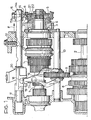
- Figure 1 is a partially-sectioned, schematic longitudinal view of a motor vehicle gearbox according to the invention,
- Figure 2 illustrates a detail of Figure 1 on an enlarged scale, and
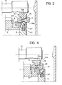
- Figures 3 to 5 show the same detail in three different operating conditions of the gearbox.
- With reference initially to Figure 1, the shaft and layshaft of a motor vehicle gearbox with constantly-meshed gears are indicated 1 and 2 respectively. The gearbox is of generally known type and therefore will not be described in detail. For the purposes of the present invention it suffices to say that a
gear 3 corresponding to the highest ratio, that is the fifth gear in the case of a five-speed gearbox, is rotatably mounted on the shaft 1 and meshes with a corresponding gear for the highest ratio, not illustrated, keyed onto the layshaft 2. In order to render thegear 3 fast for rotation with the shaft 1, an internally-toothed coupling sleeve 4 is provided which meshes in slidable manner with atoothed hub 5 keyed onto theshaft 3 and is movable axially, in the manner explained below, between a position of disengagement of the highest ratio, illustrated in Figure 1 and also in Figures 3 and 4, and a position of engagement of the highest ratio, illustrated in Figure 5, in which thecoupling sleeve 4 engages a ring 'gear 6 rigid with thegear 3 so as to render thisgear 3 fast for rotation with thetoothed hub 5 and consequently with the shaft 1. - A reverse gear 7 is also keyed onto the shaft 1 and a corresponding reverse gear 8 is keyed onto the layshaft 2. The reverse gears 7 and 8 can be connected together by means of an
idler gear 9 slidably mounted on a reversingshaft 10 parallel to the shaft 1 and the layshaft 2. In the manner explained below, theidler gear 9 is movable between a rest position, illustrated in full outline in Figure 1, in which the reverse gears 7 and 8 are disconnected from each other and an operative position, illustrated in broken outline in Figure 1, in which it connects the gears 7 and 8 for rotation. - In order to effect the engagement of the highest ratio or reverse, a
single selector rod 11 is provided which is parallel to theshafts 1, 2 and 10 and is movable axially in opposite directions from an intermediate neutral position, illustrated in Figure 1, to respective positions for engaging the highest ratio (towards the left with respect Figure 1) and for engaging reverse (towards the right with respect to Figure 1). In order to ensure the secure location of the selector rod 1 in the chosen position, a snap-positioning device 12 is provided which cooperates withcorresponding notches 13 in the rod itself. - The movement of the
rod 11 into one or other of the positions of engagement of the highest ratio or reverse causes a corresponding movement of thecoupling sleeve 4 or theidler gear 9 respectively. In fact, thecoupling sleeve 4 has acircumferential groove 14 in which acontrol fork 15 fixed to therod 11 isengaged, while theidler gear 9 is coupled in the manner illustrated to afork 16 pivotable about a transverse pin 17 carried by the fixed structure of the gearbox and having apart 18 engaged in agroove 19 of asleeve member 20 slidable on therod 11. One-way locking means, not illustrated, are provided for locking thesleeve member 20 to therod 11 when the latter is moved towards the right with respect to Figure 1, that is from its neutral position to the operative position corresponding to the engagement of reverse, and for allowing therod 11 to slide relative to thesleeve member 20 when therod 11 is moved towards the left with respect to Figure 1, that is from its neutral position to the operative position corresponding to the engagement of the fifth gear. These one-way lacking means are described and illustrated, for example, in Italian utility model application no. 53633-B/84 in the name of the applicants. - According to the invention, the
control fork 15 for the highest ratio and thegroove 14 of thecoupling sleeve 4 have respectivemutual coupling surfaces selector rod 11 corresponding to the engagement of reverse, that is towards the right with respect to Figure 1. For convenience, this direction is indicated by the arrow F in Figure 1. - Also in accordance with the invention, means are provided for opposing the sliding of the
sleeve 4 relative to thetoothed hub 5 in the same direction F. In the example illustrated, these opposing means are constituted by asynchronising roller 21 interposed between thecoupling sleeve 4 and thetoothed hub 5 and biased into engagement with an internalannular groove 23 in thecoupling sleeve 4 by aradial spring 22. As illustrated in greater detail in Figure 2, thegroove 23 has an asymmetric profile with oneside wall 23a having a less marked and more gradual inclination than theopposite side wall 23b which is almost radial. - As will be apparent, whenever the
selector rod 11 is moved in the direction of the arrow F from its neutral intermediate position towards the position of engagement of reverse, thesleeve member 20 moves in the same direction to effect pivoting of thefork 16 about the pin 17 and sliding of theidler gear 9 along theshaft 10 towards the position of engagement of the gears 7 and 8. Simultaneously, the movement of theselector rod 11 causes a corresponding movement of thefork 15 which initially brings theconical surface 15a into interference with theconical surface 14a of thesleeve 4. In this situation, thesleeve 4 also tends to move in the direction of the arrow F with respect to the central position illustrated in Figure 1 and Figure 3 (the neutral position). This tendency of thesleeve 4 is opposed initially, however, by the presence of theroller 21 which is engaged in thegroove 23 under the action of thespring 22 and bears against thesteeper wall 23b of thisgroove 23. The biasing action exerted by theroller 21 facilitates the interaction between theconical surfaces coupling sleeve 4 by thefork 15 and hence on the gear shaft 1 through thetoothed hub 5. This braking action facilitates the correct meshing initially between theidler gear 9 and the reverse gear 7 and subsequently between theidler gear 9 and the reverse gear 8 carried by the layshaft 2. - Naturally, during further movement of the
selector rod 11 in the direction of the arrow F, theopposing roller 21 is disengaged from thegroove 23 whereby thecoupling sleeve 4 is drawn to the position illustrated in Figure 4, corresponding to the condition of engagement of the reverse. - However, when the
selector rod 11 is moved in the direction opposite the arrow F from its neutral central position illustrated in Figures 1 and 3, that is in the direction corresponding to the engagement of the highest ratio, theopposing roller 21 acts on thesleeve 4, gradually being released from thegroove 23 along the more gently slopingwall 23a thereof. At the end of this movement of theselector rod 11, thecoupling sleeve 4 is located in the position illustrated in Figure 5, corresponding in fact to the engagement of the highest ratio. During this operation, thesleeve member 20 is kept stationary while theselector rod 11 slides within it, so that theidler gear 9 does not move along the reversingshaft 10. - Naturally the constructional details and forms of embodiment may be varied widely with respect to that described and illustrated, without thereby departing from the scope of the present invention.
Claims (3)
Applications Claiming Priority (2)
| Application Number | Priority Date | Filing Date | Title |
|---|---|---|---|
| IT67514/85A IT1185796B (en) | 1985-06-04 | 1985-06-04 | GEAR SPEED ALWAYS IN MILL FOR VEHICLES |
| IT6751485 | 1985-06-04 |
Publications (2)
| Publication Number | Publication Date |
|---|---|
| EP0204664A1 true EP0204664A1 (en) | 1986-12-10 |
| EP0204664B1 EP0204664B1 (en) | 1989-03-15 |
Family
ID=11303062
Family Applications (1)
| Application Number | Title | Priority Date | Filing Date |
|---|---|---|---|
| EP86830128A Expired EP0204664B1 (en) | 1985-06-04 | 1986-05-19 | Motor vehicle gearbox with constantly-meshed gears |
Country Status (4)
| Country | Link |
|---|---|
| EP (1) | EP0204664B1 (en) |
| DE (1) | DE3662448D1 (en) |
| ES (1) | ES8703352A1 (en) |
| IT (1) | IT1185796B (en) |
Cited By (7)
| Publication number | Priority date | Publication date | Assignee | Title |
|---|---|---|---|---|
| US4836041A (en) * | 1987-07-13 | 1989-06-06 | Fiat Auto S.P.A. | Motor vehicle gearbox with a device for synchronised engagement of reverse |
| FR2702263A1 (en) * | 1993-03-02 | 1994-09-09 | Peugeot | Device for operating a gearbox |
| DE19541843A1 (en) * | 1995-11-09 | 1997-05-15 | Steyr Daimler Puch Ag | Positive clutch with self-locking shifting |
| FR2852646A1 (en) * | 2003-03-20 | 2004-09-24 | Peugeot Citroen Automobiles Sa | Synchronizer for motor vehicle, has radial pusher forming units with case that closes elastic unit, and rolling unit projecting from case such that lateral surface is solicited on protecting ramp in rest position of sleeve |
| FR2959543A1 (en) * | 2010-04-29 | 2011-11-04 | Peugeot Citroen Automobiles Sa | Synchronizing device for manual gearbox of motor vehicle, has sleeve acting on levers during displacement in sleeve separating direction, to pivot levers to exert force on pushers to displace ring in direction of separating ring from hub |
| EP2314894A3 (en) * | 2009-10-23 | 2014-01-29 | Schaeffler Technologies AG & Co. KG | Synchronising device |
| CN104369787A (en) * | 2014-11-12 | 2015-02-25 | 长沙星聚农业机械有限公司 | Externally-hung reversion device |
Citations (6)
| Publication number | Priority date | Publication date | Assignee | Title |
|---|---|---|---|---|
| FR1359905A (en) * | 1963-03-22 | 1964-04-30 | Ferodo Sa | Device to facilitate engagement in a gearbox |
| DE2319397A1 (en) * | 1973-04-17 | 1974-10-24 | Ford Werke Ag | SYNCHRONIZATION DEVICE FOR THE REVERSE GEAR OF A MOTOR VEHICLE GEARBOX |
| FR2378215A1 (en) * | 1977-01-19 | 1978-08-18 | Peugeot | GEARBOX EQUIPPED WITH INPUT SHAFT BRAKING MEANS, FOR ENGAGING A NON-SYNCHRONIZED GEAR |
| EP0025734A2 (en) * | 1979-09-05 | 1981-03-25 | Automobiles Citroen | Control device for a multiple gear ratio and one reverse gear-box |
| GB2110778A (en) * | 1981-12-03 | 1983-06-22 | Ford Motor Co | Facilitating selection of reverse gear |
| US4503957A (en) * | 1982-03-09 | 1985-03-12 | Toyota Jidosha Kabushiki Kaisha | Shift mechanism in a manual transmission |
-
1985
- 1985-06-04 IT IT67514/85A patent/IT1185796B/en active
-
1986
- 1986-05-19 EP EP86830128A patent/EP0204664B1/en not_active Expired
- 1986-05-19 DE DE8686830128T patent/DE3662448D1/en not_active Expired
- 1986-06-03 ES ES555643A patent/ES8703352A1/en not_active Expired
Patent Citations (6)
| Publication number | Priority date | Publication date | Assignee | Title |
|---|---|---|---|---|
| FR1359905A (en) * | 1963-03-22 | 1964-04-30 | Ferodo Sa | Device to facilitate engagement in a gearbox |
| DE2319397A1 (en) * | 1973-04-17 | 1974-10-24 | Ford Werke Ag | SYNCHRONIZATION DEVICE FOR THE REVERSE GEAR OF A MOTOR VEHICLE GEARBOX |
| FR2378215A1 (en) * | 1977-01-19 | 1978-08-18 | Peugeot | GEARBOX EQUIPPED WITH INPUT SHAFT BRAKING MEANS, FOR ENGAGING A NON-SYNCHRONIZED GEAR |
| EP0025734A2 (en) * | 1979-09-05 | 1981-03-25 | Automobiles Citroen | Control device for a multiple gear ratio and one reverse gear-box |
| GB2110778A (en) * | 1981-12-03 | 1983-06-22 | Ford Motor Co | Facilitating selection of reverse gear |
| US4503957A (en) * | 1982-03-09 | 1985-03-12 | Toyota Jidosha Kabushiki Kaisha | Shift mechanism in a manual transmission |
Cited By (8)
| Publication number | Priority date | Publication date | Assignee | Title |
|---|---|---|---|---|
| US4836041A (en) * | 1987-07-13 | 1989-06-06 | Fiat Auto S.P.A. | Motor vehicle gearbox with a device for synchronised engagement of reverse |
| FR2702263A1 (en) * | 1993-03-02 | 1994-09-09 | Peugeot | Device for operating a gearbox |
| DE19541843A1 (en) * | 1995-11-09 | 1997-05-15 | Steyr Daimler Puch Ag | Positive clutch with self-locking shifting |
| DE19541843C2 (en) * | 1995-11-09 | 1998-04-09 | Steyr Daimler Puch Ag | Positive coupling with self-locking circuit |
| FR2852646A1 (en) * | 2003-03-20 | 2004-09-24 | Peugeot Citroen Automobiles Sa | Synchronizer for motor vehicle, has radial pusher forming units with case that closes elastic unit, and rolling unit projecting from case such that lateral surface is solicited on protecting ramp in rest position of sleeve |
| EP2314894A3 (en) * | 2009-10-23 | 2014-01-29 | Schaeffler Technologies AG & Co. KG | Synchronising device |
| FR2959543A1 (en) * | 2010-04-29 | 2011-11-04 | Peugeot Citroen Automobiles Sa | Synchronizing device for manual gearbox of motor vehicle, has sleeve acting on levers during displacement in sleeve separating direction, to pivot levers to exert force on pushers to displace ring in direction of separating ring from hub |
| CN104369787A (en) * | 2014-11-12 | 2015-02-25 | 长沙星聚农业机械有限公司 | Externally-hung reversion device |
Also Published As
| Publication number | Publication date |
|---|---|
| DE3662448D1 (en) | 1989-04-20 |
| IT8567514A0 (en) | 1985-06-04 |
| IT1185796B (en) | 1987-11-18 |
| ES8703352A1 (en) | 1987-02-16 |
| EP0204664B1 (en) | 1989-03-15 |
| ES555643A0 (en) | 1987-02-16 |
Similar Documents
| Publication | Publication Date | Title |
|---|---|---|
| US3799002A (en) | Transmission with resiliently loaded main shaft gears | |
| US4016773A (en) | Synchronized gearboxes having at least one non-synchronized speed | |
| US4192196A (en) | Blocked change gear transmission and improved blocker and jaw clutch assembly therefor | |
| US4096932A (en) | Drive for power transmission | |
| US4375172A (en) | Blocked change gear transmission utilizing resilient shifting mechanisms and improved jaw clutch assembly therefor | |
| EP0035223A2 (en) | Transmission gear selector arm and sleeves for shifting forks | |
| US4527442A (en) | Manual transmission shifting mechanism | |
| EP0204664B1 (en) | Motor vehicle gearbox with constantly-meshed gears | |
| US4581950A (en) | Gear changing device | |
| US4176736A (en) | Blocked change gear transmission and improved blocker and jaw clutch assembly therefor | |
| DE2758394C2 (en) | Locking device for a change gear with locking synchronization | |
| US4484489A (en) | Reverse drive control device for vehicle gearbox | |
| DE3841390A1 (en) | GEAR GEARBOX FOR MOTOR VEHICLES | |
| DE68911853T2 (en) | Multi-stage change gear. | |
| GB2029519A (en) | Transmission and synchronizer | |
| US2599559A (en) | Transmission | |
| US4836041A (en) | Motor vehicle gearbox with a device for synchronised engagement of reverse | |
| USRE29601E (en) | Transmission with resiliently loaded mainshaft gears | |
| US5966990A (en) | Shifting arrangement for, and method of shifting, a manual transmission | |
| US4800769A (en) | Transmission dual idler reverse drive mechanism | |
| US4182202A (en) | Overdrive attachment for a motor vehicle | |
| DE892115C (en) | Speed change transmissions, especially for motor vehicles | |
| CA1131939A (en) | Blocked change gear transmission utilizing resilient shifting mechanisms and improved jaw clutch assembly therefor | |
| EP0549540B1 (en) | A motor-vehicle gearbox with permanently meshed gears | |
| DE2138657C3 (en) | Switching device for a countershaft gear change transmission |
Legal Events
| Date | Code | Title | Description |
|---|---|---|---|
| PUAI | Public reference made under article 153(3) epc to a published international application that has entered the european phase |
Free format text: ORIGINAL CODE: 0009012 |
|
| AK | Designated contracting states |
Kind code of ref document: A1 Designated state(s): DE FR GB SE |
|
| 17P | Request for examination filed |
Effective date: 19861113 |
|
| 17Q | First examination report despatched |
Effective date: 19871228 |
|
| GRAA | (expected) grant |
Free format text: ORIGINAL CODE: 0009210 |
|
| AK | Designated contracting states |
Kind code of ref document: B1 Designated state(s): DE FR GB SE |
|
| REF | Corresponds to: |
Ref document number: 3662448 Country of ref document: DE Date of ref document: 19890420 |
|
| ET | Fr: translation filed | ||
| PLBE | No opposition filed within time limit |
Free format text: ORIGINAL CODE: 0009261 |
|
| STAA | Information on the status of an ep patent application or granted ep patent |
Free format text: STATUS: NO OPPOSITION FILED WITHIN TIME LIMIT |
|
| 26N | No opposition filed | ||
| PGFP | Annual fee paid to national office [announced via postgrant information from national office to epo] |
Ref country code: GB Payment date: 19930415 Year of fee payment: 8 |
|
| PGFP | Annual fee paid to national office [announced via postgrant information from national office to epo] |
Ref country code: SE Payment date: 19930430 Year of fee payment: 8 |
|
| PGFP | Annual fee paid to national office [announced via postgrant information from national office to epo] |
Ref country code: DE Payment date: 19940425 Year of fee payment: 9 |
|
| PG25 | Lapsed in a contracting state [announced via postgrant information from national office to epo] |
Ref country code: GB Effective date: 19940519 |
|
| PG25 | Lapsed in a contracting state [announced via postgrant information from national office to epo] |
Ref country code: SE Effective date: 19940520 |
|
| GBPC | Gb: european patent ceased through non-payment of renewal fee |
Effective date: 19940519 |
|
| EUG | Se: european patent has lapsed |
Ref document number: 86830128.4 Effective date: 19941210 |
|
| EUG | Se: european patent has lapsed |
Ref document number: 86830128.4 |
|
| PG25 | Lapsed in a contracting state [announced via postgrant information from national office to epo] |
Ref country code: DE Effective date: 19960201 |
|
| PGFP | Annual fee paid to national office [announced via postgrant information from national office to epo] |
Ref country code: FR Payment date: 19960530 Year of fee payment: 11 |
|
| PG25 | Lapsed in a contracting state [announced via postgrant information from national office to epo] |
Ref country code: FR Free format text: LAPSE BECAUSE OF NON-PAYMENT OF DUE FEES Effective date: 19980130 |
|
| REG | Reference to a national code |
Ref country code: FR Ref legal event code: ST |