EP0204599B1 - Process and device for determining from a great distance the signature of a group of seismic emitters - Google Patents
Process and device for determining from a great distance the signature of a group of seismic emitters Download PDFInfo
- Publication number
- EP0204599B1 EP0204599B1 EP86401013A EP86401013A EP0204599B1 EP 0204599 B1 EP0204599 B1 EP 0204599B1 EP 86401013 A EP86401013 A EP 86401013A EP 86401013 A EP86401013 A EP 86401013A EP 0204599 B1 EP0204599 B1 EP 0204599B1
- Authority
- EP
- European Patent Office
- Prior art keywords
- sources
- transmission
- signatures
- signature
- catalogue
- Prior art date
- Legal status (The legal status is an assumption and is not a legal conclusion. Google has not performed a legal analysis and makes no representation as to the accuracy of the status listed.)
- Expired
Links
Images
Classifications
-
- G—PHYSICS
- G01—MEASURING; TESTING
- G01V—GEOPHYSICS; GRAVITATIONAL MEASUREMENTS; DETECTING MASSES OR OBJECTS; TAGS
- G01V13/00—Manufacturing, calibrating, cleaning, or repairing instruments or devices covered by groups G01V1/00 – G01V11/00
Definitions
- the subject of the invention is a method for determining the long-distance signature of a set of emission of seismic pulses in water, comprising a plurality of combined seismic sources and in particular of a set of seismic sources operating by implosion, and a device for its implementation.
- the emission into the water of seismic pulses can be obtained for example by the sudden contraction of an immersed cavity where there is a very low pressure compared to the hydrostatic pressure.
- This cavity can be delimited by the walls of an enclosure of variable volume of the type described for example in French patent FR-A 1,583,737.
- the seismic pulses generated have a shape which depends on the type of source used, on its mechanical characteristics, possibly on the pressure of the propellant hydraulic fluid allowing the ejection of liquid, and also on its depth of immersion.
- the shape of the seismic pulses generated by a determined source which constitutes the emission signature of the latter, is generally well reproducible under defined conditions of use and depends only on the depth of immersion. It is determined by means of a pressure sensor located nearby.
- a known method for determining the global signature of a set of combined sources consists in immersing as many pressure sensors as there are sources, the position of the sensors relative to these being known, in processing their different measurements taking account for interactions so as to determine the equivalent signatures of the sources, corrected for interaction effects, and to superimpose the corrected signatures to obtain the global signature over a long distance.
- the method according to the invention makes it possible to determine the global long distance transmission signature of a transmission assembly comprising a number N of combined sources, which does not have the drawbacks indicated above.
- the parameters influencing the shape of the pulses produced are the depth and possibly other parameters depending on the type of source used.
- the signature of a source e i is the variation as a function of time t of the pressure measured by the sensor H resulting from the acoustic pulse emitted by the source after its triggering (Fig. 1).
- the close signature if (or "near field”) is measured at a reference distance ri of the order of 1 meter for example.
- the signature of the source measured at a certain distance below the source, is a combination of the pulse which propagates directly from ei to H with that, generally designated by "phantom” which reaches the sensor shifted in time after reflection at a point M i on the water / air interface 1.
- the distant signature S H (or "far field") of a set of N sources ei, measured by the hydrophone H is expressed in a known manner by the relation: s i is the signature of the source e i , r i and R i are the distances eiH and e i M i H respectively, and P is the reflection coefficient of the water / air interface which is very little different from -1 .
- the signature S at infinity or at least at very great distance (Fig. 2), of an emission assembly made up of a number N of sources at implosion, ei, e 2 ... e N triggered in sequence so as to bring their implosion peaks into phase is a linear combination of signatures if from different sources e; considered in isolation and is expressed by a relation of the type: where I i represents the projection, on the direction of recombination, of the distance between each source e i and its image e'i. This relationship is independent of the geometry of the emission assembly, that is to say of the relative position of the different sources with respect to each other and their interactions.
- the method according to the invention comprises the prior measurement of the emission signatures of each of the sources ei actuated in isolation by a hydrophone placed at a short distance (1 meter for example) for different values of parameters influencing the shape of the pulses produced.
- the main parameter is the depth of immersion.
- the measured emission signatures are preferably corrected so as to eliminate from them the contributions due to reflections on the water / air interface 1 ("ghosts").
- the two stages of correction or modification of signatures before their inclusion in the catalog to eliminate the contribution of the ghost to infinity are optional. They can also be carried out both at the time of the constitution of the catalog, so as to collect in it copies of infinite signatures ready for combinations.
- the implementation of the method is advantageously carried out using reception means suitable for alternately measuring the immersion depth of each source and its emission signature, the immersion depth at the precise moment of its triggering being determined by combination of the depth measurements before and after the moment of "firing".
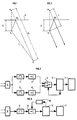
- the device for implementing the method comprises, for each of the sources, a single sensor H placed nearby and connected to the input of an acquisition system shown in FIG. 3.
- the signal supplied by the sensor H is applied to the input of two different amplification channels, each comprising a bandpass filter 1, 2 and an amplifier 3, 4.
- the two amplifiers 3, 4 have different gains g 1 and g 2 .
- the signals which they deliver are applied to two inputs of an electronic switch 5, the output of this being connected to the input of a digitization and recording assembly 6.
- This comprises means for memorizing the different emission signatures constituting the catalog and means for delivering a control signal from the switch 5, making it possible to select one or the other of the signals coming from the amplifiers 3 or 4.
- a computer 7 is connected to the digitization and recording assembly 6. It is suitable for carrying out the combinations of emission signatures selected from the catalog to synthesize the global signature ad infinitum of all the sources.
- the gain of the amplifier 3 is chosen to be large enough so that the signal which it delivers constitutes an accurate measurement of the hydro static pressure and consequently of the depth of immersion of the associated source.
- amplifier 4 is chosen lower so that the signal at its output faithfully and without clipping restores the variations in pressure generated by the source when it is triggered.
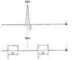
- a source having to be triggered at an instant t (Fig. 5), a measurement is made of the depth of immersion at an anterior instant t i and at a posterior instant t 2 (Fig. 6).
- the assembly 6 applies to the switch 5 at times t 1 and t 2 and during a time interval or window AT, a control signal making it possible to select the amplifier 3.
- the two depth measurements which frame the triggering instant t are successively memorized and the computer 7 interpolates between them, so as to precisely determine the depth of immersion of the source at the time of the "firing". Outside these two depth measurement windows, the switch is controlled to select the signal delivered by the amplifier 4 which translates the emission signature of the source.
- the acquisition system can comprise a single amplification channel comprising a band-pass filter 8 and a variable gain amplifier 9 whose gain can take at least two gain values different g 1 , g 2 according to the control signal applied to it by a gain control element 10 controlled by the recording assembly 6.
- the gain g i allowing a fine measurement of the immersion depth is applied to the amplifier 9 at instants t 1 and t 2 and during a time interval eT.
- the gain g 2 is applied outside of the measurement windows, so as to obtain the emission signature of the source.
- the computer 7 determines the precise value of the immersion depth by interpolations between the values measured at times t 1 and t 2 .
Description
L'invention a pour objet un procédé de détermination de la signature à grande distance d'un ensemble d'émission d'impulsions sismiques dans l'eau, comportant une pluralité de sources sismiques combinées et en particulier d'un ensemble de sources sismiques fonctionnant par implosion, et un dispositif pour sa mise en oeuvre.The subject of the invention is a method for determining the long-distance signature of a set of emission of seismic pulses in water, comprising a plurality of combined seismic sources and in particular of a set of seismic sources operating by implosion, and a device for its implementation.
L'émission dans l'eau d'impulsions sismiques peut être obtenue par exemple par la brusque contraction d'une cavité immergée où règne une pression très faible par rapport à la pression hydrostatique. Cette cavité peut être délimitée par les parois d'une enceinte de volume variable du type décrit par exemple dans le brevet français FR-A 1.583.737.The emission into the water of seismic pulses can be obtained for example by the sudden contraction of an immersed cavity where there is a very low pressure compared to the hydrostatic pressure. This cavity can be delimited by the walls of an enclosure of variable volume of the type described for example in French patent FR-A 1,583,737.
Elle peut être obtenue également par la décharge à grande vitesse dans l'eau d'un certain volume de liquide sous pression contenu dans une chambre immergée. Une source du type canon à eau est décrite par exemple dans le brevet français FR-A 2 558 600.It can also be obtained by discharging at high speed into water a certain volume of pressurized liquid contained in an immersed chamber. A source of the water cannon type is described for example in French patent FR-A 2,558,600.
Les impulsions sismiques engendrées ont une forme qui dépend du type de source utilisé, de ses caractéristiques mécaniques, éventuellement de la pression du fluide hydraulique propulseur permettant l'éjection de liquide, et aussi de sa profondeur d'immersion.The seismic pulses generated have a shape which depends on the type of source used, on its mechanical characteristics, possibly on the pressure of the propellant hydraulic fluid allowing the ejection of liquid, and also on its depth of immersion.
La forme des impulsions sismiques engendrées par une source déterminée, qui constitue la signature d'émission de celle-ci, est en général bien reproductible dans des conditions définies d'utilisation et ne dépend que de la profondeur d'immersion. On la détermine au moyen d'un capteur de pression disposé à proximité.The shape of the seismic pulses generated by a determined source, which constitutes the emission signature of the latter, is generally well reproducible under defined conditions of use and depends only on the depth of immersion. It is determined by means of a pressure sensor located nearby.
Lorsque plusieurs sources sont actionnées en combinaison, elles interagissent les unes sur les autres de manière complexe si bien que la signature de chacune d'elles, mesurée par un capteur de pression proche, est différente de celle que l'on obtient lorsqu'elle fonctionne isolément.When several sources are actuated in combination, they interact with each other in a complex way so that the signature of each of them, measured by a nearby pressure sensor, is different from that obtained when it is operating isolation.
Pour certains traitements des enregistrements obtenus en captant les échos sur les différentes couches réfléchissantes du sous-sol, il est important de connaître la signature globale à l'infini de l'ensemble des sources combinées. Une telle signature peut être obtenue par une combinaison linéaire des signatures des différentes sources considérées isolément. Ceci est impossible à faire directement à partir des mesures effectuées par différents capteurs de pression immergés au voisinage des différentes sources du fait des interactions qui se produisent.For certain processing of the recordings obtained by capturing the echoes on the different reflective layers of the basement, it is important to know the global signature at infinity of all the combined sources. Such a signature can be obtained by a linear combination of the signatures of the different sources considered in isolation. This is impossible to do directly from the measurements made by different pressure sensors immersed in the vicinity of the different sources due to the interactions that occur.
Un procédé connu pour déterminer la signature globale d'un ensemble de sources combinées consiste à immerger autant de capteurs de pression qu'il y a de sources, la position des capteurs relativement à celles-ci étant connue, à traiter leurs différentes mesures en tenant compte des interactions de manière à déterminer les signatures équivalentes des sources, corrigées des effets d'interaction, et à superposer les signatures corrigées pour obtenir la signature globale à grande distance.A known method for determining the global signature of a set of combined sources consists in immersing as many pressure sensors as there are sources, the position of the sensors relative to these being known, in processing their different measurements taking account for interactions so as to determine the equivalent signatures of the sources, corrected for interaction effects, and to superimpose the corrected signatures to obtain the global signature over a long distance.
Une telle méthode qui est appliquée à des canons à air et décrite dans la demande de brevet européen EP-A 66.423, est difficile à mettre en pratique car elle exige une connaissance précise de la position des différents capteurs et des différentes sources relativement les uns aux autres aux instants de déclenchement, et ceci est d'autant plus difficile à réaliser que le nombre d'éléments du dispositif d'émission est important.Such a method which is applied to air cannons and described in European patent application EP-A 66,423, is difficult to put into practice because it requires precise knowledge of the position of the different sensors and of the different sources relatively to each other. others at the instants of triggering, and this is all the more difficult to achieve when the number of elements of the transmitting device is large.
Le procédé selon l'invention permet de déterminer la signature d'émission globale à grande distance d'un ensemble d'émission comportant un nombre N de sources combinées, qui n'a pas les inconvénients indiqués ci-dessus.The method according to the invention makes it possible to determine the global long distance transmission signature of a transmission assembly comprising a number N of combined sources, which does not have the drawbacks indicated above.
Il est caractérisé en ce qu'il comporte :
- - la mesure des signatures d'émission de chacune des N sources actionnée isolément, préalablement à l'utilisation de l'ensemble d'émission, pour différentes valeurs de paramètres influant sur la forme des impulsions produites par les sources, au moyen de capteurs appropriés disposés au voisinage de chacune des N sources et l'établissement d'un catalogue de toutes les mesures effectuées successivement pour toutes les sources de l'ensemble d'émission,
- - la mesure des valeurs effectives de ces mêmes paramètres pour toutes les sources, au moment de leur utilisation combinée,
- - la sélection dans le catalogue des signatures respectives des N sources de l'ensemble d'émission correspondant aux valeurs effectives mesurées pour lesdits paramètres, et
- - la détermination de la signature d'émission globale à grande distance de l'ensemble d'émission par une combinaison linéaire des N signatures d'émission sélectionnées dans le catalogue, en tenant compte des instants de déclenchement effectifs des différentes sources de l'ensemble d'émission.
- - the measurement of the emission signatures of each of the N sources activated in isolation, prior to the use of the emission assembly, for different values of parameters influencing the shape of the pulses produced by the sources, by means of appropriate sensors arranged in the vicinity of each of the N sources and the establishment of a catalog of all the measurements carried out successively for all the sources of the emission assembly,
- - the measurement of the effective values of these same parameters for all sources, at the time of their combined use,
- the selection from the catalog of the respective signatures of the N sources of the transmission assembly corresponding to the actual values measured for said parameters, and
- - the determination of the global long distance emission signature of the emission assembly by a linear combination of the N emission signatures selected in the catalog, taking into account the effective triggering times of the different sources of the assembly resignation.
La constitution préalable d'un catalogue de signatures des différentes sources fonctionnant chacune de manière isolée, et par conséquent exemptes des perturbations apportées par leur utilisation combinée, et la mesure des paramètres de fonctionnement de chaque source permettant de sélectionner la signature d'émission cataloguée qu'elle aurait dans ces mêmes conditions de fonctionnement si elle émettait toute seule, rend possible par synthèse, la détermination de la signature globale à grande distance de l'ensemble d'émission, et ceci sans avoir à connaître la configuration relative des sources et des capteurs de mesure.The prior constitution of a signature catalog of the different sources each operating in isolation, and therefore free from the disturbances brought about by their combined use, and the measurement of the operating parameters of each source making it possible to select the emission signature cataloged that '' it would have under these same operating conditions if it emitted all alone, makes possible by synthesis, the determination of the global signature at long distance of the emission assembly, and this without having to know the relative configuration of the sources and measurement sensors.
Les paramètres influant sur la forme des impulsions produites sont la profondeur et éventuellement d'autres paramètres dépendant du type de source utilisée.The parameters influencing the shape of the pulses produced are the depth and possibly other parameters depending on the type of source used.
D'autres caractéristiques et avantages du procédé selon l'invention et de son dispositif de mise en oeuvre, apparaîtront à la lecture de la description de modes de réalisation particuliers, donnés à titre d'exemples non limitatifs et illustrés par les dessins annexés, où :
- - la figure 1 représente schématiquement les trajets des ondes acoustiques entre un emplacement de source ei au voisinage de la surface de l'eau I et celui d'un capteur H disposé à une certaine distance de la source,
- - la figure 2 est analogue à la figure 1 et correspond au cas où le capteur est reporté à l'infini,
- - la figure 3 représente le schéma synoptique d'un premier mode de réalisation du dispositif de mise en oeuvre,
- - la figure 4 représente le schéma synoptique d'une variante du mode de réalisation de la figure 3,
- - la figure 5 représente très schématiquement une signature de source, et,
- - la figure 6 représente un chronogramme d'un signal de commande permettant d'utiliser un capteur à la fois pour mesurer la profondeur d'immersion d'une source et de déterminer sa signature d'émission.
- FIG. 1 schematically represents the paths of the acoustic waves between a source location ei in the vicinity of the surface of the water I and that of a sensor H placed at a certain distance from the source,
- FIG. 2 is similar to FIG. 1 and corresponds to the case where the sensor is carried over to infinity,
- FIG. 3 represents the block diagram of a first embodiment of the implementation device,
- FIG. 4 represents the block diagram of a variant of the embodiment of FIG. 3,
- FIG. 5 very schematically represents a source signature, and,
- - Figure 6 shows a timing diagram of a control signal making it possible to use one sensor at a time to measure the immersion depth of a source and to determine its emission signature.
La signature d'une source ei est la variation en fonction du temps t de la pression mesurée par le capteur H résultant de l'impulsion acoustique émise par la source après son déclenchement (Fig. 1).The signature of a source e i is the variation as a function of time t of the pressure measured by the sensor H resulting from the acoustic pulse emitted by the source after its triggering (Fig. 1).
La signature rapprochée si (ou "near field") est mesurée à une distance de référence ri de l'ordre de 1 mètre par exemple. La signature de la source, mesurée à une certaine distance au-dessous de la source, est une combinaison de l'impulsion qui se propage directement de ei à H avec celle, désignée généralement par "fantôme" qui parvient au capteur décalé dans le temps après réflexion en un point Mi sur l'interface eau/air 1.The close signature if (or "near field") is measured at a reference distance ri of the order of 1 meter for example. The signature of the source, measured at a certain distance below the source, is a combination of the pulse which propagates directly from ei to H with that, generally designated by "phantom" which reaches the sensor shifted in time after reflection at a point M i on the water /
Lorsque l'on utilise plusieurs sources ei disposées à des profondeurs di, on les déclenche de manière à mettre en phase leurs pics d'implosion respectifs. Le décalage de temps entre les instants de déclenchement de deux sources quelconques correspondant à la durée de propagation des ondes acoustiques de l'une à l'autre, à la vitesse de propagation V.When using several sources e i arranged at depths di, they are triggered so as to phase their respective implosion peaks. The time difference between the instants of triggering of any two sources corresponding to the duration of propagation of the acoustic waves from one to the other, at the propagation speed V.
La signature éloignée SH (ou "far field") d'un ensemble de N sources ei, mesurée par l'hydrophone H s'exprime de manière connue par la relation :
On peut montrer, et cela est bien connu des spécialistes, que la signature S à l'infini ou pour le moins à très grande distance (Fig. 2), d'un ensemble d'émission constitué d'un nombre N de sources à implosion, ei, e2...eN déclenchées en séquence de manière à mettre en phase leurs pics d'implosion, est une combinaison linéaire des signatures si des différentes sources e; considérées isolément et s'exprime par une relation du type :
Le procédé selon l'invention comporte la mesure préalable des signatures d'émission de chacune des sources ei actionnée isolément par un hydrophone disposé à courte distance (1 mètre par exemple) pour différentes valeurs de paramètres influant sur la forme des impulsions produites. Le principal paramètre est la profondeur d'immersion.The method according to the invention comprises the prior measurement of the emission signatures of each of the sources ei actuated in isolation by a hydrophone placed at a short distance (1 meter for example) for different values of parameters influencing the shape of the pulses produced. The main parameter is the depth of immersion.
D'autres paramètres, tenant plus spécifiquement à la nature des sources, tels que la pression du fluide éjecté dans le cas de canons à implosion, sont également pris en compte.Other parameters, more specifically related to the nature of the sources, such as the pressure of the fluid ejected in the case of imploding guns, are also taken into account.
On corrige de préférence les signatures d'émission mesurées, de manière à éliminer de celles-ci les contributions dues aux réflexions sur l'interface eau/air 1 ("fantômes"). Les mesures étant faites à proximité immédiate de chaque source ei, l'intensité relative des "fantômes" par rapport à celles des impulsions directes, est relativement faible (de l'ordre de 1/10e).The measured emission signatures are preferably corrected so as to eliminate from them the contributions due to reflections on the water / air interface 1 ("ghosts"). The measurements being made in the immediate vicinity of each source ei, the relative intensity of the "ghosts" compared to those of the direct pulses, is relatively low (of the order of 1/10 e ).
On dresse alors un catalogue de toutes les mesures effectuées successivement pour toutes les sources. Les données de ce catalogue sont stockées par exemple dans une mémoire de calculateur.We then draw up a catalog of all the measurements carried out successively for all the sources. The data in this catalog is stored, for example, in a computer memory.
Lorsque l'ensemble d'émission est remorqué dans l'eau dans le cadre d'opérations de prospection sismique en mer, et que ses différentes sources sont actionnées, on procède de la manière suivante :
- - On mesure au moyen d'hydrophones disposés à proximité immédiate de chacune d'elles, leurs profondeurs d'immersion respectives. On mesure éventuellement au moyen d'autres capteurs appropriés les valeurs d'autres paramètres influant sur leurs signatures.
- - On enregistre les signatures d'émission des différentes sources, de manière à déterminer les instants respectifs de leurs pics d'implosion et aussi à détecter d'éventuelles anomalies ou perturbations de fonctionnement.
- - On modifie chacune des signatures d'émission extraites du catalogue, de manière à lui ajouter la contribution due aux réflexions sur l'interface, que l'on observerait à très grande distance à la profondeur effective d'utilisation de la source correspondante. La contribution du "fantôme" à la signature d'émission de la source est, à l'infini, pratiquement identique à celle de l'onde directe, du point de vue amplitude. La modification consiste essentiellement à ajouter à chaque signature d'émission celle d'un "fantôme" d'amplitude égale convenablement déphasé.
- - On effectue alors une combinaison linéaire des signatures modifiées en accord avec la relation 2. De préférence, on déphase les signatures modifiées avant leur combinaison, de manière à tenir compte des intervalles de temps entre les instants de déclenchement respectifs des différentes sources, qu'ils soient introduits délibérément ou résultent d'une certaine dispersion dans les conditions de fonctionnement.
- - Their respective immersion depths are measured by means of hydrophones placed in the immediate vicinity of each of them. The values of other parameters influencing their signatures may be measured by means of other appropriate sensors.
- - The emission signatures of the different sources are recorded, so as to determine the respective instants of their implosion peaks and also to detect any anomalies or disturbances in operation.
- - Each of the emission signatures extracted from the catalog is modified, so as to add to it the contribution due to reflections on the interface, which would be observed at very great distance from the effective depth of use of the corresponding source. The contribution of the "phantom" to the emission signature of the source is, at infinity, practically identical to that of the direct wave, from the amplitude point of view. The modification essentially consists in adding to each emission signature that of a "ghost" of equal amplitude suitably out of phase.
- - We then perform a linear combination of the modified signatures in accordance with relation 2. Preferably, we phase out the modified signatures before their combination, so as to take account of the time intervals between the respective triggering instants of the different sources, that they are introduced deliberately or result from a certain dispersion in the operating conditions.
On peut alors utiliser la signature à l'infini que l'on a synthétisée par cette combinaison pour différentes opérations de traitement sur les enregistrements sismiques réalisés à partir des échos sur des réflecteurs souterrains, des ébranlements sismiques engendrés par l'ensemble de sources.We can then use the infinite signature that we synthesized by this combination for different processing operations on the seismic recordings made from echoes on underground reflectors, seismic shocks generated by the set of sources.
Les deux étapes de correction ou modification des signatures avant leur inclusion dans le catalogue pour éliminer la contribution du fantôme à l'infini, sont facultatives. Elles peuvent être aussi réalisées toutes les deux au moment de la constitution du catalogue, de manière à collecter dans celui-ci des exemplaires de signatures à l'infini prêtes pour les combinaisons.The two stages of correction or modification of signatures before their inclusion in the catalog to eliminate the contribution of the ghost to infinity, are optional. They can also be carried out both at the time of the constitution of the catalog, so as to collect in it copies of infinite signatures ready for combinations.
La mise en oeuvre du procédé est effectuée avantageusement en utilisant des moyens de réception adaptés à mesurer alternativement la profondeur d'immersion de chaque source et sa signature d'émission, la profondeur d'immersion au moment précis de son déclenchement étant déterminée par combinaison des mesures de profondeur antérieures et postérieures à l'instant de "tir".The implementation of the method is advantageously carried out using reception means suitable for alternately measuring the immersion depth of each source and its emission signature, the immersion depth at the precise moment of its triggering being determined by combination of the depth measurements before and after the moment of "firing".
Le dispositif de mise en oeuvre du procédé comporte pour chacune des sources un capteur unique H disposé à proximité et connecté à l'entrée d'un système d'acquisition représenté à la figure 3. Le signal fourni par le capteur H est appliqué à l'entrée de deux voies d'amplification différentes, chacune comportant un filtre passe-bande 1, 2 et un amplificateur 3, 4.The device for implementing the method comprises, for each of the sources, a single sensor H placed nearby and connected to the input of an acquisition system shown in FIG. 3. The signal supplied by the sensor H is applied to the input of two different amplification channels, each comprising a
Les deux amplificateurs 3, 4 ont des gains différents g1 et g2. Les signaux qu'ils délivrent sont appliqués à deux entrées d'un commutateur électronique 5, la sortie de celui-ci étant connectée à l'entrée d'un ensemble de numérisation et d'enregistrement 6. Celui-ci comporte des moyens pour mémoriser les différentes signatures d'émission constituant le catalogue et des moyens pour délivrer un signal de commande du commutateur 5, permettant de sélectionner l'un ou l'autre des signaux issus des amplificateurs 3 ou 4.The two amplifiers 3, 4 have different gains g 1 and g 2 . The signals which they deliver are applied to two inputs of an
Un calculateur 7 est connecté à l'ensemble de numérisation et d'enregistrement 6. Il est adapté à effectuer les combinaisons de signatures d'émission sélectionnées dans le catalogue pour synthétiser la signature globale à l'infini de l'ensemble des sources.A computer 7 is connected to the digitization and
Le gain de l'amplificateur 3 est choisi suffisamment grand pour que le signal qu'il délivre constitue une mesure précise de la pression hydro statique et par conséquent, de la profondeur d'immersion de la source associée.The gain of the amplifier 3 is chosen to be large enough so that the signal which it delivers constitutes an accurate measurement of the hydro static pressure and consequently of the depth of immersion of the associated source.
Celui de l'amplificateur 4 est choisi plus faible pour que le signal à sa sortie restitue fidèlement et sans écrêtage, les variations de la pression engendrées par la source à son déclenchement.That of amplifier 4 is chosen lower so that the signal at its output faithfully and without clipping restores the variations in pressure generated by the source when it is triggered.
Une source devant être déclenchée à un instant t (Fig. 5), on effectue une mesure de la profondeur d'immersion à un instant ti antérieur et à un instant t2 postérieur (Fig. 6). A cet effet, l'ensemble 6 applique au commutateur 5 aux instants t1 et t2 et pendant un intervalle de temps ou fenêtre AT, un signal de commande permettant de sélectionner l'amplificateur 3.A source having to be triggered at an instant t (Fig. 5), a measurement is made of the depth of immersion at an anterior instant t i and at a posterior instant t 2 (Fig. 6). To this end, the
Les deux mesures de profondeur qui encadrent l'instant t de déclenchement sont successivement mémorisées et le calculateur 7 effectue une interpolation entre elles, de manière à déterminer avec précision la profondeur d'immersion de la source au moment du "tir". En dehors de ces deux fenêtres de mesure de profondeur, le commutateur est commandé pour sélectionner le signal délivré par l'amplificateur 4 qui traduit la signature d'émission de la source.The two depth measurements which frame the triggering instant t are successively memorized and the computer 7 interpolates between them, so as to precisely determine the depth of immersion of the source at the time of the "firing". Outside these two depth measurement windows, the switch is controlled to select the signal delivered by the amplifier 4 which translates the emission signature of the source.
Suivant un autre mode de réalisation (Fig. 4), le système d'acquisition peut comporter une voie unique d'amplification comportant un filtre passe-bande 8 et un amplificateur à gain variable 9 dont le gain peut prendre au moins deux valeurs de gain différentes g1, g2 suivant le signal de commande que lui applique un élément de contrôle de gain 10 piloté par l'ensemble d'enregistrement 6. Le gain gi permettant une mesure fine de la profondeur d'immersion est appliquée à l'amplificateur 9 aux instants t1 et t2 et pendant un intervalle de temps eT.According to another embodiment (Fig. 4), the acquisition system can comprise a single amplification channel comprising a band-pass filter 8 and a
Le gain g2 lui, est appliqué en dehors des fenêtres de mesure, de façon à obtenir la signature d'émission de la source. De la même manière, le calculateur 7 détermine la valeur précise de la profondeur d'immersion par interpolations entre les valeurs mesurées aux instants t1 et t2.The gain g 2 is applied outside of the measurement windows, so as to obtain the emission signature of the source. In the same way, the computer 7 determines the precise value of the immersion depth by interpolations between the values measured at times t 1 and t 2 .
Claims (7)
Applications Claiming Priority (2)
| Application Number | Priority Date | Filing Date | Title |
|---|---|---|---|
| FR8507582A FR2582107B1 (en) | 1985-05-17 | 1985-05-17 | METHOD AND DEVICE FOR DETERMINING THE SIGNATURE OF A LONG DISTANCE TRANSMISSION OF A SEISMIC TRANSMISSION ASSEMBLY |
| FR8507582 | 1985-05-17 |
Publications (2)
| Publication Number | Publication Date |
|---|---|
| EP0204599A1 EP0204599A1 (en) | 1986-12-10 |
| EP0204599B1 true EP0204599B1 (en) | 1989-11-02 |
Family
ID=9319412
Family Applications (1)
| Application Number | Title | Priority Date | Filing Date |
|---|---|---|---|
| EP86401013A Expired EP0204599B1 (en) | 1985-05-17 | 1986-05-12 | Process and device for determining from a great distance the signature of a group of seismic emitters |
Country Status (12)
| Country | Link |
|---|---|
| US (1) | US4827456A (en) |
| EP (1) | EP0204599B1 (en) |
| JP (1) | JPH0616113B2 (en) |
| AU (1) | AU586681B2 (en) |
| CA (1) | CA1270937A (en) |
| DE (1) | DE3666740D1 (en) |
| DK (1) | DK231786A (en) |
| ES (1) | ES8801442A1 (en) |
| FR (1) | FR2582107B1 (en) |
| GR (1) | GR861172B (en) |
| NO (1) | NO168206C (en) |
| PT (1) | PT82597B (en) |
Families Citing this family (6)
| Publication number | Priority date | Publication date | Assignee | Title |
|---|---|---|---|---|
| US4908801A (en) * | 1989-05-30 | 1990-03-13 | Teledyne Exploration | Real-time simulation of the far-field signature of a seismic sound source array |
| FR2687227B1 (en) * | 1992-02-06 | 1994-05-20 | Geophysique Cie Generale | METHOD FOR DETERMINING A FAR FIELD SIGNATURE OF A PLURALITY OF SEISMIC SOURCES. |
| GB2433594B (en) * | 2005-12-23 | 2008-08-13 | Westerngeco Seismic Holdings | Methods and systems for determining signatures for arrays of marine seismic sources for seismic analysis |
| US10228479B2 (en) | 2016-02-26 | 2019-03-12 | Ion Geophysical Corporation | Dynamic gain adjustments in seismic surveys |
| AU2017233533B2 (en) | 2016-03-16 | 2020-01-02 | Exxonmobil Upstream Research Company | Method to estimate and remove direct arrivals from arrayed marine sources |
| US10768325B2 (en) | 2016-10-27 | 2020-09-08 | Exxonmobil Upstream Research Company | Method to estimate 4D seismic acquisition repeatability specifications from high-resolution near-water-bottom seismic images |
Family Cites Families (12)
| Publication number | Priority date | Publication date | Assignee | Title |
|---|---|---|---|---|
| US3398394A (en) * | 1966-12-09 | 1968-08-20 | Teledyne Ind | Marine seismic array depth control |
| US3786408A (en) | 1972-01-03 | 1974-01-15 | Texaco Inc | Method and apparatus for offshore geophysical exploration with low power seismic source |
| US3866161A (en) * | 1973-01-24 | 1975-02-11 | Petty Ray Geophysical Inc | Method and apparatus for obtaining a more accurate measure of input seismic energy |
| US3919685A (en) * | 1973-11-26 | 1975-11-11 | Geo Space Corp | Seismic data acquisition system and method |
| US4500978A (en) * | 1980-04-23 | 1985-02-19 | Seismograph Service Corporation | Seismographic method and apparatus using scaled sound sources |
| DE3171812D1 (en) * | 1980-08-29 | 1985-09-19 | British National Oil Corp | Improvements in or relating to determination of far field signatures, for instance of seismic sources |
| US4486864A (en) * | 1980-09-08 | 1984-12-04 | Shell Oil Company | Method for marine seismic exploration |
| ATE31978T1 (en) * | 1981-05-29 | 1988-01-15 | Britoil Plc | METHOD FOR DETERMINING THE WAVEFORMS TRANSMITTED BY AN ARRANGEMENT OF UNDERWATER SEISMIC SOURCES AND FOR DATA ACCUMULATION FOR APPLICATION IN THIS PROCEDURE. |
| GB2134257B (en) * | 1983-01-19 | 1986-03-12 | Shell Int Research | Signal improvement in marine seismic exploration |
| US4648080A (en) * | 1984-06-15 | 1987-03-03 | Western Geophysical Company | Method for determining the far field signature of a marine seismic source from near-field measurements |
| US4599892A (en) * | 1984-12-04 | 1986-07-15 | Doshi Navin H | Volume measuring apparatus |
| US4704902A (en) * | 1984-12-04 | 1987-11-10 | Doshi Navin H | Acoustical volume/pressure measurement device |
-
1985
- 1985-05-17 FR FR8507582A patent/FR2582107B1/en not_active Expired
-
1986
- 1986-04-30 GR GR861172A patent/GR861172B/en unknown
- 1986-05-12 EP EP86401013A patent/EP0204599B1/en not_active Expired
- 1986-05-12 DE DE8686401013T patent/DE3666740D1/en not_active Expired
- 1986-05-14 ES ES554980A patent/ES8801442A1/en not_active Expired
- 1986-05-15 NO NO861941A patent/NO168206C/en unknown
- 1986-05-16 US US06/863,795 patent/US4827456A/en not_active Expired - Fee Related
- 1986-05-16 CA CA000509402A patent/CA1270937A/en not_active Expired - Fee Related
- 1986-05-16 JP JP61110970A patent/JPH0616113B2/en not_active Expired - Lifetime
- 1986-05-16 DK DK231786A patent/DK231786A/en not_active Application Discontinuation
- 1986-05-16 PT PT82597A patent/PT82597B/en not_active IP Right Cessation
- 1986-05-16 AU AU57495/86A patent/AU586681B2/en not_active Ceased
Also Published As
| Publication number | Publication date |
|---|---|
| GR861172B (en) | 1986-09-01 |
| FR2582107B1 (en) | 1988-07-15 |
| DE3666740D1 (en) | 1989-12-07 |
| AU586681B2 (en) | 1989-07-20 |
| PT82597A (en) | 1986-06-01 |
| ES8801442A1 (en) | 1987-12-16 |
| NO168206B (en) | 1991-10-14 |
| EP0204599A1 (en) | 1986-12-10 |
| FR2582107A1 (en) | 1986-11-21 |
| ES554980A0 (en) | 1987-12-16 |
| NO168206C (en) | 1992-01-22 |
| AU5749586A (en) | 1986-11-20 |
| JPH0616113B2 (en) | 1994-03-02 |
| PT82597B (en) | 1994-11-30 |
| DK231786D0 (en) | 1986-05-16 |
| JPS61270690A (en) | 1986-11-29 |
| CA1270937A (en) | 1990-06-26 |
| US4827456A (en) | 1989-05-02 |
| NO861941L (en) | 1986-11-18 |
| DK231786A (en) | 1986-11-18 |
Similar Documents
| Publication | Publication Date | Title |
|---|---|---|
| FR2664063A1 (en) | Method and device for optimising the triggering of a set of marine seismic sources | |
| EP0541434B1 (en) | Method and apparatus for the ultrasonic testing of workpieces | |
| CA2292257C (en) | Method and system for synchronized acquisition of seismic signals | |
| EP0313459B1 (en) | Process and device for seismic data acquisition | |
| EP0271537B1 (en) | Method for determining the geometry of a multisource seismic wave emission device | |
| EP0904535B1 (en) | Method and device for detecting and locating a reverberating source of sound | |
| EP0215703B1 (en) | System for measuring the acoustical reflection coefficient of underwater reflectors | |
| FR2885414A1 (en) | SOURCE SIGNATURE DECONVOLUTION METHOD | |
| FR2782389A1 (en) | METHOD AND DEVICE FOR CORRECTING THE EFFECTS OF SHIP DISPLACEMENT IN SEISMIC MARITIME MEASUREMENTS | |
| FR2874270A1 (en) | SEISMIC EXPLORATION METHOD | |
| FR2876458A1 (en) | IMPROVEMENT TO SEISMIC TREATMENTS FOR THE SUPPRESSION OF MULTIPLE REFLECTIONS | |
| FR2628216A1 (en) | ULTRASONIC ANEMOMETER | |
| FR2737309A1 (en) | METHOD OF REDUCING NOISE IN SEISMIC SIGNALS BY ADAPTIVE FILTERING OF A NOISE REFERENCE | |
| EP0555148B1 (en) | Process for determining the far-field signature of a plurality of seismic sources | |
| GB2125550A (en) | Underwater seismic testing | |
| CA2234465C (en) | Procedure and device for processing signals representative of waves reflected, transmitted or refracted by a 3-dimensional structure in order to explore and analyse the structure | |
| FR2779532A1 (en) | METHOD FOR MITIGATION OF WATER COLUMN REVERBERATIONS IN A SEISMIC SIGNAL OF DUAL SENSORS | |
| EP0204599B1 (en) | Process and device for determining from a great distance the signature of a group of seismic emitters | |
| FR2795181A1 (en) | Three-dimensional seismic prospecting technique for subsea locations, comprises generation of additional lines of data from data produced by lines of receptors | |
| FR2664064A1 (en) | Method and device for monitoring a submerged multisource assembly for emitting acoustic pulses | |
| EP0515652B1 (en) | Method and device for measuring the rate of penetration of equipment in a well | |
| FR2799552A1 (en) | Data handling for acoustic array where data is treated for sub-groups of receivers before being combined for final result | |
| FR2858062A1 (en) | Sound propagation time measuring apparatus for measuring objects distance, has calculation device calculating sound propagation time and time difference of sound reception signal based on pulsed signal produced by inverse analysis device | |
| EP0718638A1 (en) | Method of detection of objects located in a ground area or of determination of the propagation characteristics of an acoustic wave in the ground, and system to carry out these methods | |
| FR2752461A1 (en) | METHOD AND DEVICE FOR PROCESSING SIGNALS REPRESENTATIVE OF WAVES REFLECTED OR TRANSMITTED BY A VOLUME STRUCTURE WITH A VIEW TO PERFORMING AN EXPLORATION AND ANALYSIS OF THIS STRUCTURE |
Legal Events
| Date | Code | Title | Description |
|---|---|---|---|
| PUAI | Public reference made under article 153(3) epc to a published international application that has entered the european phase |
Free format text: ORIGINAL CODE: 0009012 |
|
| AK | Designated contracting states |
Kind code of ref document: A1 Designated state(s): DE GB IT NL |
|
| 17P | Request for examination filed |
Effective date: 19870318 |
|
| 17Q | First examination report despatched |
Effective date: 19880810 |
|
| ITF | It: translation for a ep patent filed |
Owner name: DE DOMINICIS & MAYER S.R.L. |
|
| GRAA | (expected) grant |
Free format text: ORIGINAL CODE: 0009210 |
|
| AK | Designated contracting states |
Kind code of ref document: B1 Designated state(s): DE GB IT NL |
|
| GBT | Gb: translation of ep patent filed (gb section 77(6)(a)/1977) | ||
| REF | Corresponds to: |
Ref document number: 3666740 Country of ref document: DE Date of ref document: 19891207 |
|
| PLBE | No opposition filed within time limit |
Free format text: ORIGINAL CODE: 0009261 |
|
| STAA | Information on the status of an ep patent application or granted ep patent |
Free format text: STATUS: NO OPPOSITION FILED WITHIN TIME LIMIT |
|
| 26N | No opposition filed | ||
| ITTA | It: last paid annual fee | ||
| PGFP | Annual fee paid to national office [announced via postgrant information from national office to epo] |
Ref country code: GB Payment date: 19930422 Year of fee payment: 8 |
|
| PGFP | Annual fee paid to national office [announced via postgrant information from national office to epo] |
Ref country code: NL Payment date: 19930531 Year of fee payment: 8 |
|
| PGFP | Annual fee paid to national office [announced via postgrant information from national office to epo] |
Ref country code: DE Payment date: 19930618 Year of fee payment: 8 |
|
| PG25 | Lapsed in a contracting state [announced via postgrant information from national office to epo] |
Ref country code: GB Effective date: 19940512 |
|
| PG25 | Lapsed in a contracting state [announced via postgrant information from national office to epo] |
Ref country code: NL Effective date: 19941201 |
|
| GBPC | Gb: european patent ceased through non-payment of renewal fee |
Effective date: 19940512 |
|
| NLV4 | Nl: lapsed or anulled due to non-payment of the annual fee | ||
| PG25 | Lapsed in a contracting state [announced via postgrant information from national office to epo] |
Ref country code: DE Effective date: 19950201 |
|
| PG25 | Lapsed in a contracting state [announced via postgrant information from national office to epo] |
Ref country code: IT Free format text: LAPSE BECAUSE OF NON-PAYMENT OF DUE FEES;WARNING: LAPSES OF ITALIAN PATENTS WITH EFFECTIVE DATE BEFORE 2007 MAY HAVE OCCURRED AT ANY TIME BEFORE 2007. THE CORRECT EFFECTIVE DATE MAY BE DIFFERENT FROM THE ONE RECORDED. Effective date: 20050512 |