EP0204503B1 - Hochdruckgaspatrone - Google Patents
Hochdruckgaspatrone Download PDFInfo
- Publication number
- EP0204503B1 EP0204503B1 EP19860304055 EP86304055A EP0204503B1 EP 0204503 B1 EP0204503 B1 EP 0204503B1 EP 19860304055 EP19860304055 EP 19860304055 EP 86304055 A EP86304055 A EP 86304055A EP 0204503 B1 EP0204503 B1 EP 0204503B1
- Authority
- EP
- European Patent Office
- Prior art keywords
- sealing plate
- gas
- regulator
- high pressure
- cartridge
- Prior art date
- Legal status (The legal status is an assumption and is not a legal conclusion. Google has not performed a legal analysis and makes no representation as to the accuracy of the status listed.)
- Expired
Links
Images

Classifications
-
- F—MECHANICAL ENGINEERING; LIGHTING; HEATING; WEAPONS; BLASTING
- F17—STORING OR DISTRIBUTING GASES OR LIQUIDS
- F17C—VESSELS FOR CONTAINING OR STORING COMPRESSED, LIQUEFIED OR SOLIDIFIED GASES; FIXED-CAPACITY GAS-HOLDERS; FILLING VESSELS WITH, OR DISCHARGING FROM VESSELS, COMPRESSED, LIQUEFIED, OR SOLIDIFIED GASES
- F17C13/00—Details of vessels or of the filling or discharging of vessels
- F17C13/12—Arrangements or mounting of devices for preventing or minimising the effect of explosion ; Other safety measures
- F17C13/123—Arrangements or mounting of devices for preventing or minimising the effect of explosion ; Other safety measures for gas bottles, cylinders or reservoirs for tank vehicles or for railway tank wagons
-
- F—MECHANICAL ENGINEERING; LIGHTING; HEATING; WEAPONS; BLASTING
- F17—STORING OR DISTRIBUTING GASES OR LIQUIDS
- F17C—VESSELS FOR CONTAINING OR STORING COMPRESSED, LIQUEFIED OR SOLIDIFIED GASES; FIXED-CAPACITY GAS-HOLDERS; FILLING VESSELS WITH, OR DISCHARGING FROM VESSELS, COMPRESSED, LIQUEFIED, OR SOLIDIFIED GASES
- F17C13/00—Details of vessels or of the filling or discharging of vessels
- F17C13/06—Closures, e.g. cap, breakable member
-
- F—MECHANICAL ENGINEERING; LIGHTING; HEATING; WEAPONS; BLASTING
- F17—STORING OR DISTRIBUTING GASES OR LIQUIDS
- F17C—VESSELS FOR CONTAINING OR STORING COMPRESSED, LIQUEFIED OR SOLIDIFIED GASES; FIXED-CAPACITY GAS-HOLDERS; FILLING VESSELS WITH, OR DISCHARGING FROM VESSELS, COMPRESSED, LIQUEFIED, OR SOLIDIFIED GASES
- F17C2205/00—Vessel construction, in particular mounting arrangements, attachments or identifications means
- F17C2205/03—Fluid connections, filters, valves, closure means or other attachments
- F17C2205/0302—Fittings, valves, filters, or components in connection with the gas storage device
- F17C2205/0311—Closure means
-
- F—MECHANICAL ENGINEERING; LIGHTING; HEATING; WEAPONS; BLASTING
- F17—STORING OR DISTRIBUTING GASES OR LIQUIDS
- F17C—VESSELS FOR CONTAINING OR STORING COMPRESSED, LIQUEFIED OR SOLIDIFIED GASES; FIXED-CAPACITY GAS-HOLDERS; FILLING VESSELS WITH, OR DISCHARGING FROM VESSELS, COMPRESSED, LIQUEFIED, OR SOLIDIFIED GASES
- F17C2270/00—Applications
- F17C2270/07—Applications for household use
- F17C2270/0736—Capsules, e.g. CO2
Definitions
- a high pressure gas cartridge may move or fly in reaction to escape of gas from within when the cartridge is in distribution or in use, and this is very dangerous.
- causes of moving or flying of such a cartridge include the following. A first is the case when the cartridge has been thrown into a fire and the sealing plate has exploded due to excessive inner pressure.
- a second is when the sealing plate has been pierced by a boy's mischief with a nail.
- a third is when a cartridge is removed from a piercing device with seme gas remaining in it.
- the present invention relates to high pressure gas cartridges which are safe in such conditions.
- JP-B-57(1982)-54679 discloses a high pressure gas cartridge with a safety device.
- the device is provided with a small chamber having an orifice under the sealing plate, and is so planned as not to produce a rocketing or jetting gas stream, as the gas is throttled by the orifice when its temperature becomes high and the sealing plate is broken.
- the orifice has an object to allow the gas to flow gradually when its pressure becomes high at high temperature.
- the device is impractical as the cross-sectional area of the orifice is very small and the gas flow induced by the inner pressure at the normal temperature is very small.
- Both the sealing plate and the small chamber with the orifice must be pierced, if this type of device is to be used effectively at normal temperatures, and that needs strong force and a piercing pin with a long stroke. This is also impractical.
- JP-B-58(1983)-27439 discloses a gas cartridge having an orifice in an opening. Interest is directed only to controlling quantity of flow of gas. insufficient consideration has been given to the task of charging the cartridge with gas, and that takes a long time. Accordingly, the rate of production of such cartridges is limited, so that the cost of production has to be high.
- JP-A-5586995 discloses a gas cartridge in which an orifice in a regulating chamber is used to reduce the pressure of gas to prevent the cartridge moving by reaction when the pressure in the cartridge rises due to an increase in temperature or when the sealing plate of the cartridge is broken.
- the cross-sectional area of the orifice must therefore be very small so that gas flow therethrough is limited during normal use.
- An object of the present invention is to provide high pressure gas cartridges with a double safety device, which can be charged speedily with gas, which can be saved from rupture of the cartridge body when the inner pressure is increased excessively, which do not move or fly in reaction even if the sealing plate has been pierced manually and the inner gas can flow out freely into atmosphere, and which in general use can allow gas to be discharged at a useful flow rate, by piercing the sealing plate.
- Another object of the present invention is to minimize the force to be exerted on, and the stroke of a piercing pin for piercing the sealing plate.
- a further object of the present invention is to allot the safety function to the safety device of the sealing plate when the inner pressure has increased excessively and to a gas regulator when the inner gas flows freely after the sealing plate has been broken.
- a high pressure gas such as C0 2 or O2
- sealing plate 2 is a sealing plate, which is a usual safety type having a recess 21 operable to vent the inner pressure through a hair crack when the inner pressure rises excessively.
- sealing plate 2 There are two types of sealing plate 2, one of which has a circular leg 22 on its underside (see Figs. 1, 3, 5, 6, 8, 9, 11 and 13) and the other has no such circular leg (see Fig. 7).
- sealing plates 2 are all put on the end face 13 of the opening 11 of the body 1. Gas is charged into the body 1 through a clearance formed between the body 1 and the sealing plate. The clearance is formed either by means of radial protrusions 23 of the sealing plate 2 or of radial grooves 14 in the end face 13 of the body 1. After the body 1 has been charged with gas, the sealing plate 2 is joined onto the body 1, as before, such as by welding or by calking.
- the regulator 3 is a regulator for regulating gas flow through it.
- the body 1 is provided with the regulator 3 at the inner side of the sealing plate 2 and in a gas flow path.
- the regulator 3 has an orifice 31 which is operable to throttle gas flow at the normal temperature within the body 1 so as not to move or cause the cartridge to fly due to reaction to gas emission, and also forms a clearance 32 for flow of charging gas around itself within the body 1.
- the regulator 3 may be a plate, but, in the examples shown in the drawings, the regulator 3 takes the form of a cylinder having a bottom wall 33 and a side wall 34.
- the clearance 32 may take various forms.
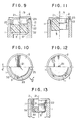
- One form of clearance 32 is between the periphery of the regulator 3 and the inner wall of the body1 (see Figs. 6 to 8, 11 to 13).
- Another is between radial ribs 35 and the inner wall of the body 1 (see Figs. 1 to 5, 9, 10).
- the clearance 32 may be formed by radial grooves. At all events it is desirable for the clearance 32 to be formed when the regulator 3 is placed in the body 1.
- the regulator there are various possible dispositions of the regulator, such as to put the regulator on the shoulder 12 of the body 1 (see Figs. 1, 3, 5, 9), to carry it by calking the lower end of the circular leg 22 of the sealing plate 2 (see Fig. 6), to unite the regulator 3 and the sealing plate 2 as one body by a soldered portion 41 by which the regulator 3 is soldered directly to the sealing plate (Fig. 7), to spigot the upper portion of the regulator into the aperture formed by the circular leg 22 of the sealing plate 2 (see Figs. 8 and 13), to fix the regulator to the sealing plate in a body (Fig. 11), etc.
- Fig. 8 shows a filter 51 supported against the underside of the orifice 31 so that the orifice 31 may not be clogged with residual swarf in the body.
- the filter 51 does not have a regulating function corresponding to that described for the orifice 31. Though such a filter is not shown in Figs. 1 to 7, the same effect can be obtained by providing such a filter at the underside of the orifice in each of those embodiments.
- a filter which is essentially different from the filter 51 of the embodiment of Fig. 8, is used as a gas flow regulator in the embodiments of Figs. 9 to 13.
- the filter is of the continuous foam type, and the interstices are selected for a certain pressure of gas.
- the filter regulates gas flow, either alone or in combination with the orifice 31, such that the regulated gas flow is sufficient to actuate a device which uses the gas (for example an oxygen inhaler) but is not enough to move the cartridge by reaction even if the cartridge is in a state where the sealing plate has been broken and the gas can flow out freely.
- Fig. 13 shows a regulator 3 which consists of a cylinder portion 3b with the orifice 31 and a filter portion 3a.
- the filter portion 3a can be thinner than in the embodiments of Figs. 9 and 11.
- the top of the regulator 3 is pressed onto the underside of the sealing plate 2.
- the upper inner portion of the regulator is closely fitted onto the outer periphery of the ciruclar leg 22, and in the embodiments of Figs. 5 and 9, the lower portion of the circular leg 22 is pressed into the regulator 3.
- the gas within the body 1 expands and the pressure increases.
- the sealing plate 2 begins to bend outwardly and a hair crack through the bottom of the limited recess 12 forms.
- the gas in the boy begins to flow out gradually through the crack and an explosion of the body 1 is avoided.
- the sealing plate 2 is pierced by mischief or the cartridge is removed from the piercing device with some gas remaining in it the rate of escape of gas is kept fixed by the regulator 3 so that the cartridge does not fly and damage is not caused to men and beasts or structures.
- the diameter of the orifice 31 required to avoid the cartridge taking off is, in the case of C0 2 gas calculated as follows.
- the diameter of the orifice 31 of the regulator 3 and the size of the interstices of the filter can be selected so that they can secure effective quantity of gas flow at the usual temperature.
- the diameter is about 0.6 mm in the case of 0.3 mm 2 as an example among sectional areas of the orifice from 0.03-0.3 mm 2 , which are cited by the inventor.
- the time spent for charging approximately 60 g of C0 2 gas in a cartridge having a capacity of 95 cc was about 3.4 seconds, where the diameter of the orifice was 0.6 mm, and was 1.4 seconds in the case of a cartridge which embodied the present invention in which the gas is charged through the clearance 32 between the regulator 3 and the body 1. Indeed the gas has been charged more quickly by the order of 2.4 times or more.
Landscapes
- Engineering & Computer Science (AREA)
- Mechanical Engineering (AREA)
- General Engineering & Computer Science (AREA)
- Filling Or Discharging Of Gas Storage Vessels (AREA)
Claims (10)
Applications Claiming Priority (4)
| Application Number | Priority Date | Filing Date | Title |
|---|---|---|---|
| JP113289/85 | 1985-05-28 | ||
| JP11328985A JPS61274200A (ja) | 1985-05-28 | 1985-05-28 | 二重安全装置付高圧ガス容器 |
| JP153383/85 | 1985-07-13 | ||
| JP15338385A JPS6217500A (ja) | 1985-07-13 | 1985-07-13 | 二重安全装置付高圧ガス容器 |
Publications (3)
| Publication Number | Publication Date |
|---|---|
| EP0204503A2 EP0204503A2 (de) | 1986-12-10 |
| EP0204503A3 EP0204503A3 (en) | 1987-09-02 |
| EP0204503B1 true EP0204503B1 (de) | 1990-08-01 |
Family
ID=26452283
Family Applications (1)
| Application Number | Title | Priority Date | Filing Date |
|---|---|---|---|
| EP19860304055 Expired EP0204503B1 (de) | 1985-05-28 | 1986-05-28 | Hochdruckgaspatrone |
Country Status (2)
| Country | Link |
|---|---|
| EP (1) | EP0204503B1 (de) |
| DE (1) | DE3673076D1 (de) |
Families Citing this family (2)
| Publication number | Priority date | Publication date | Assignee | Title |
|---|---|---|---|---|
| FR2723172B1 (fr) * | 1994-07-27 | 1997-01-24 | Fromentin Laurent | Dispositif de securite pour raccord de bouteille renfermant un fluide et ensemble comprenant un teldispositif |
| DE50307004D1 (de) * | 2003-01-07 | 2007-05-24 | Behr France Hambach Sarl | Kondensator mit Sammelbehälter und Schutzkappe |
Family Cites Families (3)
| Publication number | Priority date | Publication date | Assignee | Title |
|---|---|---|---|---|
| US2685383A (en) * | 1952-09-20 | 1954-08-03 | Knapp Monarch Co | Pressure bulb cap |
| US3623495A (en) * | 1967-11-02 | 1971-11-30 | Karl Friedrich Erb | Pressure-relief valve and diaphragm for such valve |
| JPS5634240Y2 (de) * | 1977-11-22 | 1981-08-13 |
-
1986
- 1986-05-28 EP EP19860304055 patent/EP0204503B1/de not_active Expired
- 1986-05-28 DE DE8686304055T patent/DE3673076D1/de not_active Expired - Lifetime
Also Published As
| Publication number | Publication date |
|---|---|
| DE3673076D1 (de) | 1990-09-06 |
| EP0204503A2 (de) | 1986-12-10 |
| EP0204503A3 (en) | 1987-09-02 |
Similar Documents
| Publication | Publication Date | Title |
|---|---|---|
| JPS59130530A (ja) | 推進薬増大型与圧ガス分配装置及びその製造方法 | |
| KR100386001B1 (ko) | 축전지 배터리 내에 생성된 연기를 배출시키는 장치 | |
| KR102805102B1 (ko) | 연료전지 차량의 온도감응식 압력안전장치 | |
| US5069134A (en) | Flameless expulsion grenade | |
| US2400242A (en) | Motor | |
| US4278637A (en) | Chemical oxygen generator | |
| US2684180A (en) | Stored pressure medium container with discharge control | |
| US4660714A (en) | Safety gas container | |
| US6976544B2 (en) | Sprinkler | |
| US2717042A (en) | Impact operated valve | |
| US3245578A (en) | Temperature responsive pressure relief for containers | |
| EP0204503A2 (de) | Hochdruckgaspatrone | |
| US4832224A (en) | High pressure gas cartridges with a double safety device | |
| US4452275A (en) | Safety device for an accumulator | |
| JPH0668333B2 (ja) | 温度応答圧力逃がしの方法とその装置 | |
| US6062258A (en) | Gas pressure regulator having burn-out protection system | |
| US4527635A (en) | Automatic fire extinguishing apparatus | |
| US3881394A (en) | Gas generator assembly | |
| US3664557A (en) | Bistable safety dispensing valve for fluid dispensers | |
| US2876846A (en) | Fire extinguisher head assembly | |
| US2741319A (en) | Cartridge closure with orifice strainer | |
| CN219832758U (zh) | 一种具备消防系统的电池插箱及用电设备 | |
| KR20220118730A (ko) | 수류탄형 소화기 | |
| US4256698A (en) | Chemical cartridge for respirators | |
| US4098220A (en) | Alarm |
Legal Events
| Date | Code | Title | Description |
|---|---|---|---|
| PUAI | Public reference made under article 153(3) epc to a published international application that has entered the european phase |
Free format text: ORIGINAL CODE: 0009012 |
|
| AK | Designated contracting states |
Kind code of ref document: A2 Designated state(s): DE FR GB IT NL |
|
| PUAL | Search report despatched |
Free format text: ORIGINAL CODE: 0009013 |
|
| AK | Designated contracting states |
Kind code of ref document: A3 Designated state(s): DE FR GB IT NL |
|
| 17P | Request for examination filed |
Effective date: 19880202 |
|
| 17Q | First examination report despatched |
Effective date: 19880701 |
|
| GRAA | (expected) grant |
Free format text: ORIGINAL CODE: 0009210 |
|
| AK | Designated contracting states |
Kind code of ref document: B1 Designated state(s): DE FR GB IT NL |
|
| ITF | It: translation for a ep patent filed | ||
| REF | Corresponds to: |
Ref document number: 3673076 Country of ref document: DE Date of ref document: 19900906 |
|
| ET | Fr: translation filed | ||
| PLBE | No opposition filed within time limit |
Free format text: ORIGINAL CODE: 0009261 |
|
| STAA | Information on the status of an ep patent application or granted ep patent |
Free format text: STATUS: NO OPPOSITION FILED WITHIN TIME LIMIT |
|
| 26N | No opposition filed | ||
| ITTA | It: last paid annual fee | ||
| REG | Reference to a national code |
Ref country code: GB Ref legal event code: IF02 |
|
| PGFP | Annual fee paid to national office [announced via postgrant information from national office to epo] |
Ref country code: FR Payment date: 20050425 Year of fee payment: 20 |
|
| PGFP | Annual fee paid to national office [announced via postgrant information from national office to epo] |
Ref country code: IT Payment date: 20050513 Year of fee payment: 20 |
|
| PGFP | Annual fee paid to national office [announced via postgrant information from national office to epo] |
Ref country code: GB Payment date: 20050516 Year of fee payment: 20 |
|
| PGFP | Annual fee paid to national office [announced via postgrant information from national office to epo] |
Ref country code: NL Payment date: 20050531 Year of fee payment: 20 |
|
| PGFP | Annual fee paid to national office [announced via postgrant information from national office to epo] |
Ref country code: DE Payment date: 20050629 Year of fee payment: 20 |
|
| PG25 | Lapsed in a contracting state [announced via postgrant information from national office to epo] |
Ref country code: GB Free format text: LAPSE BECAUSE OF EXPIRATION OF PROTECTION Effective date: 20060527 |
|
| PG25 | Lapsed in a contracting state [announced via postgrant information from national office to epo] |
Ref country code: NL Free format text: LAPSE BECAUSE OF EXPIRATION OF PROTECTION Effective date: 20060528 |
|
| REG | Reference to a national code |
Ref country code: GB Ref legal event code: PE20 |
|
| NLV7 | Nl: ceased due to reaching the maximum lifetime of a patent |
Effective date: 20060528 |