EP0204486A2 - Resin-laminated rubber plugs and manufacture thereof - Google Patents
Resin-laminated rubber plugs and manufacture thereof Download PDFInfo
- Publication number
- EP0204486A2 EP0204486A2 EP86304001A EP86304001A EP0204486A2 EP 0204486 A2 EP0204486 A2 EP 0204486A2 EP 86304001 A EP86304001 A EP 86304001A EP 86304001 A EP86304001 A EP 86304001A EP 0204486 A2 EP0204486 A2 EP 0204486A2
- Authority
- EP
- European Patent Office
- Prior art keywords
- mould
- rubber
- resin
- plug
- laminated
- Prior art date
- Legal status (The legal status is an assumption and is not a legal conclusion. Google has not performed a legal analysis and makes no representation as to the accuracy of the status listed.)
- Granted
Links
- 229920001971 elastomer Polymers 0.000 title claims abstract description 45
- 239000005060 rubber Substances 0.000 title claims abstract description 45
- 238000004519 manufacturing process Methods 0.000 title claims description 7
- 239000011347 resin Substances 0.000 claims abstract description 17
- 229920005989 resin Polymers 0.000 claims abstract description 17
- 238000000465 moulding Methods 0.000 claims abstract description 9
- 238000000034 method Methods 0.000 claims description 18
- 229910052751 metal Inorganic materials 0.000 claims description 10
- 239000002184 metal Substances 0.000 claims description 10
- 125000001153 fluoro group Chemical group F* 0.000 claims description 8
- 229920000642 polymer Polymers 0.000 claims description 6
- 150000001875 compounds Chemical class 0.000 claims description 5
- 229920000840 ethylene tetrafluoroethylene copolymer Polymers 0.000 claims description 3
- 238000007731 hot pressing Methods 0.000 claims description 3
- 239000000126 substance Substances 0.000 claims description 3
- BQCIDUSAKPWEOX-UHFFFAOYSA-N 1,1-Difluoroethene Chemical compound FC(F)=C BQCIDUSAKPWEOX-UHFFFAOYSA-N 0.000 claims description 2
- UUAGAQFQZIEFAH-UHFFFAOYSA-N chlorotrifluoroethylene Chemical group FC(F)=C(F)Cl UUAGAQFQZIEFAH-UHFFFAOYSA-N 0.000 claims description 2
- 229920001577 copolymer Polymers 0.000 claims description 2
- 229920001038 ethylene copolymer Polymers 0.000 claims description 2
- 229920002620 polyvinyl fluoride Polymers 0.000 claims description 2
- 239000011253 protective coating Substances 0.000 claims description 2
- BFKJFAAPBSQJPD-UHFFFAOYSA-N tetrafluoroethene Chemical group FC(F)=C(F)F BFKJFAAPBSQJPD-UHFFFAOYSA-N 0.000 claims description 2
- -1 trifluorochloroethylene-ethylene Chemical group 0.000 claims 1
- 239000011248 coating agent Substances 0.000 abstract description 2
- 238000000576 coating method Methods 0.000 abstract description 2
- 239000010410 layer Substances 0.000 description 4
- 239000003795 chemical substances by application Substances 0.000 description 3
- 238000004108 freeze drying Methods 0.000 description 3
- 239000000463 material Substances 0.000 description 3
- 239000000825 pharmaceutical preparation Substances 0.000 description 3
- IJGRMHOSHXDMSA-UHFFFAOYSA-N Atomic nitrogen Chemical compound N#N IJGRMHOSHXDMSA-UHFFFAOYSA-N 0.000 description 2
- 239000004411 aluminium Substances 0.000 description 2
- 229910052782 aluminium Inorganic materials 0.000 description 2
- XAGFODPZIPBFFR-UHFFFAOYSA-N aluminium Chemical compound [Al] XAGFODPZIPBFFR-UHFFFAOYSA-N 0.000 description 2
- 229920005549 butyl rubber Polymers 0.000 description 2
- 238000013329 compounding Methods 0.000 description 2
- 229940127557 pharmaceutical product Drugs 0.000 description 2
- 230000001681 protective effect Effects 0.000 description 2
- 239000011241 protective layer Substances 0.000 description 2
- 229930186147 Cephalosporin Natural products 0.000 description 1
- 244000043261 Hevea brasiliensis Species 0.000 description 1
- 239000005062 Polybutadiene Substances 0.000 description 1
- 230000015572 biosynthetic process Effects 0.000 description 1
- 229940124587 cephalosporin Drugs 0.000 description 1
- 150000001780 cephalosporins Chemical class 0.000 description 1
- 238000011109 contamination Methods 0.000 description 1
- 230000006866 deterioration Effects 0.000 description 1
- 230000000694 effects Effects 0.000 description 1
- HQQADJVZYDDRJT-UHFFFAOYSA-N ethene;prop-1-ene Chemical group C=C.CC=C HQQADJVZYDDRJT-UHFFFAOYSA-N 0.000 description 1
- 239000010419 fine particle Substances 0.000 description 1
- 229920005555 halobutyl Polymers 0.000 description 1
- 238000010438 heat treatment Methods 0.000 description 1
- 239000011261 inert gas Substances 0.000 description 1
- 229920003049 isoprene rubber Polymers 0.000 description 1
- 238000003475 lamination Methods 0.000 description 1
- 229940127554 medical product Drugs 0.000 description 1
- 229920003052 natural elastomer Polymers 0.000 description 1
- 229920001194 natural rubber Polymers 0.000 description 1
- 229910052757 nitrogen Inorganic materials 0.000 description 1
- 229920002857 polybutadiene Polymers 0.000 description 1
- 238000003825 pressing Methods 0.000 description 1
- 229920002379 silicone rubber Polymers 0.000 description 1
- 239000004945 silicone rubber Substances 0.000 description 1
- 229920003051 synthetic elastomer Polymers 0.000 description 1
- 229920001897 terpolymer Polymers 0.000 description 1
- 238000004073 vulcanization Methods 0.000 description 1
Images


Classifications
-
- B—PERFORMING OPERATIONS; TRANSPORTING
- B65—CONVEYING; PACKING; STORING; HANDLING THIN OR FILAMENTARY MATERIAL
- B65D—CONTAINERS FOR STORAGE OR TRANSPORT OF ARTICLES OR MATERIALS, e.g. BAGS, BARRELS, BOTTLES, BOXES, CANS, CARTONS, CRATES, DRUMS, JARS, TANKS, HOPPERS, FORWARDING CONTAINERS; ACCESSORIES, CLOSURES, OR FITTINGS THEREFOR; PACKAGING ELEMENTS; PACKAGES
- B65D51/00—Closures not otherwise provided for
- B65D51/24—Closures not otherwise provided for combined or co-operating with auxiliary devices for non-closing purposes
- B65D51/241—Closures not otherwise provided for combined or co-operating with auxiliary devices for non-closing purposes provided with freeze-drying means
-
- B—PERFORMING OPERATIONS; TRANSPORTING
- B29—WORKING OF PLASTICS; WORKING OF SUBSTANCES IN A PLASTIC STATE IN GENERAL
- B29C—SHAPING OR JOINING OF PLASTICS; SHAPING OF MATERIAL IN A PLASTIC STATE, NOT OTHERWISE PROVIDED FOR; AFTER-TREATMENT OF THE SHAPED PRODUCTS, e.g. REPAIRING
- B29C43/00—Compression moulding, i.e. applying external pressure to flow the moulding material; Apparatus therefor
- B29C43/02—Compression moulding, i.e. applying external pressure to flow the moulding material; Apparatus therefor of articles of definite length, i.e. discrete articles
- B29C43/14—Compression moulding, i.e. applying external pressure to flow the moulding material; Apparatus therefor of articles of definite length, i.e. discrete articles in several steps
- B29C43/146—Compression moulding, i.e. applying external pressure to flow the moulding material; Apparatus therefor of articles of definite length, i.e. discrete articles in several steps for making multilayered articles
-
- B—PERFORMING OPERATIONS; TRANSPORTING
- B29—WORKING OF PLASTICS; WORKING OF SUBSTANCES IN A PLASTIC STATE IN GENERAL
- B29C—SHAPING OR JOINING OF PLASTICS; SHAPING OF MATERIAL IN A PLASTIC STATE, NOT OTHERWISE PROVIDED FOR; AFTER-TREATMENT OF THE SHAPED PRODUCTS, e.g. REPAIRING
- B29C43/00—Compression moulding, i.e. applying external pressure to flow the moulding material; Apparatus therefor
- B29C43/02—Compression moulding, i.e. applying external pressure to flow the moulding material; Apparatus therefor of articles of definite length, i.e. discrete articles
- B29C43/18—Compression moulding, i.e. applying external pressure to flow the moulding material; Apparatus therefor of articles of definite length, i.e. discrete articles incorporating preformed parts or layers, e.g. compression moulding around inserts or for coating articles
-
- B—PERFORMING OPERATIONS; TRANSPORTING
- B29—WORKING OF PLASTICS; WORKING OF SUBSTANCES IN A PLASTIC STATE IN GENERAL
- B29C—SHAPING OR JOINING OF PLASTICS; SHAPING OF MATERIAL IN A PLASTIC STATE, NOT OTHERWISE PROVIDED FOR; AFTER-TREATMENT OF THE SHAPED PRODUCTS, e.g. REPAIRING
- B29C43/00—Compression moulding, i.e. applying external pressure to flow the moulding material; Apparatus therefor
- B29C43/02—Compression moulding, i.e. applying external pressure to flow the moulding material; Apparatus therefor of articles of definite length, i.e. discrete articles
- B29C43/20—Making multilayered or multicoloured articles
- B29C43/203—Making multilayered articles
-
- B—PERFORMING OPERATIONS; TRANSPORTING
- B29—WORKING OF PLASTICS; WORKING OF SUBSTANCES IN A PLASTIC STATE IN GENERAL
- B29C—SHAPING OR JOINING OF PLASTICS; SHAPING OF MATERIAL IN A PLASTIC STATE, NOT OTHERWISE PROVIDED FOR; AFTER-TREATMENT OF THE SHAPED PRODUCTS, e.g. REPAIRING
- B29C43/00—Compression moulding, i.e. applying external pressure to flow the moulding material; Apparatus therefor
- B29C43/02—Compression moulding, i.e. applying external pressure to flow the moulding material; Apparatus therefor of articles of definite length, i.e. discrete articles
- B29C43/14—Compression moulding, i.e. applying external pressure to flow the moulding material; Apparatus therefor of articles of definite length, i.e. discrete articles in several steps
- B29C43/146—Compression moulding, i.e. applying external pressure to flow the moulding material; Apparatus therefor of articles of definite length, i.e. discrete articles in several steps for making multilayered articles
- B29C2043/148—Compression moulding, i.e. applying external pressure to flow the moulding material; Apparatus therefor of articles of definite length, i.e. discrete articles in several steps for making multilayered articles using different moulds
-
- B—PERFORMING OPERATIONS; TRANSPORTING
- B29—WORKING OF PLASTICS; WORKING OF SUBSTANCES IN A PLASTIC STATE IN GENERAL
- B29K—INDEXING SCHEME ASSOCIATED WITH SUBCLASSES B29B, B29C OR B29D, RELATING TO MOULDING MATERIALS OR TO MATERIALS FOR MOULDS, REINFORCEMENTS, FILLERS OR PREFORMED PARTS, e.g. INSERTS
- B29K2021/00—Use of unspecified rubbers as moulding material
-
- B—PERFORMING OPERATIONS; TRANSPORTING
- B29—WORKING OF PLASTICS; WORKING OF SUBSTANCES IN A PLASTIC STATE IN GENERAL
- B29K—INDEXING SCHEME ASSOCIATED WITH SUBCLASSES B29B, B29C OR B29D, RELATING TO MOULDING MATERIALS OR TO MATERIALS FOR MOULDS, REINFORCEMENTS, FILLERS OR PREFORMED PARTS, e.g. INSERTS
- B29K2027/00—Use of polyvinylhalogenides or derivatives thereof as moulding material
- B29K2027/12—Use of polyvinylhalogenides or derivatives thereof as moulding material containing fluorine
-
- B—PERFORMING OPERATIONS; TRANSPORTING
- B29—WORKING OF PLASTICS; WORKING OF SUBSTANCES IN A PLASTIC STATE IN GENERAL
- B29L—INDEXING SCHEME ASSOCIATED WITH SUBCLASS B29C, RELATING TO PARTICULAR ARTICLES
- B29L2031/00—Other particular articles
- B29L2031/56—Stoppers or lids for bottles, jars, or the like, e.g. closures
- B29L2031/565—Stoppers or lids for bottles, jars, or the like, e.g. closures for containers
Definitions
- This invention relates to rubber closures or plugs for medical vials or bottles and the manufacture of such closures or plugs.
- rubber plugs for vials which contain vulcanisation accelerators or other compounding agents render medical or pharmaceutical products which are kept in containers closed by such rubber plugs liable to deterioration, usually by contamination with fine particles of the aforementioned accelerators or other agents.
- This proposal comprises placing a chemical resistant resin film 34 and a non-vulcanised rubber sheet 35 in that order over a lower metal mould 2 which has an annular recess 33 for forming the hollow annular body portion 36 of the rubber plug.
- An upper mould 31 is placed over the sheet 35 and the film 34 and sheet 35 are pressed between the moulds to form a body 36 of which the lower surface is covered with the resin film and of which the upper rubber surface is exposed.
- a flange 37 formed during moulding is cut off to provide the plug body 36 with an outside diameter of, at most, two thirds that of the intended outside diameter of the head of the plug.
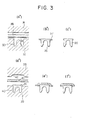
- the head is formed by a remoulding technique in which a layer of non-vulcanised rubber 41 is placed over the body 36, held in a recess 40 in a lower mould 39, and a head-forming mould 38 is pressed over the layer 11 to form the head of the plug; unwanted material forced out laterally from the head is removed to make the final form of the plug, as shown in Figure 3 (f").
- Figure 1 illustrates one preferred method of making a rubber plug according to the invention.
- a layer or plate of non-vulcanised rubber 5 is provided with a lower protective layer 6, preferably of fluoro resin, and the laminate thus formed is pressed between an upper mould 1 and a lower mould 2.
- the lower mould has an annular recess 3, for forming the annular body part of the plug; in this method the central portion P of the lower mould protrudes above the outer rim of a annular recess 3.
- the laminate is pressed and vulcanised by the heated moulds.
- the upper mould has a truncated conical recess 4 of a diameter substantially that of the outside diameter of the recess 3 in the lower mould.
- the first moulding step produces as shown in Figure 1 (b) a body part 7 which has a burr or sprue 8, which is removed, as shown by Figure 1 (c).
- a second moulding stage is performed as shown in Figure 1 (d).
- the previously formed body part 7 is inserted in a lower mould 10 of which the annular recess 11 is somewhat deeper than the recess 3 in the mould 2.
- the central portion is of lesser height than the central part P of the mould 2. Otherwise the recess 11 of the mould 10 conforms to the shape of the body part 7 of the plug.
- a plate 13 of non-vulcanised compound rubber which is hot pressed and vulcanised by means of an upper mould 9 of which the recess 12 conforms to the desired shape of the upper surface of the head or cap of the plug.
- this process forms a plug in which part of the outer surface of the body of the plug is formed in the second stage, in this preferred method because the recess 11 is deeper than the recess 3, and accordingly the plug is formed such that the upper region 16 of the body next to the cap 14 is formed free of the protective layer covering the lower portion and the inside of the hollow body of the plug. Unwanted material 15 formed during the second moulding stage is re- ' moved.
- Figure 2 illustrates an alternative method which is similar to that shown in Figure 1 except that the mould 1 has no recess 4, whereby the upper surface of the body part T is made flat.
- this surface is preferably formed as a frusto cone to increase the internal height of the body portion. This enables the central part of the plug to be made thinner (facilitating its piercing by a hyper- dermic needle) without requiring any hollowing of the cap, which can thereby be securely bonded to the body portion.
- the non-vulcanised compound rubber preferably used in the present invention may be a synthetic or natural rubber such as butyl rubber, isoprene rubber, butadiene rubber, halogenated butyl rubber, ethylene propylene terpolymer, silicone rubber and similar materials.
- the protective coating there may be employed tetrafluoroethylene polymer, trifluorochloroethylene polymer, tetrafluoroethylene-hexafluoropropylene copolymer, vinylidene fluoride polymer, vinyl fluoride polymer, tetrafluoroethylene-ethylene copolymer or trifluorochlorothylene-ethylene copolymer.
- the protective resin film has preferably a thickness between 0.002 and 0.5 mm.
- each moulding stage according to Figure 1 or Figure 2 depends upon the fluoro resin layer employed, the particular rubber and compounding agents, the thickness of the rubber and so on.
- the first moulding stage is preferably carried out at a temperature between 150 and 175°C and a pressure between 40 and 70 kgtcm2 for about 10 minutes, particularly 100 to 165°C and about 50 kgtcm 2 for about 15 minutes in an example in which the protective film is a tetrafluoroethylene-ethylene copolymer film and the compound rubber contains 58% of butyl rubber.
- the hot pressing and vulcanising step shown in Figure 1(d) is preferably carried out at a temperature of 160 to 175°C for about 8 minutes.
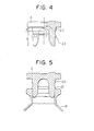
- the outer surface of the body may be of the simple form shown in Figure 1(f) but may be in more complex form as shown, for example, in Figure 4 wherein the upper part of the outer surface of the body has a shoulder or step 22 and the lower part of the outer surface of the body has a projection or barb 23.
- the various moulds must of course be modified accordingly.
- the particular plug shown in Figure 4 has a body part of which the height of the shoulder - (corresponding to the exposed rubber surface of the body) is x, and the lower portion of the outer surface of the body has a height y.
- the internal height of the body is greater than the height y, the difference in height m being preferably in the range 0.1 to 5mm.
- the airtightness when a vial is closed by the stopper is mainly determined by the height x which may be from 0.1 to 5mm.
- the pierceability of the head may be increased by an increase in the dimension m.
- the protrusion or barb 23 may determine the position of the plug when a vial is half closed by the plug as shown in Figure 5; the protrusion prevents the stopper from sinking by virtue of the slippery surface of the fluoro-resin film.
- a vial B is preferably half closed as shown in Figure 5, subjected to freeze drying in a freeze drying chamber and then completely closed by the plug, as shown in Figure 6.
- the stopper may be further secured by means of an aluminium cap C as shown in Figure 7.
- Figures 8 to 10 illustrate further details of a stopper as generally shown in Figure 4.
- the protrusions 24 on the body portion are in the form of semi-trigonal pyramids.
- the upper end 16 of the body is not but the lower portion 17 is provided with a complete coating of the chemical-resistant resin.
- the ratio L1 to L2 should preferably be between 1.7 and 1.5.
- the rubber plug When the container or vial is in a half closed state, there is a danger that the rubber plug may incline or slip out of the mouth of the vial. To inhibit the tilting of the rubber plug, it may be provided with a further protrusion or set of protrusions 27 below the protrusion or set of protrustions 24.
- the upper surface of the cap of the plug may be provided with ribs 45 and a central recess 46.
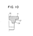
- Figure 10 illustrates the formation of the upper portion 16 of the plug with two shoulders 37 and 38, of which the lower shoulder 38 is bevelled.
Abstract
Description
- This invention relates to rubber closures or plugs for medical vials or bottles and the manufacture of such closures or plugs.
- It is known that rubber plugs for vials which contain vulcanisation accelerators or other compounding agents render medical or pharmaceutical products which are kept in containers closed by such rubber plugs liable to deterioration, usually by contamination with fine particles of the aforementioned accelerators or other agents.
- It has been proposed to laminate all the body portion of a rubber plug with a fluoro resin to prevent the rubber of the body portion from direct contact with a solution or other pharmaceutical product kept within the container closed by the plug. Examples are given by Japanese Patent Publications Nos. 9119/1979 and 1355/1977 and Japanese Utility Model Publications Nos. 27753/1969, 17831/1970 and 21346/1974. It has also been proposed to produce a rubber plug by means of a two stage moulding, as shown in Figure 3, and as also described in Japanese Patent Publication No. 53184/1982. This proposal comprises placing a chemical resistant resin film 34 and a
non-vulcanised rubber sheet 35 in that order over a lower metal mould 2 which has anannular recess 33 for forming the hollowannular body portion 36 of the rubber plug. Anupper mould 31 is placed over thesheet 35 and the film 34 andsheet 35 are pressed between the moulds to form abody 36 of which the lower surface is covered with the resin film and of which the upper rubber surface is exposed. Aflange 37 formed during moulding is cut off to provide theplug body 36 with an outside diameter of, at most, two thirds that of the intended outside diameter of the head of the plug. The head is formed by a remoulding technique in which a layer of non-vulcanised rubber 41 is placed over thebody 36, held in arecess 40 in alower mould 39, and a head-formingmould 38 is pressed over the layer 11 to form the head of the plug; unwanted material forced out laterally from the head is removed to make the final form of the plug, as shown in Figure 3 (f"). - In order to improve the quality of some pharmaceutical preparations such as cephalosporin, it is necessary to maintain the airtightness of a vial for a very long time. It has been proposed to provide a resin-laminated rubber plug A as shown in Figure 4. In such a plug the outer circumference of the upper end 2 of the annular body of the plug is free from resin lamination, as explained in European Patent Application No. 0172613 filed 5th June 1985.
- It is an object of the present invention to provide an improved rubber plug. It is an alternative or additional object of the present invention to provide a resin-laminated rubber closure in which the inside height of a hollow body is greater than the outside height. It is a further alternative or additional object of the invention to provide a process for the production of a resin-laminated rubber plug, in which the outer circumference of the upper end of an annular body of the plug is not laminated, whereby the rubber surface is exposed.
-
- Figures 1 and 2 are schematic views illustrating the production of rubber plugs according to the invention;
- Figure 3 is a schematic drawing illustrating a previously known procedure for producing a rubber plug;
- Figure 4 is a side sectional view of a rubber plug which can be made according to the present invention;
- Figure 5 is side sectional view of the rubber plug of Figure 4, in a position partly closing the mouth of a vial;
- Figure 6 is a side sectional view of the rubber plug of Figure 4, shown as completely closing the mouth of a vial;
- Figure 7 is a side sectional view of a rubber plug made according to the invention, completely closing the mouth of a vial and being fastened by an aluminium cap;
- Figure 8 is a plan view of another rubber plug made in accordance with the invention;
- Figure 9 is a partly sectioned side view taken on line I-I' in Figure 8; and
- Figure 10 is a part sectional side view taken on the line II-II' in Figure 8.
- Figure 1 illustrates one preferred method of making a rubber plug according to the invention. As is shown in Figure 1 (a) a layer or plate of
non-vulcanised rubber 5 is provided with a lower protective layer 6, preferably of fluoro resin, and the laminate thus formed is pressed between an upper mould 1 and a lower mould 2. The lower mould has anannular recess 3, for forming the annular body part of the plug; in this method the central portion P of the lower mould protrudes above the outer rim of aannular recess 3. The laminate is pressed and vulcanised by the heated moulds. Preferably the upper mould has a truncatedconical recess 4 of a diameter substantially that of the outside diameter of therecess 3 in the lower mould. The first moulding step produces as shown in Figure 1 (b) abody part 7 which has a burr orsprue 8, which is removed, as shown by Figure 1 (c). - A second moulding stage is performed as shown in Figure 1 (d). The previously formed
body part 7 is inserted in alower mould 10 of which the annular recess 11 is somewhat deeper than therecess 3 in the mould 2. In themould part 10, the central portion is of lesser height than the central part P of the mould 2. Otherwise the recess 11 of themould 10 conforms to the shape of thebody part 7 of the plug. Over thepart 7 is disposed aplate 13 of non-vulcanised compound rubber, which is hot pressed and vulcanised by means of an upper mould 9 of which the recess 12 conforms to the desired shape of the upper surface of the head or cap of the plug. As may be seen from Figure 1 (d),(e) and (f) this process forms a plug in which part of the outer surface of the body of the plug is formed in the second stage, in this preferred method because the recess 11 is deeper than therecess 3, and accordingly the plug is formed such that theupper region 16 of the body next to thecap 14 is formed free of the protective layer covering the lower portion and the inside of the hollow body of the plug.Unwanted material 15 formed during the second moulding stage is re- ' moved. - Figure 2 illustrates an alternative method which is similar to that shown in Figure 1 except that the mould 1 has no
recess 4, whereby the upper surface of the body part T is made flat. However, this surface is preferably formed as a frusto cone to increase the internal height of the body portion. This enables the central part of the plug to be made thinner (facilitating its piercing by a hyper- dermic needle) without requiring any hollowing of the cap, which can thereby be securely bonded to the body portion. - The non-vulcanised compound rubber preferably used in the present invention may be a synthetic or natural rubber such as butyl rubber, isoprene rubber, butadiene rubber, halogenated butyl rubber, ethylene propylene terpolymer, silicone rubber and similar materials. For the protective coating, there may be employed tetrafluoroethylene polymer, trifluorochloroethylene polymer, tetrafluoroethylene-hexafluoropropylene copolymer, vinylidene fluoride polymer, vinyl fluoride polymer, tetrafluoroethylene-ethylene copolymer or trifluorochlorothylene-ethylene copolymer. The protective resin film has preferably a thickness between 0.002 and 0.5 mm.
- The pressing and heating conditions in each moulding stage according to Figure 1 or Figure 2 depend upon the fluoro resin layer employed, the particular rubber and compounding agents, the thickness of the rubber and so on. However, the first moulding stage is preferably carried out at a temperature between 150 and 175°C and a pressure between 40 and 70 kgtcm2 for about 10 minutes, particularly 100 to 165°C and about 50 kgtcm2 for about 15 minutes in an example in which the protective film is a tetrafluoroethylene-ethylene copolymer film and the compound rubber contains 58% of butyl rubber. The hot pressing and vulcanising step shown in Figure 1(d) is preferably carried out at a temperature of 160 to 175°C for about 8 minutes.
- The outer surface of the body may be of the simple form shown in Figure 1(f) but may be in more complex form as shown, for example, in Figure 4 wherein the upper part of the outer surface of the body has a shoulder or
step 22 and the lower part of the outer surface of the body has a projection orbarb 23. The various moulds must of course be modified accordingly. - The particular plug shown in Figure 4 has a body part of which the height of the shoulder - (corresponding to the exposed rubber surface of the body) is x, and the lower portion of the outer surface of the body has a height y. In this embodiment the internal height of the body is greater than the height y, the difference in height m being preferably in the range 0.1 to 5mm. The airtightness when a vial is closed by the stopper is mainly determined by the height x which may be from 0.1 to 5mm. The pierceability of the head may be increased by an increase in the dimension m.
- The protrusion or barb 23 (which may have a height between 0.1 and 1mm) may determine the position of the plug when a vial is half closed by the plug as shown in Figure 5; the protrusion prevents the stopper from sinking by virtue of the slippery surface of the fluoro-resin film. In use, a vial B is preferably half closed as shown in Figure 5, subjected to freeze drying in a freeze drying chamber and then completely closed by the plug, as shown in Figure 6. The stopper may be further secured by means of an aluminium cap C as shown in Figure 7.
- When a rubber plug A is put into a vial B as shown in Figure 5, the plug is maintained at a constant height by the
protrusions 4 even if the diameter of the mouth of a vial should alter from vial to vial. A constant quantity of vapour may be exhausted and a constant degree of vacuum may be held in the vial. Freeze drying may accordingly be completed in a shorter time. Complete closure is performed after the introduction of an inert gas such as nitrogen. In order to effect complete closure, a large press may be used. The protrusions on the body part act as a buffer to protect the vial from breakage. - Figures 8 to 10 illustrate further details of a stopper as generally shown in Figure 4. In this embodiment the
protrusions 24 on the body portion are in the form of semi-trigonal pyramids. Theupper end 16 of the body is not but the lower portion 17 is provided with a complete coating of the chemical-resistant resin. - If as shown in Figure 9 the height of the body from the lower rim to the ceiling of the inner portion is represented by L1 and the height from the lower rim of the body to the protrusion is L2, the ratio L1 to L2 should preferably be between 1.7 and 1.5.
- When the container or vial is in a half closed state, there is a danger that the rubber plug may incline or slip out of the mouth of the vial. To inhibit the tilting of the rubber plug, it may be provided with a further protrusion or set of
protrusions 27 below the protrusion or set ofprotrustions 24. - As shown in Figures 8 and 9, the upper surface of the cap of the plug may be provided with
ribs 45 and acentral recess 46. - Figure 10 illustrates the formation of the
upper portion 16 of the plug with twoshoulders lower shoulder 38 is bevelled.
Claims (12)
Applications Claiming Priority (4)
| Application Number | Priority Date | Filing Date | Title |
|---|---|---|---|
| JP113255/85 | 1985-05-28 | ||
| JP60113255A JPS61272134A (en) | 1985-05-28 | 1985-05-28 | Manufacture of rubber stopper for vial |
| JP106875/85 | 1985-07-15 | ||
| JP1985106875U JPH052182Y2 (en) | 1985-07-15 | 1985-07-15 |
Publications (3)
| Publication Number | Publication Date |
|---|---|
| EP0204486A2 true EP0204486A2 (en) | 1986-12-10 |
| EP0204486A3 EP0204486A3 (en) | 1987-12-09 |
| EP0204486B1 EP0204486B1 (en) | 1990-10-17 |
Family
ID=26446978
Family Applications (1)
| Application Number | Title | Priority Date | Filing Date |
|---|---|---|---|
| EP86304001A Expired - Lifetime EP0204486B1 (en) | 1985-05-28 | 1986-05-27 | Resin-laminated rubber plugs and manufacture thereof |
Country Status (3)
| Country | Link |
|---|---|
| US (2) | US5078941A (en) |
| EP (1) | EP0204486B1 (en) |
| DE (1) | DE3674949D1 (en) |
Cited By (6)
| Publication number | Priority date | Publication date | Assignee | Title |
|---|---|---|---|---|
| EP0450098A1 (en) * | 1989-10-23 | 1991-10-09 | Nissho Corporation | Production method for rubber plug for vial |
| GB2252951B (en) * | 1991-02-15 | 1995-05-31 | Pasteur Merieux Serums Vacc | Method of packaging freeze dried vaccines in syringes and plug for implementing the method |
| WO1995024301A1 (en) * | 1994-03-07 | 1995-09-14 | Wheaton Inc. | Partially laminated rubber closure |
| EP0705673A3 (en) * | 1994-09-26 | 1997-05-07 | Becton Dickinson Co | Medical articles and method therefor |
| EP2998237A1 (en) * | 2014-09-16 | 2016-03-23 | Sumitomo Rubber Industries, Ltd. | Medical rubber closure and method for manufacturing the same |
| WO2019063772A1 (en) * | 2017-09-28 | 2019-04-04 | F. Hoffmann-La Roche Ag | Vial stopper for a lyophilization vial and closure method for closing a lyophilization vial |
Families Citing this family (35)
| Publication number | Priority date | Publication date | Assignee | Title |
|---|---|---|---|---|
| US5297561A (en) * | 1989-06-15 | 1994-03-29 | Hulon Walter C | Blood collection tube assembly |
| US5064083A (en) * | 1990-03-08 | 1991-11-12 | The West Company, Incorporated | Closure device |
| DE4112209A1 (en) * | 1991-04-13 | 1992-10-15 | Behringwerke Ag | CONTAINER CLOSURE WITH PUSHABLE BODY |
| US5279606A (en) * | 1991-08-28 | 1994-01-18 | Habley Medical Technology Corporation | Non-reactive composite sealing barrier |
| ES2145124T3 (en) * | 1992-12-30 | 2000-07-01 | Abbott Lab | FINE MEMBRANE PLUG FOR NON-POINTED PENETRATING DEVICE. |
| US5377854A (en) * | 1993-04-16 | 1995-01-03 | International Technidyne Corp. | Stopper apparatus for a test tube or similar article |
| US5845797A (en) * | 1996-07-31 | 1998-12-08 | Daikyo Seiko, Ltd. | Rubber plug for drug vessel |
| JP3198065B2 (en) | 1996-08-19 | 2001-08-13 | 株式会社大協精工 | Hygiene container |
| US6074373A (en) * | 1996-10-28 | 2000-06-13 | Daikyo Seiko, Ltd. | Syringe with a luer-lok portion |
| JP3380705B2 (en) * | 1997-03-12 | 2003-02-24 | 株式会社大協精工 | Sealed rubber stopper for syringe and container |
| US6165402A (en) * | 1998-01-30 | 2000-12-26 | Abbott Laboratories | Method for making a stopper |
| JP3142521B2 (en) * | 1998-11-04 | 2001-03-07 | 大成プラス株式会社 | Needlestick stopcock and its manufacturing method |
| JP2000202837A (en) * | 1999-01-11 | 2000-07-25 | Daikyo Seiko Ltd | Manufacture of laminated rubber stopper and laminated rubber stopper |
| US6068150A (en) * | 1999-01-27 | 2000-05-30 | Coulter International Corp. | Enclosure cap for multiple piercing |
| JP3512349B2 (en) * | 1999-01-29 | 2004-03-29 | 株式会社大協精工 | Mold for columnar rubber element |
| US6558628B1 (en) * | 1999-03-05 | 2003-05-06 | Specialty Silicone Products, Inc. | Compartment cover, kit and method for forming the same |
| JP3908895B2 (en) | 1999-07-12 | 2007-04-25 | 株式会社大協精工 | Manufacturing method of rubber stopper |
| DE10122959A1 (en) | 2001-05-11 | 2002-11-21 | West Pharm Serv Drug Res Ltd | Method for producing a piston for a pharmaceutical syringe or a similar item includes a step in which surplus of the inert foil cap on the piston body is separated in a punching unit |
| JP2004189265A (en) * | 2002-12-10 | 2004-07-08 | Teruaki Ito | Plug for tubelike specimen container |
| AU2003900033A0 (en) * | 2003-01-07 | 2003-01-23 | Procork Pty Ltd | Container stopper |
| US20060226112A1 (en) * | 2005-04-06 | 2006-10-12 | Clark Douglas P | Liquid vial closure with improved anti-evaporation features |
| US20060226113A1 (en) * | 2005-04-06 | 2006-10-12 | Clark Douglas P | Liquid vial closure with improved anti-evaporation features |
| US7934614B2 (en) * | 2006-06-07 | 2011-05-03 | J. G. Finneran Associates, Inc. | Two-piece seal vial assembly |
| ES2261104B1 (en) * | 2006-06-19 | 2007-06-16 | Grifols, S.A. | "PLUG FOR STERILE PRODUCTS FRUITS AND USE OF SUCH PLUG IN STERILE DOSAGE". |
| EP2206654B1 (en) * | 2007-10-18 | 2015-07-08 | Daikyo Seiko, LTD. | Vial rubber-stopper |
| AU2009297049B2 (en) | 2008-03-05 | 2012-04-12 | Becton, Dickinson And Company | Capillary action collection device and container assembly |
| WO2009111622A2 (en) * | 2008-03-05 | 2009-09-11 | Becton, Dickinson And Company | Co-molded pierceable stopper and method for making the same |
| WO2011044569A1 (en) | 2009-10-09 | 2011-04-14 | West Pharmaceutical Services, Inc. | Elastomeric closure with barrier layer and method for its manufacture |
| US8460620B2 (en) | 2010-12-03 | 2013-06-11 | Becton, Dickinson And Company | Specimen collection container assembly |
| JP6243096B2 (en) * | 2011-11-16 | 2017-12-06 | 株式会社大協精工 | Rubber stopper for vial |
| CN103252860A (en) * | 2013-05-27 | 2013-08-21 | 盛州橡塑胶(苏州)有限公司 | Secondary forming method for freeze-dried powder laminated rubber plug |
| CN104908187A (en) * | 2015-06-30 | 2015-09-16 | 江苏博生医用新材料股份有限公司 | Novel pharmaceutical bottle stopper of composite structure and production method of novel pharmaceutical bottle stopper |
| USD820084S1 (en) * | 2015-11-12 | 2018-06-12 | David Schoen | Bottle stopper |
| CN114953652A (en) | 2017-12-15 | 2022-08-30 | 西部制药服务有限公司 | Smooth film laminated elastomeric articles |
| FR3095600B1 (en) * | 2019-05-03 | 2021-05-14 | Biomerieux Sa | CLOSURE ELEMENT FOR MICROPLATE WELLS PRESENTING VENTS AND A SLOT AND METHOD FOR ITS USE |
Citations (7)
| Publication number | Priority date | Publication date | Assignee | Title |
|---|---|---|---|---|
| US2705211A (en) * | 1950-12-16 | 1955-03-29 | Goodrich Co B F | Method of making skin covered rubber weatherstrip |
| US3705211A (en) * | 1970-07-27 | 1972-12-05 | American Cyanamid Co | Bisphosphorylated imidodithiocarbonates and methods for their preparation |
| US3760969A (en) * | 1970-09-16 | 1973-09-25 | Takeda Chemical Industries Ltd | Container closure |
| DE3231179A1 (en) * | 1981-08-24 | 1983-03-24 | Daikyo Gomu Seiko, Ltd., Tokyo | PUNCHABLE LOCKING ELEMENT FOR A CONTAINER, ESPECIALLY A MEDICAL BOTTLE |
| EP0086253A1 (en) * | 1982-02-15 | 1983-08-24 | Fuji Rubber Co. Ltd. | Method of manufacturing contact rubber structure |
| US4459256A (en) * | 1981-04-09 | 1984-07-10 | Telefonaktiebolaget Lm Ericsson | Method of manufacturing a push button keyboard |
| EP0163251A2 (en) * | 1984-05-22 | 1985-12-04 | Daikin Industries, Limited | Laminated rubber stopper |
Family Cites Families (3)
| Publication number | Priority date | Publication date | Assignee | Title |
|---|---|---|---|---|
| FR1538462A (en) * | 1967-07-24 | 1968-09-06 | Improvements made to caps, especially for therapeutic bottles | |
| US4111326A (en) * | 1976-03-04 | 1978-09-05 | Becton, Dickinson And Company | Closure for air evacuated container |
| FR2416848A1 (en) * | 1978-02-08 | 1979-09-07 | Rumpler Jean Jacques | MEDICINAL PRODUCT CONTAINER CAP |
-
1986
- 1986-05-27 DE DE8686304001T patent/DE3674949D1/en not_active Expired - Lifetime
- 1986-05-27 EP EP86304001A patent/EP0204486B1/en not_active Expired - Lifetime
-
1987
- 1987-07-17 US US07/074,987 patent/US5078941A/en not_active Expired - Lifetime
-
1988
- 1988-04-19 US US07/185,363 patent/US4915243A/en not_active Expired - Lifetime
Patent Citations (8)
| Publication number | Priority date | Publication date | Assignee | Title |
|---|---|---|---|---|
| US2705211A (en) * | 1950-12-16 | 1955-03-29 | Goodrich Co B F | Method of making skin covered rubber weatherstrip |
| US3705211A (en) * | 1970-07-27 | 1972-12-05 | American Cyanamid Co | Bisphosphorylated imidodithiocarbonates and methods for their preparation |
| US3760969A (en) * | 1970-09-16 | 1973-09-25 | Takeda Chemical Industries Ltd | Container closure |
| US4459256A (en) * | 1981-04-09 | 1984-07-10 | Telefonaktiebolaget Lm Ericsson | Method of manufacturing a push button keyboard |
| DE3231179A1 (en) * | 1981-08-24 | 1983-03-24 | Daikyo Gomu Seiko, Ltd., Tokyo | PUNCHABLE LOCKING ELEMENT FOR A CONTAINER, ESPECIALLY A MEDICAL BOTTLE |
| US4441621A (en) * | 1981-08-24 | 1984-04-10 | Takeda Chemical Industries, Ltd. | Pierceable closure member for vial |
| EP0086253A1 (en) * | 1982-02-15 | 1983-08-24 | Fuji Rubber Co. Ltd. | Method of manufacturing contact rubber structure |
| EP0163251A2 (en) * | 1984-05-22 | 1985-12-04 | Daikin Industries, Limited | Laminated rubber stopper |
Cited By (9)
| Publication number | Priority date | Publication date | Assignee | Title |
|---|---|---|---|---|
| EP0450098A1 (en) * | 1989-10-23 | 1991-10-09 | Nissho Corporation | Production method for rubber plug for vial |
| EP0450098A4 (en) * | 1989-10-23 | 1992-04-01 | Nissho Corporation | Production method for rubber plug for vial |
| GB2252951B (en) * | 1991-02-15 | 1995-05-31 | Pasteur Merieux Serums Vacc | Method of packaging freeze dried vaccines in syringes and plug for implementing the method |
| WO1995024301A1 (en) * | 1994-03-07 | 1995-09-14 | Wheaton Inc. | Partially laminated rubber closure |
| US5484566A (en) * | 1994-03-07 | 1996-01-16 | Wheaton Inc. | Method of manufacture of a partially laminated rubber closure |
| EP0705673A3 (en) * | 1994-09-26 | 1997-05-07 | Becton Dickinson Co | Medical articles and method therefor |
| EP2998237A1 (en) * | 2014-09-16 | 2016-03-23 | Sumitomo Rubber Industries, Ltd. | Medical rubber closure and method for manufacturing the same |
| WO2019063772A1 (en) * | 2017-09-28 | 2019-04-04 | F. Hoffmann-La Roche Ag | Vial stopper for a lyophilization vial and closure method for closing a lyophilization vial |
| US11577893B2 (en) | 2017-09-28 | 2023-02-14 | Hoffmann-La Roche Inc. | Vial stopper for a lyophilization vial and closure method for closing a lyophilization vial |
Also Published As
| Publication number | Publication date |
|---|---|
| EP0204486A3 (en) | 1987-12-09 |
| DE3674949D1 (en) | 1990-11-22 |
| US5078941A (en) | 1992-01-07 |
| US4915243A (en) | 1990-04-10 |
| EP0204486B1 (en) | 1990-10-17 |
Similar Documents
| Publication | Publication Date | Title |
|---|---|---|
| EP0204486B1 (en) | Resin-laminated rubber plugs and manufacture thereof | |
| US5484566A (en) | Method of manufacture of a partially laminated rubber closure | |
| US3760969A (en) | Container closure | |
| US4635807A (en) | Stopper for sterile fluid containers | |
| EP0450096A1 (en) | Rubber plug for vial | |
| EP1051290B1 (en) | Method for making a plug or a stopper | |
| US4554125A (en) | Method of making a stopper for a sterile fluid container | |
| EP0172613A2 (en) | Resin-laminated rubber plug | |
| JPH08275984A (en) | Laminated rubber plug | |
| EP3243625B1 (en) | Medical rubber stopper and method for producing medical rubber stopper | |
| EP0454493A2 (en) | Reinsertable closure for sample tubes | |
| EP0219265A2 (en) | Plastic container closure with moulded liner | |
| US5217668A (en) | Method for producing a rubber stopper for a vial | |
| US6203870B1 (en) | Liner and preform | |
| US20030222046A1 (en) | Plastic barrier closure and method of fabrication | |
| EP0144450A1 (en) | Polyethyleneterephthalate bottle with a two-layered neck | |
| EP0627298B1 (en) | Method and apparatus for forming retaining flange around container closure | |
| US4286000A (en) | Plastic preform | |
| KR940003902B1 (en) | Multilayer plastics containers and method of producing the same | |
| CA2536867C (en) | Composite closure having an insert with a peripheral curl | |
| JPH0550386B2 (en) | ||
| JP2869107B2 (en) | Rubber stopper for vial | |
| JPH0717547A (en) | Rubber stopper and method and die for production thereof | |
| JPH04128252U (en) | Synthetic resin cap |
Legal Events
| Date | Code | Title | Description |
|---|---|---|---|
| PUAI | Public reference made under article 153(3) epc to a published international application that has entered the european phase |
Free format text: ORIGINAL CODE: 0009012 |
|
| AK | Designated contracting states |
Kind code of ref document: A2 Designated state(s): DE FR GB IT |
|
| PUAL | Search report despatched |
Free format text: ORIGINAL CODE: 0009013 |
|
| AK | Designated contracting states |
Kind code of ref document: A3 Designated state(s): DE FR GB IT |
|
| 17P | Request for examination filed |
Effective date: 19880416 |
|
| 17Q | First examination report despatched |
Effective date: 19890210 |
|
| GRAA | (expected) grant |
Free format text: ORIGINAL CODE: 0009210 |
|
| AK | Designated contracting states |
Kind code of ref document: B1 Designated state(s): DE FR GB IT |
|
| ITF | It: translation for a ep patent filed |
Owner name: BARZANO' E ZANARDO MILANO S.P.A. |
|
| REF | Corresponds to: |
Ref document number: 3674949 Country of ref document: DE Date of ref document: 19901122 |
|
| ET | Fr: translation filed | ||
| ITTA | It: last paid annual fee | ||
| PLBE | No opposition filed within time limit |
Free format text: ORIGINAL CODE: 0009261 |
|
| STAA | Information on the status of an ep patent application or granted ep patent |
Free format text: STATUS: NO OPPOSITION FILED WITHIN TIME LIMIT |
|
| 26N | No opposition filed | ||
| REG | Reference to a national code |
Ref country code: GB Ref legal event code: IF02 |
|
| PGFP | Annual fee paid to national office [announced via postgrant information from national office to epo] |
Ref country code: FR Payment date: 20050509 Year of fee payment: 20 |
|
| PGFP | Annual fee paid to national office [announced via postgrant information from national office to epo] |
Ref country code: GB Payment date: 20050513 Year of fee payment: 20 |
|
| PGFP | Annual fee paid to national office [announced via postgrant information from national office to epo] |
Ref country code: IT Payment date: 20050516 Year of fee payment: 20 |
|
| PGFP | Annual fee paid to national office [announced via postgrant information from national office to epo] |
Ref country code: DE Payment date: 20050630 Year of fee payment: 20 |
|
| PG25 | Lapsed in a contracting state [announced via postgrant information from national office to epo] |
Ref country code: GB Free format text: LAPSE BECAUSE OF EXPIRATION OF PROTECTION Effective date: 20060526 |
|
| REG | Reference to a national code |
Ref country code: GB Ref legal event code: PE20 |