EP0204183A1 - Method for calibrating a hot wire air mass flow meter and hot wire air mass flow meter - Google Patents
Method for calibrating a hot wire air mass flow meter and hot wire air mass flow meter Download PDFInfo
- Publication number
- EP0204183A1 EP0204183A1 EP86106495A EP86106495A EP0204183A1 EP 0204183 A1 EP0204183 A1 EP 0204183A1 EP 86106495 A EP86106495 A EP 86106495A EP 86106495 A EP86106495 A EP 86106495A EP 0204183 A1 EP0204183 A1 EP 0204183A1
- Authority
- EP
- European Patent Office
- Prior art keywords
- hot wire
- air mass
- input
- values
- computer
- Prior art date
- Legal status (The legal status is an assumption and is not a legal conclusion. Google has not performed a legal analysis and makes no representation as to the accuracy of the status listed.)
- Granted
Links
Images
Classifications
-
- G—PHYSICS
- G01—MEASURING; TESTING
- G01F—MEASURING VOLUME, VOLUME FLOW, MASS FLOW OR LIQUID LEVEL; METERING BY VOLUME
- G01F1/00—Measuring the volume flow or mass flow of fluid or fluent solid material wherein the fluid passes through a meter in a continuous flow
- G01F1/68—Measuring the volume flow or mass flow of fluid or fluent solid material wherein the fluid passes through a meter in a continuous flow by using thermal effects
- G01F1/696—Circuits therefor, e.g. constant-current flow meters
-
- G—PHYSICS
- G01—MEASURING; TESTING
- G01F—MEASURING VOLUME, VOLUME FLOW, MASS FLOW OR LIQUID LEVEL; METERING BY VOLUME
- G01F25/00—Testing or calibration of apparatus for measuring volume, volume flow or liquid level or for metering by volume
- G01F25/10—Testing or calibration of apparatus for measuring volume, volume flow or liquid level or for metering by volume of flowmeters
Definitions
- the invention is based on a calibration method for a hot wire air mass meter according to the preamble of the main claim and a hot wire air mass meter suitable for carrying out the calibration method according to the preamble of claim 4.
- the use of so-called hot wire air mass meters for obtaining a load signal in an internal combustion engine - in in this case detection of the air throughput through the intake pipe - is generally known in electrical or electronic fuel metering systems (DE-OS 28 40 793).
- the adjustment method according to the invention for a hot-wire air mass meter and the hot-wire air mass meter according to the invention each achieve this object with the characterizing features of the main claim or claim 4 and have the advantage that the adjustment can be carried out in the fully assembled control unit as a so-called adjustment "over everything" can, wherein a fully automatic adjustment is also possible, in that only resistance values in the area of the input amplifier processing the air mass signal U H are to be trimmed by means of laser beams on the hybrid circuit. It is also particularly advantageous that the adjustment method according to the invention is a non-iterative method and any addition of individual tolerances is avoided.
- the adjustment can be carried out in the fully assembled control unit, the laser guide means being supplied with the difference value, that is to say basically the adjustment control deviation, until the "correct" digital value for each of the supplied analog values is at a corresponding interface of the computer seems. If you activate a corresponding test program in the computer, in which, for example, the input of the amplifier receiving the air mass signal U is supplied with approximately two analog signals, for example a relatively low U H voltage and a relatively high U H voltage, then the computer itself can carry out the adjustment fully automatically, controlling the laser guide means for as long as there is a difference between the supplied analog voltage values and the expected digital values.
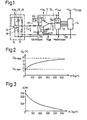
- FIG. 1 shows in a detailed representation a typical circuit for processing the analog air mass signal U H of the hot wire air mass meter for a downstream analog digital converter and FIGS. 2 and 3 the calibration curve of the hot wire air mass meter and the output values of the analog digital converter with the corresponding assigned Air volume values.
- the basic idea of the present invention is to enable an adjustment "over everything" in the fully assembled control unit by using the A / D converter + computer downstream of the input differential amplifier, on which the latter works, as measuring means.
- corresponding air mass signals U H are read in at the input of the differential amplifier, output again via a serial computer interface and preferably immediately compared with the expected digital values for realizing a fully automatic comparison and the comparison, also preferably by laser, to the Hybrid circuit, made.
- the input circuit which processes the analog hot wire air mass meter signal U H (hereinafter abbreviated as HLM signal) for scanning by the computer of the control unit comprises, according to FIG. 1, a differential amplifier 11 connected downstream of the hot wire air mass meter 10;
- the differential amplifier 11 is followed by an A / D converter 12, which converts the analog output voltages U AD supplied to it by the differential amplifier 11 into digital values and, via corresponding data and control line connections 13, feeds it to a downstream computer 14 which, in what This connection does not need to be discussed further, in the usual way receives further operating parameters of an internal combustion engine, for example information about speed, temperature, air temperature, idling, full load and the like.
- receives further operating parameters of an internal combustion engine for example information about speed, temperature, air temperature, idling, full load and the like.
- the duration of fuel injection pulses that are to be supplied to the internal combustion engine Like. And ultimately determined the duration of fuel injection pulses that are to be supplied to the internal combustion engine.
- the actual hot wire air mass meter designated in FIG. 1 consists of the hot wire 15 arranged in the intake pipe of an internal combustion engine in a bridge circuit (Wheatstone bridge) with three further resistors 16, 17 and 18 - the latter can also be a bridging terminal.
- a bridge circuit Woodstone bridge
- an operational amplifier 19 is also provided, the two inputs of which are connected to the bridge diagonal and the output of which feeds the bridge containing the actual hot wire, the output voltage being simultaneous due to the bridging terminal 18 is also present at the other input of the operational amplifier 19.
- the supply voltage for the operational amplifier 19 is designated + U B ; at the output of the hot-wire air mass meter, the HLM voltage U H drops and is replaced by a first R1 stood here on the inverting input of the downstream differential amplifier 11, - which is fed back via a resistor R2 or R2 * (changeable by adjustment) from the output.
- R3 resistors
- R4 adjustable
- the supply voltage for the differential amplifier 11 is again the voltage + U B ; what is useful for the following calculations, two further voltages are defined, namely the voltage drop across resistor R4 with U + and the voltage from the inverting connection to ground with U-; Between the two input connections of the differential amplifier 11, the offset voltage Uoff then results, as is known.
- the control unit ground SG ground is connected to the measuring ground via the hot wire air mass meter 10.
- a resistor R5 of, for example, 1 ohm is preferably connected between the two masses in the control device.
- the A / D converter Since the air wet signal U H represents an absolute value, the A / D converter must also be supplied with a reference voltage Uref.
- the maximum possible voltage offsets (U DIFF ⁇ 100 mV, jUref - U STAB
- the currents of any interference suppression capacitors must be kept away from the measuring mass, which is also important for lambda control.
- the design can therefore be carried out as follows, the stroke U H - U H min of the air volume signal U H to be processed determining the ratio of the resistors R1 and R2:
- Including the calibration curve profile of a special hot-wire air mass meter, as shown in numerical values in FIG. 2, and the output value profile of the analog-digi tal converter when using formulas 6 and 7 provide the calculation bases required for carrying out the adjustment to offset and amplification, the adjustment because the entire chain of input amplifier, analog digital converter, reference voltage and the like. Like. are afflicted with an error, is basically carried out in such a way that at least two analog voltage values, for example for relatively low and for relatively high air mass signals, are applied to the input of the differential amplifier 12 from a high-precision voltage source, and to a serial interface of the control unit 14 expected, corresponding digital values are recorded.
- An elegant adjustment method for the input amplifier 11 therefore consists in using the A / D -Converters 12 with a downstream computer as measuring means, a test program being activated in the computer, which reads in the U H values and outputs them again via a serial interface or, in the case of automatic execution, uses the deviation of the output digital values from the expected values to control the adjustment means Adjustment means are then again preferred laser devices which change the corresponding resistance values on the hybrid circuit, as explained in more detail below.
- the following table shows possible ranges of variation of the air mass flow in an intake pipe of an internal combustion engine in numerical values and on the basis of the calculation that has just been carried out.
- the gain can 1.9 can be selected, ie the last column of the table applies.
- the A / D converter 12 (ADC ⁇ 8 ⁇ 9) is specified from 0 ° to + 70 ° C for a maximum error of + - 1 LSB.
- the offset voltage of the differential amplifier 11 itself has no significant influence on the accuracy, since it is compensated for by adjustment.
- the voltage U ref may have a temperature drift of 60ppm / ° C.
Abstract
Description
Die Erfindung geht aus von einem Abgleichverfahren für einen Hitzdraht-Luftmassenmesser nach der Gattung des Hauptanspruchs sowie einem zur Durchführung des Abgleichverfahrens geeigneten Hitzdraht-Luftmassenmesser nach der Gattung des Anspruchs 4. Die Verwendung von sogenannten Hitzdraht-Luftmassenmessern zur Gewinnung eines Lastsignals bei einer Brennkraftmaschine - in diesem Fall Erfassung des Luftdurchsatzes durch das Ansaugrohr - ist bei elektrischen oder elektronischen Kraftstoffdosiersystemen allgemein bekannt (DE-OS 28 40 793). Es ist in diesem Zusammenhang auch bekannt, den im Ansaugrohr angeordneten Hitzdraht in einer Brückenschaltung mit mindestens zwei weiteren Widerständen anzuordnen und ein entsprechend aufbereitetes, etwa stabilisiertes und verstärktes Ausgangsmeßsignal UH dadurch für eine auf digitaler Basis arbeitende Kraftstoffeinspritzanlage weiter aufzubereiten, daß das Luftmassensignal UH einem nachgeschalteten Analogdigitalwandler und anschließend von diesem demeigentlichen Steuergerät für die Erzeugung von Kraftstoffeinspritzimpulsen zugeführt wird.The invention is based on a calibration method for a hot wire air mass meter according to the preamble of the main claim and a hot wire air mass meter suitable for carrying out the calibration method according to the preamble of
Dabei hat sich als nachteilig ergeben, daß bisher bekannte Eingangsschaltungen für den Hitzdraht-Luftmassenmesser häufig aus einzeln für sich abgeglichenen Komponenten bestanden mit der Folge, daß die jeweiligen Toleranzen sich addierten und eine noch akzeptable Gesamttoleranz daher hochgenaue und entsprechend teure Komponenten erforderlich machte.It has been found to be disadvantageous that previously known input circuits for the hot-wire air mass meter often consisted of individually adjusted components, with the result that the respective tolerances added up and an acceptable overall tolerance therefore made highly accurate and correspondingly expensive components necessary.
Zwar ist es andererseits möglich, auch mit Komponenten zu arbeiten, die innerhalb eines normalen Toleranzbereiches liegen; in diesem Fall ist aber ein mindestens dreifach iterativer Abgleich an mehreren Stellen erforderlich, so daß das Abgleichverfahren wiederum so kostenintensiv ist, und im übrigen entsprechend automatisierungsfeindlich, daß zur Vermeidung dieser Probleme der vorliegenden Erfindung die Aufgabe zugrundeliegt, ein Abgleichverfahren für einen Hitzdraht-Luftmassenmesser sowie einen für die Realisierung dieses Abgleichverfahrens geeigneten Hitzdraht-Luftmassenmesser zu schaffen, bei dem auch unter Einbeziehung des Umstandes, daß ein nichtlinearer Zusammenhang zwischen Luftmassendurchsatz und Luftmassenmessersignal besteht, ein besonders einfacher Abgleich möglich ist, bei dem keine Addition von Einzeltoleranzen auftritt, der die Verwendung von nur wenigen preiswerten Bauteilen ermöglicht und dennoch bei erzielter besonders hoher Präzision nur einige einfache, darüber hinaus noch nichtiterative Abgleiche erfordert.On the other hand, it is possible to work with components that are within a normal tolerance range; in this case, however, an iterative adjustment at least three times is required at several points, so that the adjustment process is again so cost-intensive and, furthermore, correspondingly hostile to automation, that the object of the present invention is to avoid these problems, an adjustment method for a hot-wire air mass meter and to create a hot wire air mass meter suitable for the implementation of this adjustment method, in which also taking into account the fact that a non-linear relationship between Air mass flow rate and air mass meter signal exists, a particularly simple adjustment is possible, in which there is no addition of individual tolerances, which allows the use of only a few inexpensive components and yet, with particularly high precision achieved, only requires a few simple, in addition, non-iterative adjustments.
Das erfindungsgemäße Abgleichverfahren für einen Hitzdraht-Luftmassenmesser sowie der erfindungsgemäße Hitzdraht-Luftmassenmesser lösen diese Aufgabe jeweils mit den kennzeichnenden Merkmalen des Hauptanspruchs bzw. des Anspruchs 4 und haben den Vorteil, daß der Abgleich im fertig zusammengebauten Steuergerät als sogenannter Abgleich "über alles" durchgeführt werden kann, wobei auch ein vollautomatischer Abgleich möglich ist, indem mittels Laserstrahlen auf die Hybridschaltung lediglich Widerstandswerte im Bereich des das Luftmassensignal UH verarbeitenden Eingangsverstärkers zu trimmen- sind. Von besonderem Vorteil ist ferner, daß das erfindungsgemäße Abgleichverfahren ein nichtiteratives Verfahren ist und jede Addition von Einzeltoleranzen vermieden wird. Der Abgleich kann im fertig zusammengebauten Steuergerät erfolgen, wobei den Laser-Führungsmitteln so lange der Differenzwert, also im Grunde die Abgleich-Regelabweichung zugeführt wird, bis bei jedem der zugeführten Analogwerte der "richtige" Digitalwert an einer entsprechenden Schnittstelle des Rechners erscheint. Aktiviert man ein entsprechendes Testprogramm im Rechner, bei dem dann beispielsweise dem Eingang des das Luftmassensignal U zugeführt erhaltenden Verstärkers etwa zwei analoge Signale, beispielsweise eine relativ niedrige UH-Spannung und eine relativ hohe UH-Spannung zugeführt werden, dann kann der Rechner selbst den Abgleich vollautomatisch durchführen, wobei er die Laserführungsmittel so lange ansteuert, wie sich eine Differenz zwischen den zugeführten analogen Spannungswerten und den zu erwartenden digitalen Werten ergibt.The adjustment method according to the invention for a hot-wire air mass meter and the hot-wire air mass meter according to the invention each achieve this object with the characterizing features of the main claim or
Durch die in den Unteransprüchen aufgeführten Maßnahmen sind vorteilhafte Weiterbildungen und Verbesserungen der Erfindung möglich. Besonders vorteilhaft ist der einfache Aufbau des Eingangsverstärkers für das Luftm,assen- signal UH in Form eines Operationsverstärkers mit einer äußeren Beschaltung von lediglich vier Widerständen, von denen dann lediglich zwei durch den Abgleich entsprechend getrimmt werden.Advantageous further developments and improvements of the invention are possible through the measures listed in the subclaims. The simple design of the input amplifier for the air mass signal U H in the form of an operational amplifier with an external circuit of only four resistors, of which only two are then appropriately trimmed by the adjustment, is particularly advantageous.
Ein Ausführungsbeispiel der Erfindung ist in der Zeichnung dargestellt und wird in der nachfolgenden Beschreibung näher erläutert. Es zeigen Fig. 1 in detaillierter Darstellung eine typische Schaltung zur Aufbereitung des analogen Luftmassensignals UH des Hitzdraht-Luftmassenmessers für einen nachgeschalteten Analogdigitalwandler und die Figuren 2 und 3 die Eichkurve des Hitzdraht-Luftmassenmessers sowie die Ausgangswerte des Analogdigitalwandlers mit den entsprechenden zugeordneten Luftmengenwerten.An embodiment of the invention is shown in the drawing and is explained in more detail in the following description. 1 shows in a detailed representation a typical circuit for processing the analog air mass signal U H of the hot wire air mass meter for a downstream analog digital converter and FIGS. 2 and 3 the calibration curve of the hot wire air mass meter and the output values of the analog digital converter with the corresponding assigned Air volume values.
Der Grundgedanke vorliegender Erfindung besteht darin, einen Abgleich "über alles" im fertig zusammengebauten Steuergerät zu ermöglichen, indem der dem EingangsDifferenzverstärker nachgeschaltete A/D-Wandler + Rechner, auf welchen dieser arbeitet, zugleich als Meßmittel verwendet werden. Durch Aktivierung eines entsprechenden Testprogramms im Rechner werden am Eingang des , Differenzverstärkers entsprechende Luftmass ensignale UH eingelesen, über eine serielle Rechnerschnittstelle wieder ausgegeben und vorzugsweise sofort zur Realisierung eines vollautomatischen Abgleichs mit den zu erwartenden Digitalwerten verglichen und der Abgleich, ebenfalls vorzugsweise über Laser auf die Hybridschaltung, vorgenommen.The basic idea of the present invention is to enable an adjustment "over everything" in the fully assembled control unit by using the A / D converter + computer downstream of the input differential amplifier, on which the latter works, as measuring means. By activating a corresponding test program in the computer, corresponding air mass signals U H are read in at the input of the differential amplifier, output again via a serial computer interface and preferably immediately compared with the expected digital values for realizing a fully automatic comparison and the comparison, also preferably by laser, to the Hybrid circuit, made.
Die das analoge Hitzdraht-Luftmassenmessersignal UH (im folgenden als HLM-Signal abgekürzt) zur Abtastung durch den Rechner des Steuergeräts aufbereitende Eingangsschaltung umfaßt entsprechend Fig. 1 einen dem Hitzdraht-Luftmassenmesser 10 nachgeschalteten Differenzverstärker 11; dem Differenzverstärker 11 ist ein A/D-Wandler 12 nachgeschaltet, der die ihm vom Differenzverstärker 11 zugeführten analogen Ausgangsspannungen UAD in digitale Werte umwandelt und über entsprechende Daten und Kontrolleitungsverbindungen 13 einem nachgeschalteten Rechner 14 zuführt, der, worauf in diesem Zusammenhang nicht weiter eingegangen zu werden braucht, in der üblichen Weise noch weitere Betriebsparameter einer Brennkraftmaschine zugeführt erhält, beispielsweise Angaben über Drehzahl, Temperatur, Lufttemperatur, Leerlauf, Vollast u. dgl. und daraus letzten Endes die Dauer von Kraftstoffeinspritzimpulsen bestimmt, die der Brennkraftmaschine zuzuführen sind. Dies gilt jedenfalls dann, -wenn es sich bei der die Ausgangssignale des Hitzdraht-Luftmassenmessers verarbeitenden Schaltung um eine Kraftstoffeinspritzanlage handelt - es versteht sich, daß die erfindungsgemäße Auswerteschaltung mit Hitzdraht-Luftmassenmesser- und das der Erfindung zugrundeliegende Abgleichverfahren bei beliebigen Kraftstoffdosiersystemen angewendet werden können.The input circuit which processes the analog hot wire air mass meter signal U H (hereinafter abbreviated as HLM signal) for scanning by the computer of the control unit comprises, according to FIG. 1, a
Der in Fig. 1 mit 10 bezeichnete eigentliche Hitzdraht-Luftmassenmesser besteht für sich selbst aus dem im Ansaugrohr einer Brennkraftmaschine angeordneten Hitzdraht 15 in einer Brückenschaltung (Wheatstone-Brücke) mit drei weiteren Widerständen 16, 17 und 18 - letzterer kann auch eine Überbrückungsklemme sein. Etwa zur Stabilisierung ist bei dem in Fig. 1 -gezeigten Aufbau des Hitzdraht-Luftmassenmessers noch ein Operationsverstärker 19 vorgesehen, dessen beide Eingänge mit der Brükkendiagonalen verbunden sind und dessen Ausgang die den eigentlichen Hitzdraht enthaltende Brücke speist, wobei aufgrund der Überbrückungsklemme 18 die Ausgangsspannung gleichzeitig auch an dem anderen Eingang des Operationsverstärkers 19 anliegt. Die Speisespannung für den Operationsverstärker 19 ist mit +UB bezeichnet; am Ausgang des Hitzdraht-Luftmassenmessers fällt die HLM-Spannung UH ab und wird über einen ersten Widerstand R1 hier auf den invertierenden Eingang des nachgeschalteten Differenzverstärkers 11 geführt,- der über einen Widerstand R2 bzw. R2* (veränderbar durch Abgleich) vom Ausgang rückgekoppelt ist. Am anderen, nichtinvertierenden Eingang des Differenzverstärkers 11 liegt die Reihenschaltung zweier Widerstände R3 (bzw. R3*, weil durch Abgleich veränderbar) sowie R4. (einstellbar) an; diese Spannungsteilerschaltung wird, ebenso wie der Analogdigitalwandler 12 gespeist von einer genauen Referenzspannung +Uref. Die Speisespannung für den Differenzverstärker 11 ist wiederum die Spannung +UB; dabei sind, was für die nachfolgenden Rechnungen sinnvoll ist, noch zwei weitere Spannungen definiert, nämlich die am Widerstand R4 abfallende Spannung mit U+ und die Spannung vom invertierenden Anschluß gegen Masse mit U-; zwischen den beiden Eingangsanschlüssen des Differenzverstärkers 11 ergibt sich dann noch, wie ja bekannt, die Offset-Spannung Uoff.The actual hot wire air mass meter designated in FIG. 1 consists of the
Die folgenden Ausführungen betreffen sich aus diesen Schaltungsgegebenheiten ergebende Berechnungsmöglichkeiten hauptsächlich. für den Eingangsverstärker, wobei nachfolgend dann auch mit numerischen Werten unter Zugrundelegung bestimmter Schaltungskomponenten und Widerstandsverhältnisse gearbeitet wird. Dies dient zum besseren Verständnis der Erfindung, schränkt diese aber, wie es sich versteht, nicht ein. Hierauf wird sofort hingewiesen. Es sei schließlich noch erwähnt, daß der Differenzverstärker 11 die eine Hälfte eines unter der Bezeichnung 2904 von der Firma National Semiconductors erhältlichen integrierten Bausteins ist; der A/D-Wandler 12 ist unter der Bezeichnung-AD0809 von der Firma National Semiconductors erhältlich, und der Rechner des Steuergeräts trägt die Bezeichnung 8051 und wird von der Firma Intel vertrieben.The following explanations mainly relate to the calculation possibilities resulting from these circuit conditions. for the input amplifier, which is then also worked with numerical values on the basis of certain circuit components and resistance ratios. This serves for a better understanding of the invention, but, as is understood, does not restrict it. This is immediately pointed out. Finally, it should be mentioned that the
Durch die Ankopplung der HLM-MeBmasse mit dem Minusanschluß des Differenzverstärkers 11 und des A/D-Wandlers 12 erübrigt sich ein "echter" Differenzverstärker. Die Steuergerätemasse SG-Masse ist mit der Meßmasse über den Hitzdraht-Luftmassenmesser 10 verbunden. Zur Sicherheit (und Entstörung) ist zwischen den beiden Massen im Steuergerät vorzugsweise noch ein Widerstand R5 von beispielsweise 1 Ohm geschaltet.By coupling the HLM measurement mass with the negative connection of the
Da das Luftnassensignal UH einen Absolutwert darstellt, muß auch der A/D-Wandler mit einer Referenzspannung Uref versorgt werden. Die maximal möglichen Spannungsversätze (UDIFF<100 mV, jUref - USTAB|<0,2 V) werden auf den Daten- bzw. Kontrolleitungen 13 noch ohne weiteres vertragen. Insbesondere sind die Ströme eventueller Entstörkondensatoren von der Meßmasse fernzuhalten, was auch für die Lambdaregelung wichtig ist.Since the air wet signal U H represents an absolute value, the A / D converter must also be supplied with a reference voltage Uref. The maximum possible voltage offsets (U DIFF <100 mV, jUref - U STAB | <0.2 V) are easily tolerated on the data or control lines 13. In particular, the currents of any interference suppression capacitors must be kept away from the measuring mass, which is also important for lambda control.
Berechnet man die Spannungs- und Widerstandsverhältnisse für den Eingangsverstärker, dann gelten die folgenden Gleichungen:
![]()


![]()
Aus den Formeln zu 1., 2., 3., 4. folgt
Für die Bemessung kann man daher wie folgt vorgehen, wobei der zu verarbeitende Hub UH - UH min des Luft- mengensignals UH das Verhältnis der Widerstände R1 und R2 bestimmt:
Der Spannungsteiler R3, R4 ergibt sich dann aus der folgenden Gleichung:
Es liegen nunmehr unter Einbeziehung des Eichkurvenverlaufs eines speziellen Hitzdraht-Luftmassenmessers, wie dies in numerischen Werten in Fig. 2 dargestellt ist, und des Ausgangs-Werteverlaufs des Analog-Digital-Wandlers bei Anwendung der Formeln 6. und 7. die für die Durchführung des Abgleichs auf Offset und Verstärkung erforderlichen Berechnungsgrundlagen vor, wobei der Abgleich, weil die gesamte Kette aus Eingangsverstärker, Analogdigitalwandler, Referenzspannung u. dgl. mit einem Fehler behaftet sind, grundsätzlich so durchgeführt wird, daß an den Eingang des Differenzverstärkers 12 von einer hochpräzisen Spannungsquelle mindestens zwei analoge Spannungswerte etwa für relativ niedrige und für relativ hohe Luftmassensignale, angelegt werden und an einer seriellen Schnittstelle des Steuergeräts 14 die zu erwartenden, entsprechenden Digitalwerte erfaßt werden. Durch Veränderung lediglich der Widerstände R3 und R2 ohne iterative Wiederholung wird dann der Abgleich 'über alles" durchgeführt, der analogtechnisch lediglich durch Widerstandsänderung im Bereich des Eingangsverstärkers 11 realisiert wird. Ein elegantes Abgleichverfahren für den Eingangsverstärker 11 besteht daher in der Verwendung des A/D-Wandlers 12 mit nachgeschaltetem Rechner als Meßmittel, wobei im Rechner ein Testprogramm aktiviert wird, welches die UH-Werte einliest und über eine serielle Schnittstelle wieder ausgibt bzw. bei automatischem Ablauf die Abweichung der ausgegebenen Digitalwerte von den zu erwartenden zur Ansteuerung der Abgleichmittel benutzt. Abgleichmittel sind dann wieder bevorzugt Laser-Einrichtungen die auf der Hybridschaltung, wie im folgenden noch genauer erläutert, die entsprechenden Widerstandswerte verändern.Including the calibration curve profile of a special hot-wire air mass meter, as shown in numerical values in FIG. 2, and the output value profile of the analog-digi tal converter when using formulas 6 and 7 provide the calculation bases required for carrying out the adjustment to offset and amplification, the adjustment because the entire chain of input amplifier, analog digital converter, reference voltage and the like. Like. are afflicted with an error, is basically carried out in such a way that at least two analog voltage values, for example for relatively low and for relatively high air mass signals, are applied to the input of the
7 Zur Durchführung des sogenannten Offsetabgleichs wird davon ausgegangen, daß das die Verstärkung bestimmende Widerstandsverhältnis aus R2/R1 auf den Ausgang dann den geringsten Durchgriff hat, wenn die Ein- undAusgangspins oder Anschlüsse des Operationsverstärkers, also des Eingangsdifferenzverstärkers 11 auf dem gleichen Spannungspegel liegen. Daher wird das Luftmengensignal UH gewählt zu
Jetzt muß man R3* so trimmen, daß der ADW-Wert aus der nachfolgenden Formel 9. erfüllt ist:
Für den Verstärkungsabgleich wird davon ausgegangen, daß für Eingangsspannungen UH nahe UH min und nahe UH max der Durchgriff des Widerstandsverhältnisses R2/R1 am größten ist. In diesen Punkten läßt sich daher jetzt die Verstärkung insoweit problemlos messen und der Widerstand R2* entsprechend zum Abgleich trimmen.For the gain adjustment it is assumed that the penetration of the resistance ratio R2 / R1 is greatest for input voltages U H close to U H min and close to U H max . In these points, the gain can now be easily measured and the resistor R2 * trimmed accordingly.
Die folgenden Ausführungen betreffen noch eine Toleranzbetrachtung der verschiedenen Einflußgrößen, und zwar, wie eingangs schon erwähnt, unter Zugrundelegung numerischer Werte, um eine effektive Abschätzung zu ermöglichen. Diese Ausführungen runden daher die Erfindung ab, schränken diese jedoch nj cht auf die angegebenen Ausführungsformen ein. Betrachtet werden lediglich die wesentlichen Einflußgrößen wie Uref, Uoff und die Genauigkeit des A/D-Wandlers 12.The following explanations relate to a tolerance analysis of the various influencing variables, and, as already mentioned at the beginning, using numerical values in order to enable an effective estimation. These explanations therefore round off the invention, but do not restrict it to the specified embodiments. Only the main influencing factors such as Uref, Uoff and the A /
Zur Genauigkeitsbetrachtung des Analogdigitalwandlers 12 läßt sich die Eichkurve des HLM 4.7 (HJ 63) mit der Funktion m [kg/h] = 13.5 . (UH[V]-1,15)3 annähern.
Bei Uref = 5,0 V entspricht 1 LSB = ![]()
![]()
Für eine Verstärkung des Differenzverstärkers 11 von ![]()

![]()
Es gilt also:
Die folgende Tabelle gibt mögliche Variationsbereiche des Luftmassen dur chflusses in einem Ansaugrohr einer Brennkraftmaschine in numerischen Werten und unter Zugrundelegung der soeben durchgeführten Berechnung an.

Bei einem angenommenen Variationsbereich im Durchfluß von 1 : 100 bzw. 5 kg/h : 500 kg/h kann die Verstärkung ![]()
![]()
Die Offsetspannung des Differenzverstärkers 11 selbst hat keinen signifikanten Einfluß auf die Genauigkeit, da sie per Abgleich kompensiert wird.The offset voltage of the
Der Temperaturgang typischer Operationsverstärker (z.B. LM 29∅4) für die Offsetspannung beträgt etwa 7 µV/°C. über ΔT = 100 °C entsteht dann ein ΔUoff = 0,7 mV. Als Formel 5. mit R2 R1= 1,9 erhält man:The temperature response of typical operational amplifiers (eg LM 29∅4) for the offset voltage is about 7 µV / ° C. A ΔUoff = 0.7 mV then arises above ΔT = 100 ° C. As


Bei der Toleranzbetrachtung bezüglich der Genauigkeit der Referenzspannung Uref folgt aus Gleichung 5. mit Uoff = 0 und R2 R1= 1,9

Die notwendige Änderung der Referenzspannung Uref, um 1 LSB Fehler zu erzeugen, hängt also vom Arbeitspunkt ab (Uref = 5 V):
![]()
![]()
Mit ΔUref = 15 mV beträgt der λ-Fehler über den gesamten Hub etwa Δλ ≤ 1,5 %. Wenn diese Spannungsdrift bei einem Temperaturbereich von O° + 50°C zu realisieren ist, so darf die Spannung Uref eine Temperaturdrift von 60ppm/°C haben.With ΔU ref = 15 mV, the λ error over the entire stroke is approximately Δλ ≤ 1.5%. If this voltage drift can be realized at a temperature range of 0 ° + 50 ° C, the voltage U ref may have a temperature drift of 60ppm / ° C.
Alle in der Beschreibung, den nachfolgenden Ansprüchen und der Zeichnung dargestellten Merkmale können sowohl einzeln als auch in beliebiger Kombination miteinander erfindungswesentlich sein.All features shown in the description, the following claims and the drawing can be essential to the invention both individually and in any combination with one another.
Claims (5)
Applications Claiming Priority (2)
| Application Number | Priority Date | Filing Date | Title |
|---|---|---|---|
| DE3520392 | 1985-06-07 | ||
| DE19853520392 DE3520392A1 (en) | 1985-06-07 | 1985-06-07 | COMPARATIVE METHOD FOR A HOT WIRE AIR MASS METER AND HOT WIRE AIR MASS METER FOR IMPLEMENTING THE METHOD |
Publications (2)
| Publication Number | Publication Date |
|---|---|
| EP0204183A1 true EP0204183A1 (en) | 1986-12-10 |
| EP0204183B1 EP0204183B1 (en) | 1989-05-10 |
Family
ID=6272649
Family Applications (1)
| Application Number | Title | Priority Date | Filing Date |
|---|---|---|---|
| EP86106495A Expired EP0204183B1 (en) | 1985-06-07 | 1986-05-13 | Method for calibrating a hot wire air mass flow meter and hot wire air mass flow meter |
Country Status (3)
| Country | Link |
|---|---|
| EP (1) | EP0204183B1 (en) |
| JP (1) | JPS61284610A (en) |
| DE (2) | DE3520392A1 (en) |
Cited By (4)
| Publication number | Priority date | Publication date | Assignee | Title |
|---|---|---|---|---|
| GB2276725A (en) * | 1993-04-01 | 1994-10-05 | Ford Motor Co | Calibrating a mass air flow sensor |
| EP1014046A1 (en) * | 1996-09-13 | 2000-06-28 | Hitachi, Ltd. | Thermal air flow meter |
| EP1840536A1 (en) * | 2006-03-31 | 2007-10-03 | Sensirion AG | Flow sensor with flow-adaptable analog-digital-converter |
| CN117516671A (en) * | 2024-01-05 | 2024-02-06 | 中国航空油料有限责任公司成都分公司 | Mobile standard device for calibrating flowmeter of aircraft fuelling vehicle |
Families Citing this family (8)
| Publication number | Priority date | Publication date | Assignee | Title |
|---|---|---|---|---|
| KR910002791B1 (en) * | 1987-01-23 | 1991-05-04 | 미쓰비시 뎅끼 가부시기가이샤 | Input processing circuit for air flow sensor |
| DE3742443A1 (en) * | 1987-12-15 | 1989-07-06 | Bosch Gmbh Robert | Circuit arrangement for digitising an analog signal |
| JP2765881B2 (en) * | 1988-11-09 | 1998-06-18 | 三菱電機株式会社 | Intake air amount measurement device for internal combustion engine |
| DE4130512A1 (en) * | 1991-09-13 | 1993-03-18 | Pierburg Gmbh | Signal gain and offset compensation appts. for electrical measurement signals, esp. for engine induction - uses operational amplifier with variable reference voltage and variable resistance to earth |
| US5504681A (en) * | 1994-06-29 | 1996-04-02 | Ford Motor Company | Mass air flow sensor calibration |
| JP2929950B2 (en) * | 1994-10-21 | 1999-08-03 | 株式会社日立製作所 | Control device for internal combustion engine |
| KR100406898B1 (en) * | 1995-10-20 | 2004-05-20 | 가부시키 가이샤 히다치 카 엔지니어링 | Control Method and Device of Internal Combustion Engine for Vehicle |
| CN114624466B (en) * | 2022-05-17 | 2022-07-12 | 西南石油大学 | Hot wire anemometer-based testing device and testing method |
Citations (2)
| Publication number | Priority date | Publication date | Assignee | Title |
|---|---|---|---|---|
| US4264961A (en) * | 1978-06-02 | 1981-04-28 | Hitachi, Ltd. | Air flow rate measuring apparatus |
| GB2107883A (en) * | 1981-10-08 | 1983-05-05 | Jaeger | Digital hot-wire liquid level detecting apparatus |
-
1985
- 1985-06-07 DE DE19853520392 patent/DE3520392A1/en not_active Withdrawn
-
1986
- 1986-05-13 DE DE8686106495T patent/DE3663306D1/en not_active Expired
- 1986-05-13 EP EP86106495A patent/EP0204183B1/en not_active Expired
- 1986-05-20 JP JP61113815A patent/JPS61284610A/en active Pending
Patent Citations (2)
| Publication number | Priority date | Publication date | Assignee | Title |
|---|---|---|---|---|
| US4264961A (en) * | 1978-06-02 | 1981-04-28 | Hitachi, Ltd. | Air flow rate measuring apparatus |
| GB2107883A (en) * | 1981-10-08 | 1983-05-05 | Jaeger | Digital hot-wire liquid level detecting apparatus |
Cited By (11)
| Publication number | Priority date | Publication date | Assignee | Title |
|---|---|---|---|---|
| GB2276725A (en) * | 1993-04-01 | 1994-10-05 | Ford Motor Co | Calibrating a mass air flow sensor |
| US5493892A (en) * | 1993-04-01 | 1996-02-27 | Ford Motor Company | Method for calibrating the time response of a mass air flow sensor by laser trimming selected resistors and without an air flow |
| GB2276725B (en) * | 1993-04-01 | 1996-10-02 | Ford Motor Co | Calibrating a mass air flow sensor |
| EP1014046A1 (en) * | 1996-09-13 | 2000-06-28 | Hitachi, Ltd. | Thermal air flow meter |
| EP1014046A4 (en) * | 1996-09-13 | 2002-05-29 | Hitachi Ltd | Thermal air flow meter |
| EP1840536A1 (en) * | 2006-03-31 | 2007-10-03 | Sensirion AG | Flow sensor with flow-adaptable analog-digital-converter |
| JP2007282218A (en) * | 2006-03-31 | 2007-10-25 | Sensirion Ag | Flow sensor equipped with flow adaption available analog-to-digital converter |
| US7490511B2 (en) | 2006-03-31 | 2009-02-17 | Sensirion Ag | Flow sensor with flow-adaptable analog-digital-converter |
| CN101046401B (en) * | 2006-03-31 | 2011-08-24 | 森斯瑞控股股份公司 | Flow sensor with flow-adaptable analog-digital-converter |
| CN117516671A (en) * | 2024-01-05 | 2024-02-06 | 中国航空油料有限责任公司成都分公司 | Mobile standard device for calibrating flowmeter of aircraft fuelling vehicle |
| CN117516671B (en) * | 2024-01-05 | 2024-04-09 | 中国航空油料有限责任公司成都分公司 | Mobile standard device for calibrating flowmeter of aircraft fuelling vehicle |
Also Published As
| Publication number | Publication date |
|---|---|
| JPS61284610A (en) | 1986-12-15 |
| DE3663306D1 (en) | 1989-06-15 |
| EP0204183B1 (en) | 1989-05-10 |
| DE3520392A1 (en) | 1986-12-11 |
Similar Documents
| Publication | Publication Date | Title |
|---|---|---|
| DE2917237C2 (en) | ||
| EP0169414A2 (en) | Method for the temperature compensation and measuring circuit for this method | |
| EP0221251B1 (en) | Fault-compensating method for sensing elements with non-linear characteristics, and device for performing it | |
| EP1001248A2 (en) | Method for offset calibrating a magneto-resistive angle sensor | |
| EP0204183B1 (en) | Method for calibrating a hot wire air mass flow meter and hot wire air mass flow meter | |
| DE3151743A1 (en) | MEASURING DEVICE WITH MULTIPLE ELEMENT PROBE | |
| EP0173833A2 (en) | Circuit and process to measure and to digitize a resistor | |
| EP0101956B1 (en) | Resistance thermometer | |
| WO1987006339A1 (en) | Circuitry for measuring mechanical deformation, specially under pressure | |
| DE3309404C2 (en) | ||
| DE2518890A1 (en) | LINEARIZING DEVICE | |
| DE3831659A1 (en) | SWITCHING ON OAK METER | |
| DE19837440C2 (en) | Analog / digital converter device and control device for a gradient amplifier | |
| EP1156299B1 (en) | Measuring transducer for potentiometric position sensors and method for adjusting the parameters | |
| DE1951220A1 (en) | Method and device for the analysis of samples | |
| DE1914596A1 (en) | Device for measuring by determining the temperature of a filament heated by the Joule effect | |
| DE2710782C2 (en) | Device for measuring temperature differences | |
| DE3617936C2 (en) | ||
| DE2460079C3 (en) | Method for determining the position of the wiper of a potentiometer and circuit arrangement for carrying out the method | |
| DE3313043C2 (en) | ||
| DE2203927A1 (en) | ||
| EP1132794B1 (en) | Method to derive a temperature independent voltage reference and a circuit to derive such a voltage reference | |
| DE4013089A1 (en) | IC engine control input voltage error corrected measurement - deriving accurate value of auxiliary parameter and replacement of reference parameter with derived digital ratio | |
| DE2526027A1 (en) | Refrigerator plant temp. difference monitor - provides multipoint direct measurement of temp. differences as current differences to accuracy of tenth of degree C | |
| DE3519390C2 (en) |
Legal Events
| Date | Code | Title | Description |
|---|---|---|---|
| PUAI | Public reference made under article 153(3) epc to a published international application that has entered the european phase |
Free format text: ORIGINAL CODE: 0009012 |
|
| AK | Designated contracting states |
Kind code of ref document: A1 Designated state(s): DE FR GB IT SE |
|
| 17P | Request for examination filed |
Effective date: 19870226 |
|
| 17Q | First examination report despatched |
Effective date: 19880915 |
|
| GRAA | (expected) grant |
Free format text: ORIGINAL CODE: 0009210 |
|
| AK | Designated contracting states |
Kind code of ref document: B1 Designated state(s): DE FR GB IT SE |
|
| PGFP | Annual fee paid to national office [announced via postgrant information from national office to epo] |
Ref country code: FR Payment date: 19890614 Year of fee payment: 4 |
|
| REF | Corresponds to: |
Ref document number: 3663306 Country of ref document: DE Date of ref document: 19890615 |
|
| ET | Fr: translation filed | ||
| GBT | Gb: translation of ep patent filed (gb section 77(6)(a)/1977) | ||
| PGFP | Annual fee paid to national office [announced via postgrant information from national office to epo] |
Ref country code: SE Payment date: 19890717 Year of fee payment: 4 |
|
| PGFP | Annual fee paid to national office [announced via postgrant information from national office to epo] |
Ref country code: DE Payment date: 19890727 Year of fee payment: 4 |
|
| ITF | It: translation for a ep patent filed |
Owner name: STUDIO JAUMANN |
|
| PLBE | No opposition filed within time limit |
Free format text: ORIGINAL CODE: 0009261 |
|
| STAA | Information on the status of an ep patent application or granted ep patent |
Free format text: STATUS: NO OPPOSITION FILED WITHIN TIME LIMIT |
|
| 26N | No opposition filed | ||
| PG25 | Lapsed in a contracting state [announced via postgrant information from national office to epo] |
Ref country code: GB Effective date: 19900513 |
|
| PG25 | Lapsed in a contracting state [announced via postgrant information from national office to epo] |
Ref country code: SE Effective date: 19900514 |
|
| ITTA | It: last paid annual fee | ||
| GBPC | Gb: european patent ceased through non-payment of renewal fee | ||
| PG25 | Lapsed in a contracting state [announced via postgrant information from national office to epo] |
Ref country code: FR Effective date: 19910131 |
|
| PG25 | Lapsed in a contracting state [announced via postgrant information from national office to epo] |
Ref country code: DE Effective date: 19910201 |
|
| REG | Reference to a national code |
Ref country code: FR Ref legal event code: ST |
|
| EUG | Se: european patent has lapsed |
Ref document number: 86106495.4 Effective date: 19910115 |
|
| PG25 | Lapsed in a contracting state [announced via postgrant information from national office to epo] |
Ref country code: IT Free format text: LAPSE BECAUSE OF NON-PAYMENT OF DUE FEES;WARNING: LAPSES OF ITALIAN PATENTS WITH EFFECTIVE DATE BEFORE 2007 MAY HAVE OCCURRED AT ANY TIME BEFORE 2007. THE CORRECT EFFECTIVE DATE MAY BE DIFFERENT FROM THE ONE RECORDED. Effective date: 20050513 |