EP0204089A2 - Method to create a three-dimensional model - Google Patents
Method to create a three-dimensional model Download PDFInfo
- Publication number
- EP0204089A2 EP0204089A2 EP86103724A EP86103724A EP0204089A2 EP 0204089 A2 EP0204089 A2 EP 0204089A2 EP 86103724 A EP86103724 A EP 86103724A EP 86103724 A EP86103724 A EP 86103724A EP 0204089 A2 EP0204089 A2 EP 0204089A2
- Authority
- EP
- European Patent Office
- Prior art keywords
- partial
- model
- computer
- workpiece
- machining tool
- Prior art date
- Legal status (The legal status is an assumption and is not a legal conclusion. Google has not performed a legal analysis and makes no representation as to the accuracy of the status listed.)
- Granted
Links
Images

Classifications
-
- G—PHYSICS
- G05—CONTROLLING; REGULATING
- G05B—CONTROL OR REGULATING SYSTEMS IN GENERAL; FUNCTIONAL ELEMENTS OF SUCH SYSTEMS; MONITORING OR TESTING ARRANGEMENTS FOR SUCH SYSTEMS OR ELEMENTS
- G05B19/00—Programme-control systems
- G05B19/02—Programme-control systems electric
- G05B19/42—Recording and playback systems, i.e. in which the programme is recorded from a cycle of operations, e.g. the cycle of operations being manually controlled, after which this record is played back on the same machine
- G05B19/4202—Recording and playback systems, i.e. in which the programme is recorded from a cycle of operations, e.g. the cycle of operations being manually controlled, after which this record is played back on the same machine preparation of the programme medium using a drawing, a model
- G05B19/4207—Recording and playback systems, i.e. in which the programme is recorded from a cycle of operations, e.g. the cycle of operations being manually controlled, after which this record is played back on the same machine preparation of the programme medium using a drawing, a model in which a model is traced or scanned and corresponding data recorded
-
- A—HUMAN NECESSITIES
- A61—MEDICAL OR VETERINARY SCIENCE; HYGIENE
- A61F—FILTERS IMPLANTABLE INTO BLOOD VESSELS; PROSTHESES; DEVICES PROVIDING PATENCY TO, OR PREVENTING COLLAPSING OF, TUBULAR STRUCTURES OF THE BODY, e.g. STENTS; ORTHOPAEDIC, NURSING OR CONTRACEPTIVE DEVICES; FOMENTATION; TREATMENT OR PROTECTION OF EYES OR EARS; BANDAGES, DRESSINGS OR ABSORBENT PADS; FIRST-AID KITS
- A61F2/00—Filters implantable into blood vessels; Prostheses, i.e. artificial substitutes or replacements for parts of the body; Appliances for connecting them with the body; Devices providing patency to, or preventing collapsing of, tubular structures of the body, e.g. stents
- A61F2/02—Prostheses implantable into the body
- A61F2/30—Joints
- A61F2/3094—Designing or manufacturing processes
- A61F2/30942—Designing or manufacturing processes for designing or making customized prostheses, e.g. using templates, CT or NMR scans, finite-element analysis or CAD-CAM techniques
-
- A—HUMAN NECESSITIES
- A61—MEDICAL OR VETERINARY SCIENCE; HYGIENE
- A61F—FILTERS IMPLANTABLE INTO BLOOD VESSELS; PROSTHESES; DEVICES PROVIDING PATENCY TO, OR PREVENTING COLLAPSING OF, TUBULAR STRUCTURES OF THE BODY, e.g. STENTS; ORTHOPAEDIC, NURSING OR CONTRACEPTIVE DEVICES; FOMENTATION; TREATMENT OR PROTECTION OF EYES OR EARS; BANDAGES, DRESSINGS OR ABSORBENT PADS; FIRST-AID KITS
- A61F2/00—Filters implantable into blood vessels; Prostheses, i.e. artificial substitutes or replacements for parts of the body; Appliances for connecting them with the body; Devices providing patency to, or preventing collapsing of, tubular structures of the body, e.g. stents
- A61F2/02—Prostheses implantable into the body
- A61F2/28—Bones
- A61F2002/2825—Femur
-
- A—HUMAN NECESSITIES
- A61—MEDICAL OR VETERINARY SCIENCE; HYGIENE
- A61F—FILTERS IMPLANTABLE INTO BLOOD VESSELS; PROSTHESES; DEVICES PROVIDING PATENCY TO, OR PREVENTING COLLAPSING OF, TUBULAR STRUCTURES OF THE BODY, e.g. STENTS; ORTHOPAEDIC, NURSING OR CONTRACEPTIVE DEVICES; FOMENTATION; TREATMENT OR PROTECTION OF EYES OR EARS; BANDAGES, DRESSINGS OR ABSORBENT PADS; FIRST-AID KITS
- A61F2/00—Filters implantable into blood vessels; Prostheses, i.e. artificial substitutes or replacements for parts of the body; Appliances for connecting them with the body; Devices providing patency to, or preventing collapsing of, tubular structures of the body, e.g. stents
- A61F2/02—Prostheses implantable into the body
- A61F2/30—Joints
- A61F2/3094—Designing or manufacturing processes
- A61F2/30942—Designing or manufacturing processes for designing or making customized prostheses, e.g. using templates, CT or NMR scans, finite-element analysis or CAD-CAM techniques
- A61F2002/30948—Designing or manufacturing processes for designing or making customized prostheses, e.g. using templates, CT or NMR scans, finite-element analysis or CAD-CAM techniques using computerized tomography, i.e. CT scans
-
- A—HUMAN NECESSITIES
- A61—MEDICAL OR VETERINARY SCIENCE; HYGIENE
- A61F—FILTERS IMPLANTABLE INTO BLOOD VESSELS; PROSTHESES; DEVICES PROVIDING PATENCY TO, OR PREVENTING COLLAPSING OF, TUBULAR STRUCTURES OF THE BODY, e.g. STENTS; ORTHOPAEDIC, NURSING OR CONTRACEPTIVE DEVICES; FOMENTATION; TREATMENT OR PROTECTION OF EYES OR EARS; BANDAGES, DRESSINGS OR ABSORBENT PADS; FIRST-AID KITS
- A61F2/00—Filters implantable into blood vessels; Prostheses, i.e. artificial substitutes or replacements for parts of the body; Appliances for connecting them with the body; Devices providing patency to, or preventing collapsing of, tubular structures of the body, e.g. stents
- A61F2/02—Prostheses implantable into the body
- A61F2/30—Joints
- A61F2/3094—Designing or manufacturing processes
- A61F2/30942—Designing or manufacturing processes for designing or making customized prostheses, e.g. using templates, CT or NMR scans, finite-element analysis or CAD-CAM techniques
- A61F2002/30957—Designing or manufacturing processes for designing or making customized prostheses, e.g. using templates, CT or NMR scans, finite-element analysis or CAD-CAM techniques using a positive or a negative model, e.g. moulds
-
- G—PHYSICS
- G05—CONTROLLING; REGULATING
- G05B—CONTROL OR REGULATING SYSTEMS IN GENERAL; FUNCTIONAL ELEMENTS OF SUCH SYSTEMS; MONITORING OR TESTING ARRANGEMENTS FOR SUCH SYSTEMS OR ELEMENTS
- G05B2219/00—Program-control systems
- G05B2219/30—Nc systems
- G05B2219/35—Nc in input of data, input till input file format
- G05B2219/35287—Verify, check program by drawing, display part, testpiece
-
- G—PHYSICS
- G05—CONTROLLING; REGULATING
- G05B—CONTROL OR REGULATING SYSTEMS IN GENERAL; FUNCTIONAL ELEMENTS OF SUCH SYSTEMS; MONITORING OR TESTING ARRANGEMENTS FOR SUCH SYSTEMS OR ELEMENTS
- G05B2219/00—Program-control systems
- G05B2219/30—Nc systems
- G05B2219/45—Nc applications
- G05B2219/45166—Tomography
-
- G—PHYSICS
- G05—CONTROLLING; REGULATING
- G05B—CONTROL OR REGULATING SYSTEMS IN GENERAL; FUNCTIONAL ELEMENTS OF SUCH SYSTEMS; MONITORING OR TESTING ARRANGEMENTS FOR SUCH SYSTEMS OR ELEMENTS
- G05B2219/00—Program-control systems
- G05B2219/30—Nc systems
- G05B2219/45—Nc applications
- G05B2219/45172—Prosthesis
-
- G—PHYSICS
- G05—CONTROLLING; REGULATING
- G05B—CONTROL OR REGULATING SYSTEMS IN GENERAL; FUNCTIONAL ELEMENTS OF SUCH SYSTEMS; MONITORING OR TESTING ARRANGEMENTS FOR SUCH SYSTEMS OR ELEMENTS
- G05B2219/00—Program-control systems
- G05B2219/30—Nc systems
- G05B2219/49—Nc machine tool, till multiple
- G05B2219/49007—Making, forming 3-D object, model, surface
-
- G—PHYSICS
- G05—CONTROLLING; REGULATING
- G05B—CONTROL OR REGULATING SYSTEMS IN GENERAL; FUNCTIONAL ELEMENTS OF SUCH SYSTEMS; MONITORING OR TESTING ARRANGEMENTS FOR SUCH SYSTEMS OR ELEMENTS
- G05B2219/00—Program-control systems
- G05B2219/30—Nc systems
- G05B2219/49—Nc machine tool, till multiple
- G05B2219/49008—Making 3-D object with model in computer memory
-
- G—PHYSICS
- G05—CONTROLLING; REGULATING
- G05B—CONTROL OR REGULATING SYSTEMS IN GENERAL; FUNCTIONAL ELEMENTS OF SUCH SYSTEMS; MONITORING OR TESTING ARRANGEMENTS FOR SUCH SYSTEMS OR ELEMENTS
- G05B2219/00—Program-control systems
- G05B2219/30—Nc systems
- G05B2219/49—Nc machine tool, till multiple
- G05B2219/49011—Machine 2-D slices, build 3-D model, laminated object manufacturing LOM
Definitions
- the invention relates to a method for producing a spatial model of body parts with the aid of computer tomographic partial sections of these body parts, which are placed through the body part in a predetermined sequence and the limits of which are transferred to a model material.
- X-ray examinations in two planes, distance, target and slice images are only able to obtain a two-dimensional idea of an expected field of operation.
- the image obtained has to be corrected with an often unknown correction factor in order to obtain an idea of the true size ratios.
- This correction factor can very often only be determined on the basis of empirical values and therefore remains uncertain.
- a preoperative model construction gives a precise and true-to-scale picture of the expected operating field and thus reliable information about how the operation can be carried out.
- this model had a stair-shaped boundary surface, which, however, could be leveled by lifting off the individual steps in the sense of knowledge of the body part to be imaged.
- This model building requires a good spatial imagination and a high degree of manual skill.
- the object of the present invention is therefore to improve the method of the type mentioned in the introduction in such a way that it can be used for the rapid and inexpensive production of very precise models.
- This object is achieved in that the limits of the computed tomographic partial sections are electronically converted into spatial coordinates, according to which at least one processing tool is controlled for the purpose of processing the module material.
- the partial computed tomography sections can be optimally evaluated.
- a conversion of these partial cuts into a corresponding image of the partial cut can be spared since the coordinates of the delimitation points can be converted directly into electrical impulses that serve to control the machining tool.
- the outline of this partial section can be circumnavigated very precisely and can be electronically determined in this way.
- the electrical impulses obtained with this electronic setting can be used directly as control signals for controlling the machining tool.
- the information about the extension of the model in the three directions of the spatial coordinate system and in the direction of an axis of rotation results from the determination of a reference point, with respect to which the model on the one hand and the body part to be imaged on the other hand are to be brought into agreement.
- the machining tool is guided along imaginary planes, which correspond in their position to a respective partial section, along a block of the model material that is suitable for producing the model.
- the model is produced directly from a block, within which only imaginary planes run in the area of the computed tomographic partial sections. Depending on the distance between two adjacent partial cuts, this model also creates a more or less step-wise surface, which can however be leveled as part of a finishing process. This fine machining takes place with the help of an interpolation of coordinates which delimit adjacent planes.
- planes of the model are cut out of plates of the model material with the processing tool and the individual planes are combined to form the model.
- This method corresponds very largely to that of obtaining coordinates.
- the model to be created creates plate levels that correspond to those of the partial cuts.
- the desired model is created by joining adjacent panels.
- the thickness of the plates corresponds to the distance between two adjacent partial cuts.
- the step-like surface, which is also produced in this way of production, is leveled in a separate operation, which can be controlled either manually or by machine.
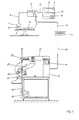
- the method according to the invention is expediently carried out using a system which essentially consists of a computer tomograph 1, a computer 2, a monitor 3, an operating console 4 and a processing machine 5.
- the computer tomograph 1 is connected to the computer 2 via a line 6 the electrical pulses recorded by the computer tomograph 1 are fed into the computer 2.
- These electrical impulses correspond to boundary lines of a body part 7, onto which the computer tomograph 1 with its recording unit 8 is directed.
- This body part 7 can, for example, be a femur of a human being 10o, which lies on a treatment table 11 in the area of influence of the receiving unit 8.
- the electrical pulses fed into the computer 2 via the line 6 are stored, for example in a storage unit of the computer 2, on a magnetic disk or a magnetic tape. From this storage unit, a partial section 12 made by the computer tomograph 1 through the body part 7 can be imaged on the monitor 3.
- This monitor 3 can be connected to the computer 2 in the dialog system, so that the boundary lines 9 of the partial section 12 can be avoided by a cursor.
- the cursor 13 is controlled by the control panel 4, which is connected to the computer 2 via a connecting line 14. This is connected to the monitor 3 via a connecting line 15.
- control panel 4 is connected to the processing machine 5 via a further connecting line 16.
- This processing machine 5 is controlled according to the partial section 12 shown on the monitor 3.
- the processing machine has stepper motors 17, 18 for movements in the Y direction on the one hand and in the Z direction on the other.
- Another stepper motor for movements of the slide in the X direction is present, but is not shown in the drawing.
- a further drive for rotational movements is provided, but is also not shown.
- a processing tool 19 is guided in the processing machine 5 at the front end 20 of a support arm 21.
- This machining tool 7 can be, for example, a wire, a pin or a loop, each of which is heated to a temperature of, for example, 180 ° C. In this heated state, it is capable of separatingly processing a plastic consisting of plastic, for example styrofoam. However, it is also possible to machine other plastics, for example with a milling cutter 22.
- a workpiece 23 is fastened over a workpiece plate 24 to extension arms 25 via clamping plates, not shown.
- the extension arm 25 guides the workpiece 23 connected to it past the machining tool 19. It is controlled by the stepper motors 17, 18 in the Y and Z directions. Control in the X direction as well as with respect to the rotation is carried out by separate motors.
- the processing machine is controlled in accordance with boundary lines 9 of the partial cuts 12. These boundary lines 9 can be bypassed using the cursor. At Umfah Ren of the boundary lines 9, electrical pulses are generated which are used to control the processing machine 5. In this way, the workpiece 23 is machined in accordance with the desired model for each partial cut 12.
- the boundary lines 9 of the respective partial section 12 can be traced not only manually with the help of the cursor, but also with the aid of a contour determination program to be entered into the computer.
- each sub-layer has the thickness of a sheet of the selected plastic.
- a partial layer 26 is worked out from this plate in accordance with the partial cut 12.
- the thickness of the partial layer 26 corresponds to the distance between two adjacent partial cuts 12.
- the partial layers 26 that are created in this way are combined to form a model in the order in which they were created.
- This model has step-shaped gradations 27 on its outer surface. These can be leveled in a subsequent operation as part of a finishing process, so that a model with smooth surfaces is subsequently created.
- Such fine machining must also be carried out when the workpiece 23 is machined in its entirety, since even with this machining method 23 step-shaped gradations 27 arise on the surface of the workpiece, which correspond to the sanding of the partial cuts 12.
Abstract
Description
Die Erfindung betrifft ein Verfahren zur Herstellung eines räumlichen Modells von Körperteilen mit Hilfe computertomografischer Teilschnitte dieser Körperteile, die in einer vorgegebenen Reihenfolge durch das Körperteil gelegt werden und deren Begrenzungen auf einen Modellwerkstoff übertragen werden.The invention relates to a method for producing a spatial model of body parts with the aid of computer tomographic partial sections of these body parts, which are placed through the body part in a predetermined sequence and the limits of which are transferred to a model material.
Die Darstellung von Körperteilen, namentlich innerhalb des menschlichen Körpers liegender Körperteile ist ein für die Weiterentwicklung der Operationstechnik gravierendes Problem. Dieses ergibt sich daraus, daß gerade bei komplizierten Operationen der Chirurg sich ein möglichst umfassendes Bild von dem geschädigten Körperteil machen muß, bevor er die Durchführung der Operation im einzelnen planen kann. Für die Durchführung ist nicht nur die genaue Lage des Krankheitsherdes an dem zu operierenden Körperteil wichtig, sondern möglicherweise auch die Herstellung eines platzhaltenden Modells, das zu einem späteren Zeitpunkt in einer nachfolgenden Operation wieder entfernt und durch eine Endoprothese ersetzt werden kann. Die genaue Kenntnis der räumlichen Abmaße eines von einer Operation betroffenen Körperteils erleichtet die Operationsplanung nicht nur bei Knochenoperafionen, sondern auch bei Eingriffen, die an inneren Organen notwendig werden.The representation of body parts, especially body parts lying within the human body, is a serious problem for the further development of the surgical technique. This results from the fact that, particularly in the case of complicated operations, the surgeon must get as comprehensive a picture as possible of the damaged part of the body before he can plan the operation in detail. For the implementation, not only is the exact location of the focus of the disease on the part of the body to be operated on important, but possibly also the production of a space-saving model, which can be removed at a later time in a subsequent operation and replaced by an endoprosthesis. The precise knowledge of the spatial dimensions of a part of the body affected by an operation makes it easier to plan the operation not only for bone operations, but also for operations that are necessary on internal organs.
Röntgenuntersuchungen in zwei Ebenen, Abstands-, Ziel-und Schichtaufnahmen sind lediglich in der Lage, eine zweidimensionale Vorstellung von einem zu erwartenden Operationsfeld zu erlangen. Außerdem muß bei derartigen zweidimensionalen Darstellungen mit einem oft nicht bekannten Korrekturfaktor das erlangte Bild korrigiert werden, um eine Vorstellung von den wahren Größenverhättnissen zu erhalten. Dieser Korrekturfaktor kann sehr häufig nur aufgrund von Erfahrungswerten festgelegt werden und bleibt daher unsicher. Demgegenüber vermittelt ein präoperativer Modellbau ein genaues und maßstabgerechtes Bild des zu erwartenden Operationsfeldes und damit sichere Angaben über die Art, wie die Operation durchgeführt werden kann.X-ray examinations in two planes, distance, target and slice images are only able to obtain a two-dimensional idea of an expected field of operation. In addition, in the case of such two-dimensional representations, the image obtained has to be corrected with an often unknown correction factor in order to obtain an idea of the true size ratios. This correction factor can very often only be determined on the basis of empirical values and therefore remains uncertain. In contrast, a preoperative model construction gives a precise and true-to-scale picture of the expected operating field and thus reliable information about how the operation can be carried out.
Diese Modelle wurden bisher jedoch im wesentlichen manuell gebaut. Die Angaben über die Abmaße und genaue Gestaltung des Körperteils, zu dem das Modell zu erstellen war, wurden mit Hilfe der Röntgentechnik gewonnen. Sowohl die Angaben über die Abmaße des Körperteils als auch diejenigen über dessen Gestaltung entsprachen jedoch nicht den notwendigen Genauigkeitsvorstellungen. Diese wurden erst erfüllt, als die Ausgangsdaten mit Hilfe von Computertomogrammen gewonnen werden konnten. Mit diesen wurden Teilschnitte durch das darzustellende Körperteil gelegt. Diese Teilschnitte wurden auf Platten eines Modellbaustoffes übertragen. Aus diesen Platten wurden Modelle der jeweiligen Teilschnitte hergestellt. Die einzelnen Teilschnitte wurden zu einem Modell des abzubildenden Körperteils zusammengefügt. Je nach Dicke der Platten besaß dieses Modell eine treppenförmige Begrenzungsfläche, die jedoch im Sinne der Kenntnis des abzubildenden Körperteils durch Abheben der einzelnen Treppenstufen eingeebnet werden konnte. Dieser Modellbau erfordert ein gutes räumliches Vorstellungsvermögen und ein hohes Maß an handwerklichem Geschick.However, these models have so far been built essentially manually. The information about the dimensions and exact design of the body part for which the model was to be created was obtained with the aid of X-ray technology. However, the information about the dimensions of the body part as well as that about its design did not correspond to the necessary ideas of accuracy. These were only met when the initial data could be obtained with the help of computer tomograms. With these, partial sections were made through the body part to be displayed. These partial cuts were transferred to panels of a model building material. Models of the respective partial cuts were made from these plates. The individual partial sections were combined into a model of the body part to be imaged. Depending on the thickness of the slabs, this model had a stair-shaped boundary surface, which, however, could be leveled by lifting off the individual steps in the sense of knowledge of the body part to be imaged. This model building requires a good spatial imagination and a high degree of manual skill.
Aufgabe der vorliegenden Erfindung ist es daher, das Verfahren der einleitend genannten Art so zu verbessern, daß es zur schnellen und kostengünstigen Herstellung sehr genauer Modelle benutzt werden kann.The object of the present invention is therefore to improve the method of the type mentioned in the introduction in such a way that it can be used for the rapid and inexpensive production of very precise models.
Diese Aufgabe wird erfindungsgemäß dadurch gelöst, daß die Begrenzungen der computertomografischen Teilschnitte in räumliche Koordinaten elektronisch umgesetzt werden, nach denen mindestens ein Bearbeitungswerkzeug zum Zwecke der Bearbeitung des Modsllwerkstoffes gesteuert wird.This object is achieved in that the limits of the computed tomographic partial sections are electronically converted into spatial coordinates, according to which at least one processing tool is controlled for the purpose of processing the module material.
Mit diesem Vertahren können die computertomografischen Teilschnitte optimal ausgewertet werden. Eine Umsetzung dieser Teilschnitte in ein entsprechendes Bild des Teilschnittes kann erspart werden, da die Koordinaten der Begrenzungspunkte unmittelbar in elektrische Impulse umgesetzt werden können, die der Steuerung des Bearbeitungswerkzeuges dienen. Aber auch wenn der einzelne Teilschnitt auf einem Monitor abgebildet werden muß, so kann dieser Teilschnitt in seinen Umrissen sehr genau umfahren und auf diese Weise elektronisch festgelegt werden. Die bei dieser elektronischen Festlegung erhaltenen elektrischen Impulse können unmittelbar als Steuersignale zur Steuerung des Bearbeitungswerkzeuges eingesetzt werden. Dabei ergeben sich die Angaben über die Erstreckung des Modells in die drei Richtungen des räumlichen Koordinatensystems und in Richtung einer Rotationsachse aus der Festlegung eines Bezugspunktes, hinsichtlich dessen das Modell einerseits und das abzubildende Körperteil andererseits in Übereinstimmung zu bringen sind.With this procedure, the partial computed tomography sections can be optimally evaluated. A conversion of these partial cuts into a corresponding image of the partial cut can be spared since the coordinates of the delimitation points can be converted directly into electrical impulses that serve to control the machining tool. But even if the individual partial section has to be displayed on a monitor, the outline of this partial section can be circumnavigated very precisely and can be electronically determined in this way. The electrical impulses obtained with this electronic setting can be used directly as control signals for controlling the machining tool. The information about the extension of the model in the three directions of the spatial coordinate system and in the direction of an axis of rotation results from the determination of a reference point, with respect to which the model on the one hand and the body part to be imaged on the other hand are to be brought into agreement.
Gemäß einer bevorzugten Ausführungsform der Erfindung wird das Bearbeitungswerkzeug auf gedachten Ebenen, die in ihrer Lage einem jeweiligen Teilschnitt entsprechen, an einem zur Herstellung des Modells geeigneten Block des Modellwerkstoffes entlanggeführt. Bei dieser Ausführungsform des erfindungsgemäßen Verfahrens wird das Modell unmittelbar aus einem Block hergestellt, innerhalb dessen lediglich gedachte Ebenen im Bereich der computertomografischen Teil schnitte verlaufen. Je nach der Entfernung, die zwischen zwei benachbarten Teilschnitten liegen, entsteht auch bei diesem Modell eine mehr oder minder in Stufen verlaufende Oberfläche, die jedoch im Rahmen einer Feinbearbeitung eingeebnet werden kann. Diese Feinbearbeitung erfolgt mit Hilfe einer Interpolation von Koordinaten, die einander benachbarte Ebenen begrenzen.According to a preferred embodiment of the invention, the machining tool is guided along imaginary planes, which correspond in their position to a respective partial section, along a block of the model material that is suitable for producing the model. At this Embodiment of the method according to the invention, the model is produced directly from a block, within which only imaginary planes run in the area of the computed tomographic partial sections. Depending on the distance between two adjacent partial cuts, this model also creates a more or less step-wise surface, which can however be leveled as part of a finishing process. This fine machining takes place with the help of an interpolation of coordinates which delimit adjacent planes.
Gemäß einer weiteren bevorzugten Ausführungsform der Erfindung werden mit dem Bearbeitungswerkzeug aus Platten des Modellwerkstoffes Ebenen des Modells herausgeschnitten und die einzelnen Ebenen zum Modell zusammengefügt. Dieses Verfahren entspricht demjenigen der Koordinatengewinnung sehr weitgehend. Auf diese Weise werden durch das zu erstellende Modell Plattenebenen gelegt, die denjenigen der Teilschnitte entsprechen. Durch Zusammenfügen einander benachbarter Platten entsteht das gewünschte Modell. Die Dicke der Platten entspricht dem Abstand zwischen zwei einander benachbarten Teilschnitten. Eine Einebnung der auch bei dieser Fertigungsweise entstehenden treppenförmigen Oberfläche erfolgt in einem gesonderten Arbeitsgang, der entweder manuell oder maschinengesteuert werden kann.According to a further preferred embodiment of the invention, planes of the model are cut out of plates of the model material with the processing tool and the individual planes are combined to form the model. This method corresponds very largely to that of obtaining coordinates. In this way, the model to be created creates plate levels that correspond to those of the partial cuts. The desired model is created by joining adjacent panels. The thickness of the plates corresponds to the distance between two adjacent partial cuts. The step-like surface, which is also produced in this way of production, is leveled in a separate operation, which can be controlled either manually or by machine.
Weitere Einzelheiten der Erfindung ergeben sich aus der nachfolgenden ausführlichen Beschreibung und den beigefügten Zeichnungen, in denen eine bevorzugte Ausführungsform der Erfindung beispielsweise veranschaulicht ist.Further details of the invention will become apparent from the following detailed description and the accompanying drawings, in which a preferred embodiment of the invention is illustrated, for example.
In den Zeichnungen zeigen:
- Fig. 1 : Eine schematische Darstellung einer Anlage zur Durchführung des Verfahrens,
- Fig. 2 : eine schematische Darstellung einer Maschine zur Herstellung des räumlichen Modells,
- Fig. 3 : eine schematische Darstellung einer Maschine zur Herstellung einzelner Platten und
- Fig. 4 : eine schematische Darstellung eines aus Schichten zusammengesetzten Modells.
- 1: A schematic representation of a plant for performing the method,
- 2: a schematic representation of a machine for producing the spatial model,
- Fig. 3 is a schematic representation of a machine for producing individual plates and
- Fig. 4: a schematic representation of a model composed of layers.
Das erfindungsgemäße Verfahren wird zweckmäßigerweise durchgeführt mit einer Anlage, die im wesentlichen besteht aus einem Computertomografen 1, einem Computer 2, einem Monitor 3, einem Bedienungspult 4 sowie einer Bearbeitungsmaschine 5. Der Computertomograf 1 ist über eine Leitung 6 mit dem Computer 2 verbunden, über die vom Computertomografen 1 aufgenommene elektrische Impulse in den Computer 2 eingespeist werden. Diese elektrischen Impulse entsprechen Begrenzungslinien eines Körperteils 7, auf das der Computertomograf 1 mit seiner Aufnahmeeinheit 8 gerichtet ist. Bei diesem Körperteil 7 kann es sich beispielsweise um einen Oberschenkelknochen eines Menschen 1o handeln, der auf einem Behandlungstisch 11 im Einflußbereich der Aufnahmeeinheit 8 liegt.The method according to the invention is expediently carried out using a system which essentially consists of a
Die über die Leitung 6 in den Computer 2 eingespeisten elektrischen Impulse werden gespeichert, beispielsweise in einer Speichereinheit des Computers 2, auf einer Magnetplatte oder einem Magnetband. Aus dieser Speichereinheit kann ein vom Computertomografen 1 durch das Körperteil 7 gelegter Teilschnitt 12 auf dem Monitor 3 abgebildet werden. Dieser Monitor 3 kann mit dem Computer 2 im Dialogsystem geschaltet sein, so daß die Begrenzungslinien 9 des Teilschnittes 12 von einem Cursur umfahren werden können. Der Cursur 13 wird vom Bedienungspult 4 gesteuert, das mit dem Computer 2 über eine Verbindungsleitung 14 verbunden ist. Dieser ist mit dem Monitor 3 über eine Verbindungsleitung 15 verbunden.The electrical pulses fed into the
Darüber hinaus ist das Bedienungspult 4 über eine weitere Verbindungsleitung 16 mit der Bearbeitungsmaschine 5 verbunden. Diese Bearbeitungsmaschine 5 wird entsprechend dem auf dem Monitor 3 jeweils abgebildeten Teilschnitt 12 gesteuert. Zu diesem Zwecke besitzt die Bearbeitungsmaschine Schrittmotore 17, 18 für Bewegungen in Y-Richtung einerseits und in Z-Richtung andererseits. Ein weiterer Schrittmotor für Bewegungen des Schlittens in X-Richtung ist vorhanden, in der Zeichnung jedoch nicht dargestellt. Darüber hinaus ist ein weiterer Antrieb für Rotationsbewegungen vorgesehen, aber ebenfalls nicht dargestellt.In addition, the
In der Bearbeitungsmaschine 5 wird ein Bearbeitungswerkzeug 19 am vorderen Ende 2o eines Trägerarmes 21 geführt. Bei diesem Bearbeitungswerkzeug 7 kann es sich beispielsweise um einen Draht, einen Stift oder eine Schlaufe handeln, die jeweils auf eine Temperatur von beispielsweise 18o°C erwärmt werden. In diesem erhitzten Zustand ist es in der Lage, einen aus Kunststoff, beispielsweise Styropor bestehenden Kunststoff trennend zu bearbeiten. Es ist jedoch auch möglich, anderen Kunststoff spanend, beispielsweise mit einem Fräser 22 zu bearbeiten.A
Zu diesem Zwecke wird ein Werkstück 23 über einer Werkstückplatte 24 an Auslegearmen 25 über nicht dargestellte Spannteller befestigt. Der Auslegearm 25 führt das mit ihm verbundene Werkstück 23 an dem Bearbeitungswerkzeug 19 vorbei. Er wird dabei von den Schrittmotoren 17, 18, in Y-und Z-Richtung gesteuert. Eine Steuerung sowohl in X-Richtung als auch hinsichtlich der Rotation erfolgt durch gesonderte Motore.For this purpose, a
Die Steuerung der Bearbeitungsmaschine erfolgt entsprechend Begrenzungslinien 9 der Teilschnitte 12. Diese Begrenzungslinien 9 können mit Hilfe des Cursurs umfahren werden. Beim Umfahren der Begrenzungslinien 9 entstehen elektrische Impulse, die zur Steuerung der Bearbeitungsmaschine 5 herangezogen werden. Auf diese Weise wird jedem Teilschnitt 12 entsprechend das Werkstück 23 im Sinne des gewünschten Modelles bearbeitet. Dabei können die Begrenzungslinien 9 des jeweiligen Teilschnittes 12 nicht nur manuell mit Hilfe des Cursurs, sondern auch mit Hilfe eines in den Computer einzugebenden Konturfindungsprogrammes abgefahren werden.The processing machine is controlled in accordance with
Darüber hinaus ist es auch denkbar, nicht nur das gesamte Werkstück 23 in seiner Gesamtheit entsprechend den gelegten Teilschnitten12 mit dem Bearbeitungswerkzeug 19 abzufahren. Es ist auch denkbar, einzelne Teilschichten 26 herzustellen. Dabei hat jede Teilschicht die Dicke einer Platte des ausgewählten Kunststoffes. Aus dieser Platte wird entsprechend dem Teilschnitt 12 eine Teilschicht 26 herausgearbeitet. Dabei ist die Dicke der Teilschicht 26 dem Abstand zwischen zwei einander benachbarten Teilschnitten 12 entsprechend. Die auf diese Weise entstehenden Teilschichten 26 werden in der Reihenfolge ihrer Entstehung zum Modell zusammengefügt. Dieses Modell besitzt auf seiner Außenfläche treppenförmige Abstufungen 27. Diese können in einem nachfolgenden Arbeitsgang im Rahmen einer Feinbearbeitung eingeebnet werden, so daß anschließend ein Modell mit glatten Oberflächen entsteht. Eine derartige Feinbearbeitung muß auch erfolgen, wenn das Werkstück 23 in seiner Gesamtheit bearbeitet wird, da auch bei dieser Bearbeitungsmethode auf der Oberfläche des Werkstückes 23 treppenförmige Abstufungen 27 ent stehen, die dem Absand der Teilschnitte 12 entsprechen.In addition, it is also conceivable not only to run the
Es ist auch möglich, das Werkstück 23 fest auf der Werkstückplatte 24 zu befestigen und das Bearbeitungswerkzeug 19 auf seiner Oberfläche entlang zu führen.It is also possible to fix the
Claims (10)
Priority Applications (1)
| Application Number | Priority Date | Filing Date | Title |
|---|---|---|---|
| AT86103724T ATE90463T1 (en) | 1985-03-23 | 1986-03-19 | PROCEDURE FOR BUILDING A SPATIAL MODEL. |
Applications Claiming Priority (2)
| Application Number | Priority Date | Filing Date | Title |
|---|---|---|---|
| DE19853510639 DE3510639A1 (en) | 1985-03-23 | 1985-03-23 | METHOD FOR PRODUCING A SPATIAL MODEL |
| DE3510639 | 1985-03-23 |
Publications (3)
| Publication Number | Publication Date |
|---|---|
| EP0204089A2 true EP0204089A2 (en) | 1986-12-10 |
| EP0204089A3 EP0204089A3 (en) | 1988-08-31 |
| EP0204089B1 EP0204089B1 (en) | 1993-06-09 |
Family
ID=6266167
Family Applications (1)
| Application Number | Title | Priority Date | Filing Date |
|---|---|---|---|
| EP86103724A Expired - Lifetime EP0204089B1 (en) | 1985-03-23 | 1986-03-19 | Method to create a three-dimensional model |
Country Status (3)
| Country | Link |
|---|---|
| EP (1) | EP0204089B1 (en) |
| AT (1) | ATE90463T1 (en) |
| DE (2) | DE3510639A1 (en) |
Cited By (1)
| Publication number | Priority date | Publication date | Assignee | Title |
|---|---|---|---|---|
| WO2003021552A2 (en) * | 2001-08-31 | 2003-03-13 | University Of Dundee | Surgical tool assembly and method of practising bone surgery |
Citations (4)
| Publication number | Priority date | Publication date | Assignee | Title |
|---|---|---|---|---|
| US3932923A (en) * | 1974-10-21 | 1976-01-20 | Dynell Electronics Corporation | Method of generating and constructing three-dimensional bodies |
| US4393450A (en) * | 1980-08-11 | 1983-07-12 | Trustees Of Dartmouth College | Three-dimensional model-making system |
| JPS60118399A (en) * | 1983-12-01 | 1985-06-25 | Kawasaki Heavy Ind Ltd | Method and device for forming object having the same shape as shape of target object from target object |
| DE3437483A1 (en) * | 1984-10-12 | 1986-04-17 | Karsten Dipl.-Ing. 3057 Neustadt Reumann | Arrangement and method for producing three-dimensional models |
-
1985
- 1985-03-23 DE DE19853510639 patent/DE3510639A1/en not_active Withdrawn
-
1986
- 1986-03-19 DE DE8686103724T patent/DE3688539D1/en not_active Expired - Fee Related
- 1986-03-19 EP EP86103724A patent/EP0204089B1/en not_active Expired - Lifetime
- 1986-03-19 AT AT86103724T patent/ATE90463T1/en not_active IP Right Cessation
Patent Citations (4)
| Publication number | Priority date | Publication date | Assignee | Title |
|---|---|---|---|---|
| US3932923A (en) * | 1974-10-21 | 1976-01-20 | Dynell Electronics Corporation | Method of generating and constructing three-dimensional bodies |
| US4393450A (en) * | 1980-08-11 | 1983-07-12 | Trustees Of Dartmouth College | Three-dimensional model-making system |
| JPS60118399A (en) * | 1983-12-01 | 1985-06-25 | Kawasaki Heavy Ind Ltd | Method and device for forming object having the same shape as shape of target object from target object |
| DE3437483A1 (en) * | 1984-10-12 | 1986-04-17 | Karsten Dipl.-Ing. 3057 Neustadt Reumann | Arrangement and method for producing three-dimensional models |
Non-Patent Citations (1)
| Title |
|---|
| PATENT ABSTRACTS OF JAPAN, Band 9, Nr. 275 (M-426)[1998], 2. November 1985; & JP-A-60 118 399 (KAWASAKI JUKOGYO K.K.) 25-06-1985 * |
Cited By (2)
| Publication number | Priority date | Publication date | Assignee | Title |
|---|---|---|---|---|
| WO2003021552A2 (en) * | 2001-08-31 | 2003-03-13 | University Of Dundee | Surgical tool assembly and method of practising bone surgery |
| WO2003021552A3 (en) * | 2001-08-31 | 2003-04-17 | Univ Dundee | Surgical tool assembly and method of practising bone surgery |
Also Published As
| Publication number | Publication date |
|---|---|
| EP0204089A3 (en) | 1988-08-31 |
| EP0204089B1 (en) | 1993-06-09 |
| DE3688539D1 (en) | 1993-07-15 |
| ATE90463T1 (en) | 1993-06-15 |
| DE3510639A1 (en) | 1986-09-25 |
Similar Documents
| Publication | Publication Date | Title |
|---|---|---|
| EP2292300B1 (en) | Device and method for depicting a geometric figure on the surface of a patient's body | |
| DE102005044033B4 (en) | Positioning system for percutaneous interventions | |
| DE69826611T2 (en) | Frameless stereotactic surgical device | |
| DE10105822C2 (en) | Method and device for determining the contour of a recess in a piece of material | |
| DE3717871C3 (en) | Method and device for reproducible visual representation of a surgical intervention | |
| EP0684795B1 (en) | Device and process for preparing and supporting surgical operations | |
| DE102009014154B4 (en) | Method for calibrating the position of a laser fan beam for the projection geometry of an X-ray machine and X-ray machine | |
| EP2098169A2 (en) | Device and method for depicting a field on the surface of a patient's body | |
| EP2083390B1 (en) | Method for segmenting a 3D image data set, accompanying computer program product and accompanying system | |
| EP1190675A1 (en) | Method and system for navigation-assisted orientation of elements on a body | |
| DE102012109282A1 (en) | Technology for automatic access to a vessel and device based on real-time ultrasound volumetry | |
| DE102008034237A1 (en) | Positioning system for use in magnetic stimulation system for transcranial magnetic stimulation, has robot controlled by control device such that robot moves coil arrangement to determined position of indicator | |
| EP1150251A2 (en) | Computer tomography method | |
| EP2123327B1 (en) | Device and method for marking an irradiation field on the surface of a patient's body | |
| DE4418216A1 (en) | Positioning patients during radiological diagnosis or radiation therapy | |
| DE202005014582U1 (en) | Positioning system e.g. skin marker, for e.g. invasive surgical treatment, has registration module executing automatic picture to patient registration using data in patient and instrument data sets, and planning module planning trajectory | |
| EP1498851A1 (en) | Determination of a three-dimensional body shape, especially an anatomic structure, from two-dimensional projection images | |
| EP0204089A2 (en) | Method to create a three-dimensional model | |
| DE102017223598B4 (en) | Procedure for registration when setting an orientation of an instrument and robotic system | |
| DE10138416B4 (en) | Process for the preparation of respiratory masks, epitheses or radiation applicators | |
| WO1992008420A1 (en) | Method and device for producing dental inlays | |
| DE102009023114B3 (en) | Positioning device for placing dental implants in jaw-bone, comprises drilling unit and support plate for jaw model which is mounted in intended implant position by servomotor | |
| DE3437483A1 (en) | Arrangement and method for producing three-dimensional models | |
| EP1764039A1 (en) | Method and apparatus for examination and treatment of a patient | |
| DE102020201801A1 (en) | Holding device for a computer tomograph for holding at least one workpiece |
Legal Events
| Date | Code | Title | Description |
|---|---|---|---|
| PUAI | Public reference made under article 153(3) epc to a published international application that has entered the european phase |
Free format text: ORIGINAL CODE: 0009012 |
|
| AK | Designated contracting states |
Kind code of ref document: A2 Designated state(s): AT BE CH DE FR GB IT LI LU NL SE |
|
| RAP1 | Party data changed (applicant data changed or rights of an application transferred) |
Owner name: MEK MEDIZINELEKTRONIK GMBH |
|
| PUAL | Search report despatched |
Free format text: ORIGINAL CODE: 0009013 |
|
| AK | Designated contracting states |
Kind code of ref document: A3 Designated state(s): AT BE CH DE FR GB IT LI LU NL SE |
|
| 17P | Request for examination filed |
Effective date: 19890221 |
|
| 17Q | First examination report despatched |
Effective date: 19900821 |
|
| RAP1 | Party data changed (applicant data changed or rights of an application transferred) |
Owner name: MDC MEDICAL DIAGNOSTIC COMPUTING GMBH |
|
| GRAA | (expected) grant |
Free format text: ORIGINAL CODE: 0009210 |
|
| AK | Designated contracting states |
Kind code of ref document: B1 Designated state(s): AT BE CH DE FR GB IT LI LU NL SE |
|
| PG25 | Lapsed in a contracting state [announced via postgrant information from national office to epo] |
Ref country code: SE Effective date: 19930609 Ref country code: NL Effective date: 19930609 Ref country code: BE Effective date: 19930609 |
|
| REF | Corresponds to: |
Ref document number: 90463 Country of ref document: AT Date of ref document: 19930615 Kind code of ref document: T |
|
| REF | Corresponds to: |
Ref document number: 3688539 Country of ref document: DE Date of ref document: 19930715 |
|
| ITF | It: translation for a ep patent filed |
Owner name: ING. ANTON AUSSERER |
|
| ET | Fr: translation filed | ||
| GBT | Gb: translation of ep patent filed (gb section 77(6)(a)/1977) |
Effective date: 19930916 |
|
| NLV1 | Nl: lapsed or annulled due to failure to fulfill the requirements of art. 29p and 29m of the patents act | ||
| PG25 | Lapsed in a contracting state [announced via postgrant information from national office to epo] |
Ref country code: AT Effective date: 19940319 |
|
| PG25 | Lapsed in a contracting state [announced via postgrant information from national office to epo] |
Ref country code: LU Free format text: LAPSE BECAUSE OF NON-PAYMENT OF DUE FEES Effective date: 19940331 |
|
| PLBE | No opposition filed within time limit |
Free format text: ORIGINAL CODE: 0009261 |
|
| STAA | Information on the status of an ep patent application or granted ep patent |
Free format text: STATUS: NO OPPOSITION FILED WITHIN TIME LIMIT |
|
| 26N | No opposition filed | ||
| PGFP | Annual fee paid to national office [announced via postgrant information from national office to epo] |
Ref country code: FR Payment date: 19950331 Year of fee payment: 10 |
|
| PGFP | Annual fee paid to national office [announced via postgrant information from national office to epo] |
Ref country code: CH Payment date: 19950406 Year of fee payment: 10 |
|
| PGFP | Annual fee paid to national office [announced via postgrant information from national office to epo] |
Ref country code: GB Payment date: 19950418 Year of fee payment: 10 |
|
| PG25 | Lapsed in a contracting state [announced via postgrant information from national office to epo] |
Ref country code: GB Effective date: 19960319 |
|
| PG25 | Lapsed in a contracting state [announced via postgrant information from national office to epo] |
Ref country code: LI Effective date: 19960331 Ref country code: CH Effective date: 19960331 |
|
| GBPC | Gb: european patent ceased through non-payment of renewal fee |
Effective date: 19960319 |
|
| REG | Reference to a national code |
Ref country code: CH Ref legal event code: PL |
|
| PGFP | Annual fee paid to national office [announced via postgrant information from national office to epo] |
Ref country code: DE Payment date: 19961120 Year of fee payment: 11 |
|
| PG25 | Lapsed in a contracting state [announced via postgrant information from national office to epo] |
Ref country code: FR Effective date: 19961129 |
|
| REG | Reference to a national code |
Ref country code: FR Ref legal event code: ST |
|
| PG25 | Lapsed in a contracting state [announced via postgrant information from national office to epo] |
Ref country code: DE Effective date: 19971202 |
|
| PG25 | Lapsed in a contracting state [announced via postgrant information from national office to epo] |
Ref country code: IT Free format text: LAPSE BECAUSE OF NON-PAYMENT OF DUE FEES;WARNING: LAPSES OF ITALIAN PATENTS WITH EFFECTIVE DATE BEFORE 2007 MAY HAVE OCCURRED AT ANY TIME BEFORE 2007. THE CORRECT EFFECTIVE DATE MAY BE DIFFERENT FROM THE ONE RECORDED. Effective date: 20050319 |