EP0204041A1 - Grouting annuli in offshore platforms - Google Patents
Grouting annuli in offshore platforms Download PDFInfo
- Publication number
- EP0204041A1 EP0204041A1 EP85303976A EP85303976A EP0204041A1 EP 0204041 A1 EP0204041 A1 EP 0204041A1 EP 85303976 A EP85303976 A EP 85303976A EP 85303976 A EP85303976 A EP 85303976A EP 0204041 A1 EP0204041 A1 EP 0204041A1
- Authority
- EP
- European Patent Office
- Prior art keywords
- annular space
- pile
- grout
- grouting
- seal assembly
- Prior art date
- Legal status (The legal status is an assumption and is not a legal conclusion. Google has not performed a legal analysis and makes no representation as to the accuracy of the status listed.)
- Granted
Links
Images
Classifications
-
- E—FIXED CONSTRUCTIONS
- E21—EARTH DRILLING; MINING
- E21B—EARTH DRILLING, e.g. DEEP DRILLING; OBTAINING OIL, GAS, WATER, SOLUBLE OR MELTABLE MATERIALS OR A SLURRY OF MINERALS FROM WELLS
- E21B33/00—Sealing or packing boreholes or wells
- E21B33/10—Sealing or packing boreholes or wells in the borehole
- E21B33/13—Methods or devices for cementing, for plugging holes, crevices, or the like
- E21B33/14—Methods or devices for cementing, for plugging holes, crevices, or the like for cementing casings into boreholes
- E21B33/143—Methods or devices for cementing, for plugging holes, crevices, or the like for cementing casings into boreholes for underwater installations
-
- E—FIXED CONSTRUCTIONS
- E02—HYDRAULIC ENGINEERING; FOUNDATIONS; SOIL SHIFTING
- E02B—HYDRAULIC ENGINEERING
- E02B17/00—Artificial islands mounted on piles or like supports, e.g. platforms on raisable legs or offshore constructions; Construction methods therefor
- E02B17/0008—Methods for grouting offshore structures; apparatus therefor
-
- E—FIXED CONSTRUCTIONS
- E02—HYDRAULIC ENGINEERING; FOUNDATIONS; SOIL SHIFTING
- E02D—FOUNDATIONS; EXCAVATIONS; EMBANKMENTS; UNDERGROUND OR UNDERWATER STRUCTURES
- E02D5/00—Bulkheads, piles, or other structural elements specially adapted to foundation engineering
- E02D5/22—Piles
- E02D5/62—Compacting the soil at the footing or in or along a casing by forcing cement or like material through tubes
Definitions
- This invention relates to grouting the annular space between either a jacket leg or pile sleeve and a pile driven therethrough, or any similar annular shape, on an offshore platform used in well drilling and production.
- the prior art teaches several different methods of grouting the annular space formed between either a jacket leg or pile sleeve, and a pile driven therethrough, of offshore platforms.
- the methods involve setting a grout plug or column of grout, which is supported either by the bottom of the body of water upon which the platform is installed or on a grout seal, and subsequently filling the annular space above the plug with grouting material.
- Such typical prior art grouting methods are illustrated in U.S. patents nos. Re 28,232; 3,468,132; 3,878,687; 4,009,581; 4,047,391; 4,052,861; 4,063,421; 4,063,427; 4,077,224; 4,140,426; 4,171,923; and 4,275,974.
- the present invention is directed to an improved grouting method and arrangement using aqueous solutions of alkali silicate materials confined between a pair of pile seal assemblies in sealing the annular space formed between either a jacket leg or pile sleeve and a pile driven therethrough, or similar annular space of an offshore platform, to support a column of grout thereon so that the annular space may ultimately be filled with grouting material.
- the invention also provides a grouting arrangement for an offshore platform having an annular support member having, in turn, a pile driven therethrough forming an annular space therebetween, said arrangement comprising: a seal assembly including: a lower pile seal assembly attached to said annular support member; and an upper pile seal assembly attached to said annular support member; and a grout system for grouting said annular space, said grout system including: a control valve for controlling the flow of grouting material to said annular space; a surface grout line leading to the control valve; and a first line leading from the control valve to said annular space.
- an offshore platform 30 having a jacket portion 34, deck portion 33, jacket leg 31 and pile sleeve 32 is resting on the bottom of a body of water is shown having a seal assembly 40 installed on the bottom of each jacket leg 31 and pile sleeve 32.
- the platform 30 has the end of each jacket leg 31 and pile sleeve 32 embedded in the bottom of the body of water.
- Piles 20 are shown as being driven to depth through a jacket leg 31 and pile sleeve 32.
- FIG. 2 an example of a seal assembly 40 which is used in the improved grouting arrangement of the present invention is shown installed on an annular support member of the platform 30, such as a jacket leg 31, although it may be a pile sleeve 32, having a pile 20 driven therethrough.
- the improved grouting arrangement of the present invention comprises a seal assembly 4 0 having either two grout seals or pile wiper assemblies therein, a grout system 60'having a control valve 64, surface grout line 62 leading to the control valve, a first line 66 leading from the control valve 64 to the annular space 70 formed between jacket leg and pile driven therethrough and between the grout seal or pile wiper seal assemblies and a second line 68 leading from the control valve to the annular space 80 between the jacket leg and pile driven therethrough above the upper grout seal or pile wiper assembly, and a check valve 72 to control the flow of fluid from the annular space formed between a grout seal or pile wiper seal assemblies on a jacket leg 31 and between a jacket leg and pile driven therethrough.
- the seal assembly 40 comprises diaphragm assembly 41, lower pile seal assembly 42, upper pile seal assembly 44, annular housing 45 connecting diaphragm assembly 41 and lower pile seal assembly 42 and housing 46 which connects the pile seal assemblies 42 and 44.
- pile seal assembly 42 or 44 will refer to either a grout seal or pile wiper seal assembly, such as disclosed in the prior art described hereinbefore, or other such suitable means for enclosure of material.
- the diaphragm assembly 41 comprises an elastomeric diaphragm member which has been pierced by pile 20 being retained on the jacket leg 31 by means of annular flanges secured to housing 45.
- the lower pile seal assembly 42 comprises an annular elastomeric pile seal member 42 which sealingly engages the exterior of pile 20 being retained on the jacket leg 31 by means of annular flanges 50.
- the upper pile seal assembly 44 comprises an annular elastomeric pile seal member 52 which sealingly engages the exterior of pile 20 being retained on the jacket leg 31 by means of annular flanges 54.
- the grouting system 60 on the jacket leg 31 comprises a surface grout line 62 running from the surface of the offshore platform to a location adjacent the lower end of the jacket leg 31 and a control valve 64 which communicates with annular space 70 formed between jacket leg 31 and pile 20 via lower line 66 and between lower pile seal assembly 42 and upper pile seal assembly 44 and annular space 80 between jacket leg 31 and pile 20 above upper pile wiper assembly 44 via upper line 68.
- the control valve 64 may be of any suitable commercially available valve which is capable of alternately directing fluid flow between annular spaces 70 and 80 via lines 66 and 68 respectively; however, a ball actuated single sleeve sliding valve such as shown in United States Patent Number 4,275,974 is preferred.
- a check valve 72 communicates via line 74 with annular space 70.
- a check valve 72 to control the flow of fluid from the annular space 70 during the initial stage of injecting material into annular space 70 during the grouting process, the water from annular space 70 may be removed therefrom without forcing the water past the pile seals 42 and 44, particularly, either the lower pile seal 42 without thereby either disturbing the floor of the body of water in which the jacket leg 31 is resting so that the floor of the body of water may support the lower pile seal 42 and the pierced diaphragm 48 during grouting operations or distributing the seal of the upper pile seal 44 with the pile 20.
- the check valve 72- may be of any suitable commercially available type.
- the improved grouting method of the present invention makes use of a material that can be pumped into annular space 70 to seal the space, have great enough load bearing strength to support in conjunction with pile seal member 52 an initial grout column in annular space 80, and that will not plug the grout line 62 after pumping the material therethrough leaving the grout line 62 suitable for further use.
- the improved grouting method of the present invention makes use of such a material and comprises initially pumping or injecting a small fresh water spacer down the grout line 62 into the annular space 70, subsequently pumping or injecting an alkali silicate material which floculates upon contact with di- or multivalent cation fluids down the grout line 62 into the annular space 70 while allowing the water therein to flow therefrom through line 74 and check valve 72, then actuating the valve 64 to prevent flow therefrom via line 66 while allowing flow therefrom via line 68 into - annular space 80, next pumping or injecting a fresh water spacer of any desired amount into annular space 80 to clear any remaining alkali silicate material from line 62, control valve 64 and line 68 and subsequently pumping or injecting any suitable cement or grouting material down the grout line 62 into annular space 80.
- a spacer fluid containing di- or multivalent cations such as a potassium chloride solution, calcium chloride solution, etc.
- a spacer fluid containing di- or multivalent cations such as a potassium chloride solution, calcium chloride solution, etc.
- the amount of fresh water in the initial fresh water spacer should be small in comparison to the volume of annular space 70 so that the annular space 70 remains substantially filled with sea water or a di- or multivalent cationic fluid with which the alkali silicate material is to react.
- the function of the first fresh water spacer being to prevent floculation of the alkali silicate material with sea water contained in line 62, control valve 64 and line 66 before the entry of the alkali silicate material into annular space 70.
- the function of the second fresh water spacer being to prevent floculation of the alkali silicate material remaining in line 62, control valve 64 and any which may have entered into line 68 while the material is being flushed from line 62, control valve 64 and line 68 to facilitate the injection of cement or grout into annular space 80.
- sand, high strength synthetic fibers such as polypropylene fibers, cellulose flakes, ground walnut shells, and other types of lost circulation materials as well as various types of cement may be included'or mixed with the alkali silicate material to increase its strength thereby increasing the amount of grout column the alkali silicate material will support in conjunction with pile seals 48 and 52 in the annular space 80 during the grout injection portion of the improved grouting method.
- annular space 80 may be made to fill the annular space 80 from any convenient point on the jacket leg 31, such as from the top 35 thereof.
- the top of the jacket leg 31 may be sealed-and compressed air or gas may be injected into the annular space 80 between the jacket leg 31 and pile 20 extending therethrough to expell water from annular space 80, past upper pile seal 52, and from annular space 70 via line 74 and check valve 72 so that the annular spaces 70 and 80 are substantially free of water before the injection of any material thereinto.
- the alkali silicate material may be pumped into the annular space 70 and any residual sea water in the annular space 70 and any subsequent sea water leaking past lower pile seal member 48 and/or grout or cement leaking past upper pile seal member 52 into annular space 70 may cause sufficient floculation of the alkali silicate material in annular space 70.
- the improved grouting method can be used to seal the annulus between either a jacket leg or pile sleeve and a pile driven therethrough utilizing any type pile seal member 48 or 52 therein; or, any other annulus of an offshore platform where it is desired to support the pressure of a column of cement or grout. Since the alkali silicate material taken in conjunction with the pile seal members 48 and 52 has load bearing capabilities sufficient to support a substantial column of grout in the annulus 80, in many instances, the improved grouting method and arrangement effectively eliminates the need for an inflatable type grout seal at the bottom of jacket leg 31 in many instances thereby allowing a less expensive grout seal. or pile wiper to be substituted therefore.
- the pierced diaphragm and material between the diaphragm and lower pile seal 48 will help support the floculated alkali silicate material in annular space 70.
- check valve 72 and line 74 should be selected such that they are easily plugged by the floculated alkali silicate material.
- the preferred alkali silicate material which floculates upon contact with di- or multivalent cation fluid or sea water to be used in the improved method of grouting of the current invention is an aqueous sodium silicate solution sold under the trademark FLO-CHEK O Chemical A additive by Halliburton Services, a division of Halliburton Company.
- An alternate material which can be used in the improved method of grouting of the present invention when mixed into an aqueous solution is a powdered silicate having a high ratio of silicon dioxide to alkali metal oxide sold under the trademark FLO-CHEK® P additive by Halliburton Services, a division of Halliburton Company.
- any desired amount of material may be pumped or injected into the annulus to be grouted depending upon the strength required to support the desired column of cement or grout to be injected into the leg to form a plug or fill the annulus. Therefore, the length of the housing between the pile seals 48 and 52 into which FLO-CHEK O Chemical A additive is pumped or injected into the annular space 70 to be filled should be preferably at least four (4) feet of axial length of the annular space 70, to be sufficient to support an adequate column of cement or grout to be injected into the annular space 80 above pile seal 52.
- any alkali silicate having a molar ratio of silicon dioxide (Si0 2 ) to alkali metal oxide (sodium, potassium, ammonium or lithium) between approximately 1.6 or less to 4.0 may be used.
- the fresh water spacers may be eliminated, if the alkali silicate material can be prevented from floculating during pumping through the grout line 62, grout control valve 64 and lines 66 or 68 before entering the annular space 70.
Abstract
Description
- This invention relates to grouting the annular space between either a jacket leg or pile sleeve and a pile driven therethrough, or any similar annular shape, on an offshore platform used in well drilling and production.
- The prior art teaches several different methods of grouting the annular space formed between either a jacket leg or pile sleeve, and a pile driven therethrough, of offshore platforms. Typically, the methods involve setting a grout plug or column of grout, which is supported either by the bottom of the body of water upon which the platform is installed or on a grout seal, and subsequently filling the annular space above the plug with grouting material. Such typical prior art grouting methods are illustrated in U.S. patents nos. Re 28,232; 3,468,132; 3,878,687; 4,009,581; 4,047,391; 4,052,861; 4,063,421; 4,063,427; 4,077,224; 4,140,426; 4,171,923; and 4,275,974.
- However, should such a grout plug or column not be supported by either a grout seal or bottom of the body of water, the grout will merely run out the bottom of the annular space into the surrounding water or area. Also, if some way of sealing the annulus cannot be found so that a grout plug or column can be placed in the annulus and allowed to harden, the annulus cannot be filled with grouting thereby affecting the stability of the offshore platform.
- Previously, when trying to seal the annular space a wide variety of materials have been used. Typically, fast setting gypsum cements have been tried, lost circulation materials used in well drilling have been tried__ etc. In some instances where the annular space is accessible, divers have sealed or tried to seal the annular space by filling it from the bottom with sacks, rags, rubber materials, etc.
- However, the use of fast setting gypsum cements can plug up flow lines, and lost circulation materials used in well drilling operations have not proven satisfactory since they are usually not capable of bridging large open areas. The use of divers is very expensive.
- In wells, to consolidate the surface of a borehole in an incompetent formation and strengthen the bond between the surface of the borehole and cement placed therein, the prior art teaches the method of forcing a multivalent cation salt into the formation, thereafter forcing an alkali metal silicate solution which has a pH less than 12.0 containing at least 12% by weight silica into the formation, and thereafter forcing an aqueous cement slurry containing at least 2% by weight of a water-soluble multivalent cation salt to contact the surface of the borehole. Such a prior art method is disclosed in U.S. patent no. 4,014,174.
- Another prior art method of grouting the annulus between either a jacket leg or pile sleeve and a pile driven therethrough, of an offshore platform, uses alkali silicate materials to initially seal the annulus to support a column of grout thereon so that the annular space may ultimately be filled with grouting material. Such a method is described in our European patent specification no. 104795 to which reference should be made for further details.
- Typical pile grout seals of the mechanical, non-inflatable type or pile wipers used in offshore platforms are shown in United States patent nos. 3,533,241; 3,570,259; 3,702,537; 4,047,391; 4,181,454, 4,310,265; and 4,311,414.
- The present invention is directed to an improved grouting method and arrangement using aqueous solutions of alkali silicate materials confined between a pair of pile seal assemblies in sealing the annular space formed between either a jacket leg or pile sleeve and a pile driven therethrough, or similar annular space of an offshore platform, to support a column of grout thereon so that the annular space may ultimately be filled with grouting material.
- According to the present invention, there is provided a method of grouting a first and a second annular space formed by an annular support member having an upper pile seal assembly and a lower pile seal assembly thereon and a pile driven therethrough, such as for an offshore platform, said first annular space being located between said annular support member and said pile and between said upper pile seal assembly and said lower pile seal assembly, and said second annular space being located between said annular support member and said pile and above said upper pile seal assembly, said method comprising the steps of: injecting an alkali silicate material, which flocculates upon contact with a di- or multivalent cation fluid, into said first annular space; and injecting cement or grout into said second annular space.
- The invention also provides a grouting arrangement for an offshore platform having an annular support member having, in turn, a pile driven therethrough forming an annular space therebetween, said arrangement comprising: a seal assembly including: a lower pile seal assembly attached to said annular support member; and an upper pile seal assembly attached to said annular support member; and a grout system for grouting said annular space, said grout system including: a control valve for controlling the flow of grouting material to said annular space; a surface grout line leading to the control valve; and a first line leading from the control valve to said annular space.
- In order that the invention may be more fully understood, an embodiment thereof will now be described by way of example only, with reference to the accompanying drawings, wherein:
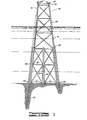
- FIGURE 1 shows a typical offshore platform having jacket legs and pile sleeves thereon having piling driven therethrough; and
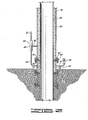
- FIGURE 2 shows in cross-section a leg or pile sleeve and a pile driven therethrough.
- Referring to Figure 1, an
offshore platform 30 having ajacket portion 34,deck portion 33,jacket leg 31 andpile sleeve 32 is resting on the bottom of a body of water is shown having aseal assembly 40 installed on the bottom of eachjacket leg 31 andpile sleeve 32. As shown, when installed, theplatform 30 has the end of eachjacket leg 31 andpile sleeve 32 embedded in the bottom of the body of water.Piles 20 are shown as being driven to depth through ajacket leg 31 andpile sleeve 32. - Referring to Figure 2, an example of a
seal assembly 40 which is used in the improved grouting arrangement of the present invention is shown installed on an annular support member of theplatform 30, such as ajacket leg 31, although it may be apile sleeve 32, having apile 20 driven therethrough. - The improved grouting arrangement of the present invention comprises a seal assembly 40 having either two grout seals or pile wiper assemblies therein, a grout system 60'having a
control valve 64,surface grout line 62 leading to the control valve, afirst line 66 leading from thecontrol valve 64 to theannular space 70 formed between jacket leg and pile driven therethrough and between the grout seal or pile wiper seal assemblies and asecond line 68 leading from the control valve to theannular space 80 between the jacket leg and pile driven therethrough above the upper grout seal or pile wiper assembly, and acheck valve 72 to control the flow of fluid from the annular space formed between a grout seal or pile wiper seal assemblies on ajacket leg 31 and between a jacket leg and pile driven therethrough. - The
seal assembly 40 comprises diaphragm assembly 41, lower pile seal assembly 42, upper pile seal assembly 44, annular housing 45 connecting diaphragm assembly 41 and lower pile seal assembly 42 andhousing 46 which connects the pile seal assemblies 42 and 44. For the purposes of clarity herein, the term pile seal assembly 42 or 44 will refer to either a grout seal or pile wiper seal assembly, such as disclosed in the prior art described hereinbefore, or other such suitable means for enclosure of material. - The diaphragm assembly 41 comprises an elastomeric diaphragm member which has been pierced by
pile 20 being retained on thejacket leg 31 by means of annular flanges secured to housing 45. - The lower pile seal assembly 42 comprises an annular elastomeric pile seal member 42 which sealingly engages the exterior of
pile 20 being retained on thejacket leg 31 by means ofannular flanges 50. - The upper pile seal assembly 44 comprises an annular elastomeric
pile seal member 52 which sealingly engages the exterior ofpile 20 being retained on thejacket leg 31 by means ofannular flanges 54. - The
grouting system 60 on thejacket leg 31 comprises asurface grout line 62 running from the surface of the offshore platform to a location adjacent the lower end of thejacket leg 31 and acontrol valve 64 which communicates withannular space 70 formed betweenjacket leg 31 andpile 20 vialower line 66 and between lower pile seal assembly 42 and upper pile seal assembly 44 andannular space 80 betweenjacket leg 31 andpile 20 above upper pile wiper assembly 44 viaupper line 68. - The
control valve 64 may be of any suitable commercially available valve which is capable of alternately directing fluid flow betweenannular spaces lines - To control the flow of fluid from the
annular space 70 during grouting operations acheck valve 72 communicates vialine 74 withannular space 70. By using acheck valve 72 to control the flow of fluid from theannular space 70 during the initial stage of injecting material intoannular space 70 during the grouting process, the water fromannular space 70 may be removed therefrom without forcing the water past the pile seals 42 and 44, particularly, either the lower pile seal 42 without thereby either disturbing the floor of the body of water in which thejacket leg 31 is resting so that the floor of the body of water may support the lower pile seal 42 and thepierced diaphragm 48 during grouting operations or distributing the seal of the upper pile seal 44 with thepile 20. The check valve 72-may be of any suitable commercially available type. - The improved grouting method of the present invention makes use of a material that can be pumped into
annular space 70 to seal the space, have great enough load bearing strength to support in conjunction withpile seal member 52 an initial grout column inannular space 80, and that will not plug thegrout line 62 after pumping the material therethrough leaving thegrout line 62 suitable for further use. - The improved grouting method of the present invention makes use of such a material and comprises initially pumping or injecting a small fresh water spacer down the
grout line 62 into theannular space 70, subsequently pumping or injecting an alkali silicate material which floculates upon contact with di- or multivalent cation fluids down thegrout line 62 into theannular space 70 while allowing the water therein to flow therefrom throughline 74 and checkvalve 72, then actuating thevalve 64 to prevent flow therefrom vialine 66 while allowing flow therefrom vialine 68 into -annular space 80, next pumping or injecting a fresh water spacer of any desired amount intoannular space 80 to clear any remaining alkali silicate material fromline 62,control valve 64 andline 68 and subsequently pumping or injecting any suitable cement or grouting material down thegrout line 62 intoannular space 80. If desired, a spacer fluid containing di- or multivalent cations, such as a potassium chloride solution, calcium chloride solution, etc., may be pumped into theannular space 70 before the initial fresh water spacer to provide a higher concentration of di- or multivalent cations in theannular spacer 70 with which the alkali silicate material may react. - It should be understood that the amount of fresh water in the initial fresh water spacer should be small in comparison to the volume of
annular space 70 so that theannular space 70 remains substantially filled with sea water or a di- or multivalent cationic fluid with which the alkali silicate material is to react. The function of the first fresh water spacer being to prevent floculation of the alkali silicate material with sea water contained inline 62,control valve 64 andline 66 before the entry of the alkali silicate material intoannular space 70. Similarly, the function of the second fresh water spacer being to prevent floculation of the alkali silicate material remaining inline 62,control valve 64 and any which may have entered intoline 68 while the material is being flushed fromline 62,control valve 64 andline 68 to facilitate the injection of cement or grout intoannular space 80. - If desired, sand, high strength synthetic fibers such a polypropylene fibers, cellulose flakes, ground walnut shells, and other types of lost circulation materials as well as various types of cement may be included'or mixed with the alkali silicate material to increase its strength thereby increasing the amount of grout column the alkali silicate material will support in conjunction with
pile seals annular space 80 during the grout injection portion of the improved grouting method. - If the alkali silicate material in conjunction with the
pile seals 52 will not support a grout column inannular space 80 to completely fill theannular space 80 to the top of thejacket leg portion 34, after the initial grout inannular space 80 has hardened or set, a second injection of grout material intoannular space 80 may be made to fill theannular space 80 from any convenient point on thejacket leg 31, such as from the top 35 thereof. - Also, if desired, the top of the
jacket leg 31 may be sealed-and compressed air or gas may be injected into theannular space 80 between thejacket leg 31 andpile 20 extending therethrough to expell water fromannular space 80, pastupper pile seal 52, and fromannular space 70 vialine 74 andcheck valve 72 so that theannular spaces annular space 70, unless the alkali silicate material is mixed with di- or multivalent cation fluid before the pumping thereof into theannular space 70 which mixing will increase the pumping pressure required to pump the material intoannular space 70, it will be necessary to inject di- or multivalent cation fluid into theannular space 70 to floculate the alkali silicate material pumped thereinto. - If desired, alternately, the alkali silicate material may be pumped into the
annular space 70 and any residual sea water in theannular space 70 and any subsequent sea water leaking past lowerpile seal member 48 and/or grout or cement leaking past upperpile seal member 52 intoannular space 70 may cause sufficient floculation of the alkali silicate material inannular space 70. - The improved grouting method can be used to seal the annulus between either a jacket leg or pile sleeve and a pile driven therethrough utilizing any type
pile seal member pile seal members annulus 80, in many instances, the improved grouting method and arrangement effectively eliminates the need for an inflatable type grout seal at the bottom ofjacket leg 31 in many instances thereby allowing a less expensive grout seal. or pile wiper to be substituted therefore. - In those instances where the
jacket leg 31 is not embedded in or resting on the floor of the body of water in which the platform is installed or the floor of the body of water is too soft or such a soft and muddy bottom to give effective bearing support, the pierced diaphragm and material between the diaphragm andlower pile seal 48 will help support the floculated alkali silicate material inannular space 70. - It should also be evident that the size of the
check valve 72 andline 74 should be selected such that they are easily plugged by the floculated alkali silicate material. - The preferred alkali silicate material which floculates upon contact with di- or multivalent cation fluid or sea water to be used in the improved method of grouting of the current invention is an aqueous sodium silicate solution sold under the trademark FLO-CHEKO Chemical A additive by Halliburton Services, a division of Halliburton Company.
- An alternate material which can be used in the improved method of grouting of the present invention when mixed into an aqueous solution is a powdered silicate having a high ratio of silicon dioxide to alkali metal oxide sold under the trademark FLO-CHEK® P additive by Halliburton Services, a division of Halliburton Company.
- When using the preferred material, FLO-CHEK® Chemical A additive, in the improved method of grouting and arrangement of the present invention, any desired amount of material may be pumped or injected into the annulus to be grouted depending upon the strength required to support the desired column of cement or grout to be injected into the leg to form a plug or fill the annulus. Therefore, the length of the housing between the
pile seals annular space 70 to be filled should be preferably at least four (4) feet of axial length of theannular space 70, to be sufficient to support an adequate column of cement or grout to be injected into theannular space 80 abovepile seal 52. - Although FZO-CHEK® Chemical A additive or FLO-CHEK® P additive are the preferred materials to be used in the improved grouting method of the present invention, any alkali silicate having a molar ratio of silicon dioxide (Si02) to alkali metal oxide (sodium, potassium, ammonium or lithium) between approximately 1.6 or less to 4.0 may be used.
- Also, although it is preferred to use an initial spacer of fresh water before the injection of the alkali silicate material and spacer of fresh water after the injection of the alkali silicate material, the fresh water spacers may be eliminated, if the alkali silicate material can be prevented from floculating during pumping through the
grout line 62,grout control valve 64 andlines annular space 70. - It will be obvious to those skilled in the art that such an improved grouting method and grouting arrangement may be modified to be used on a wide variety of marine structures in various locations thereon where it is desired to seal an annular space and grout the area located thereabove, such modifications being within the scope of the present invention.
Claims (10)
Priority Applications (1)
| Application Number | Priority Date | Filing Date | Title |
|---|---|---|---|
| DE8585303976T DE3568811D1 (en) | 1985-06-05 | 1985-06-05 | Grouting annuli in offshore platforms |
Applications Claiming Priority (1)
| Application Number | Priority Date | Filing Date | Title |
|---|---|---|---|
| US06/591,701 US4552486A (en) | 1984-03-21 | 1984-03-21 | Grouting method - chemical method |
Publications (2)
| Publication Number | Publication Date |
|---|---|
| EP0204041A1 true EP0204041A1 (en) | 1986-12-10 |
| EP0204041B1 EP0204041B1 (en) | 1989-03-15 |
Family
ID=24367535
Family Applications (1)
| Application Number | Title | Priority Date | Filing Date |
|---|---|---|---|
| EP85303976A Expired EP0204041B1 (en) | 1984-03-21 | 1985-06-05 | Grouting annuli in offshore platforms |
Country Status (4)
| Country | Link |
|---|---|
| US (1) | US4552486A (en) |
| EP (1) | EP0204041B1 (en) |
| AU (1) | AU578701B2 (en) |
| CA (1) | CA1241847A (en) |
Cited By (3)
| Publication number | Priority date | Publication date | Assignee | Title |
|---|---|---|---|---|
| WO1991001411A1 (en) * | 1989-07-14 | 1991-02-07 | Offshore Innovation Limited A/S | Jackable oil rigs and corner columns for producing legs in an oil rig |
| EP2672016A1 (en) | 2012-06-04 | 2013-12-11 | RWE Innogy GmbH | Grout seal and method to grout an annular space between two foundation members of an offshore structure |
| EP2851471A3 (en) * | 2013-09-24 | 2015-04-08 | RWE Innogy GmbH | Building structure, in particular underwater structure of an offshore structure and method for the construction of an offshore building |
Families Citing this family (13)
| Publication number | Priority date | Publication date | Assignee | Title |
|---|---|---|---|---|
| US4902170A (en) * | 1988-11-16 | 1990-02-20 | Halliburton Company | Grouting method - chemical method |
| US5226751A (en) * | 1992-02-04 | 1993-07-13 | Doleshal Donald L | Controlling the environment around a submerged pile or other structures by encapsulation, and treating and repairing the encapsulation area |
| AU704415B2 (en) * | 1995-03-03 | 1999-04-22 | American Oilfield Divers, Inc. | Offshore well saving apparatus and method |
| US6357968B1 (en) * | 2000-01-12 | 2002-03-19 | Sandia Corporation | Method and apparatus for constructing an underground barrier wall structure |
| US6902002B1 (en) * | 2004-03-17 | 2005-06-07 | Halliburton Energy Services, Inc. | Cement compositions comprising improved lost circulation materials and methods of use in subterranean formations |
| GB2433540A (en) * | 2005-12-22 | 2007-06-27 | Martin Hardy | Brush seal for grouting annuli |
| NL2003073C2 (en) * | 2009-06-23 | 2010-12-27 | Ihc Holland Ie Bv | DEVICE AND METHOD FOR REDUCING SOUND. |
| US8596919B2 (en) * | 2010-11-23 | 2013-12-03 | Technip France | Anti-scour disk and method |
| EP2623674A1 (en) * | 2012-02-03 | 2013-08-07 | Nordic Yards Holding GmbH | Substructure for an offshore platform and method for installing same |
| NO2765895T3 (en) * | 2014-02-06 | 2018-08-04 | ||
| NL2014069B1 (en) * | 2014-12-29 | 2016-10-12 | Ihc Holland Ie Bv | Noise mitigation system |
| DE102017118375A1 (en) * | 2017-08-11 | 2019-02-14 | Innogy Se | Offshore construction |
| CN111663555B (en) * | 2020-06-24 | 2021-10-22 | 浙江大学 | Jacket pile shoe sealing system based on expanded high polymer and sealing method thereof |
Citations (3)
| Publication number | Priority date | Publication date | Assignee | Title |
|---|---|---|---|---|
| FR2320392A1 (en) * | 1975-08-04 | 1977-03-04 | Lynes Inc | METHOD AND DEVICE FOR CEMENTING UNDERWATER WORKS |
| US4181454A (en) * | 1978-07-20 | 1980-01-01 | Halliburton Company | Pile wiper seal |
| EP0104795A2 (en) * | 1982-09-28 | 1984-04-04 | Halliburton Company | Method of grouting annulus |
Family Cites Families (41)
| Publication number | Priority date | Publication date | Assignee | Title |
|---|---|---|---|---|
| US28232A (en) * | 1860-05-08 | Improvement in potato-diggers | ||
| US2653451A (en) * | 1948-07-02 | 1953-09-29 | Brown And Root Inc | Pedestal |
| US2927435A (en) * | 1955-09-23 | 1960-03-08 | Raymond Int Inc | Offshore platforms |
| US2953904A (en) * | 1958-04-03 | 1960-09-27 | Lowell B Christenson | Submersible barge assembly |
| US3209544A (en) * | 1963-05-27 | 1965-10-05 | California Research Corp | Marine structure |
| US3347053A (en) * | 1965-04-28 | 1967-10-17 | Mobil Oil Corp | Partially salvageable jacket-pile connection |
| US3315473A (en) * | 1965-08-27 | 1967-04-25 | Brown & Root | Offshore platform |
| US3468132A (en) * | 1967-03-01 | 1969-09-23 | Oil States Rubber Co | Platform leg packer |
| US3457728A (en) * | 1968-03-26 | 1969-07-29 | Texaco Inc | Replaceable pile sleeve insert |
| US3533241A (en) * | 1968-07-12 | 1970-10-13 | Oil States Rubber Co | Rupturable seal assembly for piling guides |
| US3564856A (en) * | 1969-04-11 | 1971-02-23 | Mobil Oil Corp | Process and apparatus for cementing offshore support members |
| US3601999A (en) * | 1969-09-18 | 1971-08-31 | Horace W Olsen | Methods of grouting offshore structures |
| US3592012A (en) * | 1969-09-23 | 1971-07-13 | Texaco Inc | Laterally reinforced offshore platform |
| US3570259A (en) * | 1969-11-13 | 1971-03-16 | Oil States Rubber Co | Annulus seal and pile wiper |
| US3702537A (en) * | 1970-10-14 | 1972-11-14 | Oil States Rubber Co | Grouting seal for piling |
| FR2184147A5 (en) * | 1972-05-08 | 1973-12-21 | Gem | |
| US3878687A (en) * | 1973-07-19 | 1975-04-22 | Western Co Of North America | Grouting of offshore structures |
| US3838575A (en) * | 1973-09-26 | 1974-10-01 | R Clark | Method of grouting offshore structure |
| US3967456A (en) * | 1973-11-19 | 1976-07-06 | Deep Sea Grouting Packers, Inc. | Sealing devices |
| US3919850A (en) * | 1974-05-01 | 1975-11-18 | Lynes Inc | Structure and method of positioning for use in water covered areas |
| US4041718A (en) * | 1974-11-14 | 1977-08-16 | Deep Sea Grouting Packers, Inc. | Sealing devices |
| US4009581A (en) * | 1975-05-19 | 1977-03-01 | Oil States Rubber Company | Grout line protected pressure lines for setting sleeve packers |
| US4052861A (en) * | 1975-08-04 | 1977-10-11 | Lynes, Inc. | Inflatable securing arrangement |
| US4063427A (en) * | 1975-08-04 | 1977-12-20 | Lynes, Inc. | Seal arrangement and flow control means therefor |
| US4014174A (en) * | 1975-10-28 | 1977-03-29 | N L Industries, Inc. | Method of simultaneously strengthening the surface of a borehole and bonding cement thereto and method of forming cementitious pilings |
| US4077224A (en) * | 1976-05-13 | 1978-03-07 | Lynes, Inc. | Method and apparatus for grouting an offshore structure |
| US4024723A (en) * | 1976-06-24 | 1977-05-24 | Regal Tool & Rubber Co. Inc. | Platform leg diaphragm |
| US4047391A (en) * | 1976-06-24 | 1977-09-13 | Regal Tool & Rubber Co., Inc. | Grout seal |
| US4070869A (en) * | 1977-02-14 | 1978-01-31 | Kenneth Anthony Williams | Method of grouting offshore structure |
| US4184790A (en) * | 1977-03-01 | 1980-01-22 | C. Nelson Shield, Jr., Trustee | Submerged pile grouting |
| US4120166A (en) * | 1977-03-25 | 1978-10-17 | Exxon Production Research Company | Cement monitoring method |
| US4372704A (en) * | 1977-07-22 | 1983-02-08 | Halliburton Company | Method and apparatus for grouting of offshore platform pilings |
| JPS54128102A (en) * | 1978-03-28 | 1979-10-04 | Kawasaki Steel Co | Method of construction of portion material connection fixing of underwater structure |
| US4140426A (en) * | 1977-10-21 | 1979-02-20 | Halliburton Company | System for inflating packers and placing grout through one line |
| US4171923A (en) * | 1978-05-09 | 1979-10-23 | Oil States Rubber Company | Offshore structure gravity grouting method |
| US4412759A (en) * | 1978-05-11 | 1983-11-01 | Oil States Industries, Inc. | Reach rod grouting system |
| US4275974A (en) * | 1979-02-15 | 1981-06-30 | Halliburton Company | Inflation and grout system |
| US4279546A (en) * | 1979-05-29 | 1981-07-21 | Oil States Rubber Company | Grout seal premature inflation protective system |
| US4310265A (en) * | 1980-02-29 | 1982-01-12 | Halliburton Company | Pile wiper seal |
| US4311414A (en) * | 1980-02-29 | 1982-01-19 | Halliburton Company | Pile wiper seal |
| US4422805A (en) * | 1980-12-31 | 1983-12-27 | Hughes Tool Company | Method of grouting offshore structures |
-
1984
- 1984-03-21 US US06/591,701 patent/US4552486A/en not_active Expired - Lifetime
-
1985
- 1985-05-29 AU AU43108/85A patent/AU578701B2/en not_active Ceased
- 1985-06-05 EP EP85303976A patent/EP0204041B1/en not_active Expired
- 1985-06-05 CA CA000483220A patent/CA1241847A/en not_active Expired
Patent Citations (3)
| Publication number | Priority date | Publication date | Assignee | Title |
|---|---|---|---|---|
| FR2320392A1 (en) * | 1975-08-04 | 1977-03-04 | Lynes Inc | METHOD AND DEVICE FOR CEMENTING UNDERWATER WORKS |
| US4181454A (en) * | 1978-07-20 | 1980-01-01 | Halliburton Company | Pile wiper seal |
| EP0104795A2 (en) * | 1982-09-28 | 1984-04-04 | Halliburton Company | Method of grouting annulus |
Cited By (5)
| Publication number | Priority date | Publication date | Assignee | Title |
|---|---|---|---|---|
| WO1991001411A1 (en) * | 1989-07-14 | 1991-02-07 | Offshore Innovation Limited A/S | Jackable oil rigs and corner columns for producing legs in an oil rig |
| AU639006B2 (en) * | 1989-07-14 | 1993-07-15 | Offshore Innovation Limited A/S | Jackable oil rigs and corner columns for producing legs in an oil rig |
| US5288174A (en) * | 1989-07-14 | 1994-02-22 | Offshore Innovation Limited A/S | Jackable oil rigs and corner columns for producing legs in an oil rig |
| EP2672016A1 (en) | 2012-06-04 | 2013-12-11 | RWE Innogy GmbH | Grout seal and method to grout an annular space between two foundation members of an offshore structure |
| EP2851471A3 (en) * | 2013-09-24 | 2015-04-08 | RWE Innogy GmbH | Building structure, in particular underwater structure of an offshore structure and method for the construction of an offshore building |
Also Published As
| Publication number | Publication date |
|---|---|
| CA1241847A (en) | 1988-09-13 |
| US4552486A (en) | 1985-11-12 |
| EP0204041B1 (en) | 1989-03-15 |
| AU578701B2 (en) | 1988-11-03 |
| AU4310885A (en) | 1986-12-04 |
Similar Documents
| Publication | Publication Date | Title |
|---|---|---|
| US4493592A (en) | Grouting method | |
| EP0204041B1 (en) | Grouting annuli in offshore platforms | |
| EP0369591B1 (en) | Grouting well platform legs | |
| US4422805A (en) | Method of grouting offshore structures | |
| US4184790A (en) | Submerged pile grouting | |
| US3878687A (en) | Grouting of offshore structures | |
| US3564856A (en) | Process and apparatus for cementing offshore support members | |
| US2025948A (en) | Method of grouting by chemical means | |
| US3832857A (en) | Pressure grouting | |
| US4070869A (en) | Method of grouting offshore structure | |
| CS205052B2 (en) | Method of improving strength and impermeability of crumbled material and/or solid products | |
| GB2433540A (en) | Brush seal for grouting annuli | |
| US3464494A (en) | Method of plugging earth formations with fluoride catalyzed silicic acid chemical grout | |
| AU615207B2 (en) | Grouting arrangement for an offshore platform | |
| GB2325479A (en) | Wellbore plug | |
| RU2209928C1 (en) | Method of isolation of absorption zones in well | |
| RU2002109854A (en) | The method of sealing pipe and annular space | |
| RU2345212C1 (en) | Casting method of cementing | |
| CA1158447A (en) | Method of grouting offshore structures | |
| SU1532648A1 (en) | Method, liquid consolidating material, and method of its preparation for consolidating shore soil body | |
| Pro | Water control using polyurethane resins | |
| RU2016188C1 (en) | Method for oil and gas well casing cementing | |
| NO852206L (en) | METHOD INITIATION PROCEDURE. | |
| CA1135064A (en) | Submerged pile grouting | |
| JPS5825129B2 (en) | Composite grouting method |
Legal Events
| Date | Code | Title | Description |
|---|---|---|---|
| PUAI | Public reference made under article 153(3) epc to a published international application that has entered the european phase |
Free format text: ORIGINAL CODE: 0009012 |
|
| AK | Designated contracting states |
Kind code of ref document: A1 Designated state(s): DE GB IT NL |
|
| 17P | Request for examination filed |
Effective date: 19861211 |
|
| 17Q | First examination report despatched |
Effective date: 19880201 |
|
| ITF | It: translation for a ep patent filed |
Owner name: BARZANO' E ZANARDO MILANO S.P.A. |
|
| GRAA | (expected) grant |
Free format text: ORIGINAL CODE: 0009210 |
|
| AK | Designated contracting states |
Kind code of ref document: B1 Designated state(s): DE GB IT NL |
|
| REF | Corresponds to: |
Ref document number: 3568811 Country of ref document: DE Date of ref document: 19890420 |
|
| PLBE | No opposition filed within time limit |
Free format text: ORIGINAL CODE: 0009261 |
|
| STAA | Information on the status of an ep patent application or granted ep patent |
Free format text: STATUS: NO OPPOSITION FILED WITHIN TIME LIMIT |
|
| 26N | No opposition filed | ||
| ITTA | It: last paid annual fee | ||
| PGFP | Annual fee paid to national office [announced via postgrant information from national office to epo] |
Ref country code: DE Payment date: 19950607 Year of fee payment: 11 |
|
| PGFP | Annual fee paid to national office [announced via postgrant information from national office to epo] |
Ref country code: NL Payment date: 19950628 Year of fee payment: 11 |
|
| NLS | Nl: assignments of ep-patents |
Owner name: CONTINENTAL EMSCO COMPANY |
|
| PG25 | Lapsed in a contracting state [announced via postgrant information from national office to epo] |
Ref country code: NL Effective date: 19970101 |
|
| PG25 | Lapsed in a contracting state [announced via postgrant information from national office to epo] |
Ref country code: DE Effective date: 19970301 |
|
| NLV4 | Nl: lapsed or anulled due to non-payment of the annual fee |
Effective date: 19970101 |
|
| PGFP | Annual fee paid to national office [announced via postgrant information from national office to epo] |
Ref country code: GB Payment date: 20000531 Year of fee payment: 16 |
|
| PG25 | Lapsed in a contracting state [announced via postgrant information from national office to epo] |
Ref country code: GB Free format text: LAPSE BECAUSE OF NON-PAYMENT OF DUE FEES Effective date: 20010605 |
|
| GBPC | Gb: european patent ceased through non-payment of renewal fee |
Effective date: 20010605 |